Spin Selection Rule-Based Sub-Millisecond Hyperpolarization of Nuclear Spins in Silicon
Abstract
In this work, we devise a fast and effective nuclear spin hyperpolarization scheme, which is in principle magnetic field and temperature independent. We use this scheme to experimentally demonstrate polarizations of up to 66 for phosphorus donor nuclear spins in bulk silicon, which are created within less than 100 s in a magnetic field of 0.35 T at a temperature of 5 K. The polarization scheme is based on a spin-dependent recombination process via weakly-coupled spin pairs, for which the recombination time constant strongly depends on the relative orientation of the two spins. We further use this scheme to measure the nuclear spin relaxation time and find a value of 100 ms under illumination, in good agreement with the value calculated for nuclear spin flips induced by repeated ionization and deionization processes.
Nuclear spins in semiconductors have been intensively studied in the last decades as sensitive probes of the electronic structure of defects and, due to their exceptionally long decoherence times Steger et al. (2012), also as qubits for quantum information processing Pla et al. (2013) or as a potential resource for a quantum memory Morton et al. (2008). However, their small magnetic moments and the resulting small polarization often impede their direct detection by nuclear magnetic resonance techniques, so that one has to resort to indirect detection schemes Feher (1956); Dobers et al. (1988); Smet et al. (2004); Stich et al. (1996). An alternative strategy has focused on increasing the nuclear spin polarization above its thermal equilibrium value. Such hyperpolarization techniques have found widespread applications in magnetic resonance imaging Möller et al. (2002), where in particular hyperpolarized silicon nanoparticles have been suggested as versatile agents for in-vivo imaging Schröder et al. (2006); Cassidy et al. (2013). Further, in the context of spin-based quantum information processing, hyperpolarization schemes might be useful to initialize spin-based qubits DiVincenzo (2000); Simmons et al. (2011) or to improve the coherence times of electron spins coupled to a nuclear spin bath Koppens et al. (2005).
Different hyperpolarization schemes of nuclear spins in silicon have been discussed, which mostly rely on the transfer of angular momentum from a polarized electron spin bath to the nuclear spins. While in direct semiconductors, circularly polarized light can be used to create spin-polarized electrons or holes Puttisong et al. (2013), this approach is not applicable to indirect semiconductors such as Si, where in most cases high magnetic fields and low temperatures are required Vlasenko et al. (1986); Aptekar et al. (2009); McCamey et al. (2009); Simmons et al. (2011); Lo et al. (2013). Recently, an efficient hyperpolarization procedure has been demonstrated for 31P in silicon based on the hyperfine selective optical excitation of donor-bound excitons, which however requires the use of ultrapure isotopically enriched 28Si Yang et al. (2009). In addition, all of these hyperpolarization schemes in silicon require time constants of at least 100 ms.
Here, we devise a fast and effective nuclear spin hyperpolarization scheme, based on a spin-dependent recombination process via weakly-coupled spin pairs Kaplan et al. (1978) as detailed below. We use this technique to experimentally demonstrate a large polarization of phosphorus donor nuclear spins in bulk silicon with natural isotope composition, which is created within less than 100 s in a magnetic field of 0.35 T at a temperature of 5 K.
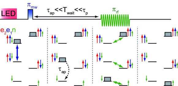
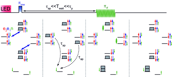
Considering a weakly coupled spin pair consisting of two electron spins e1 and e2 (red and blue arrows in Fig. 1, resp.) with an additional nuclear spin n (green arrow) coupled by a hyperfine interaction to e1, the difference in the recombination time constants and of parallel and antiparallel electron spin pairs, resp., leads to large steady-state population differences under above-bandgap illumination Hoehne et al. (2013). States with both electron spins oriented in parallel are occupied (gray boxes) while antiparallel states are basically empty as shown exemplarily for e2 spins up in Fig. 1. This population difference can be transferred to the nuclear spins by the combination of a resonant microwave (mw) and radio-frequency (rf) pulse similar to a standard Davies ENDOR experiment Davies (1974), as illustrated in detail in the first three panels in Fig. 1. However, since the recombination of antiparallel spin pairs takes place on timescales of the order of microseconds Hoehne et al. (2013), which is significantly shorter than the typical rf pulse length, this population transfer is rather inefficient Hoehne et al. (2011). Therefore, by introducing a waiting period between the mw and rf pulse (Fig. 1), which is chosen much longer than the recombination time of antiparallel spin pairs and much shorter than the recombination time of parallel spin pairs, all antiparallel spin pairs created by the mw pulse have recombined before the rf pulse. In addition, the illumination can be switched off during the pulse sequence to prevent new e1-e2 spin pairs to be formed by electron and hole capture processes Dreher et al. (2012). After these modifications, the population differences are stable on the much longer time scale , allowing for an efficient manipulation of the nuclear spins.
This modified hyperpolarization scheme enables an almost complete transfer of the initial population difference between the antiparallel and parallel states to the nuclear spins by a single application of the pulse sequence shown in Fig. 1. Since the initial population difference is determined by the parallel and antiparallel recombination rates and, therefore, is independent of the magnetic field, an almost complete polarization of the nuclear spins is possible even at low magnetic fields in contrast to most conventional hyperpolarization schemes, which transfer at most the thermal equilibrium electron spin polarization to the nuclear spins Rosay et al. (2003).
For 31P nuclear spins in silicon, at least two spin pairs can be employed for the presented hyperpolarization scheme, namely the 31P-Pb0 spin pair at the Si/SiO2 interface Hoehne et al. (2010) and the 31P-SL1 spin pair in -irradiated bulk silicon Stich et al. (1995). In the following, we will focus on the latter to experimentally demonstrate the hyperpolarization using a crystalline bulk phosphorus-doped Czochralski-grown silicon sample which has been exposed to -irradiation from a 60Co source. This creates oxygen-vacancy complexes which, under above-bandgap illumination, are excited into a metastable triplet state (SL1) Brower (1971) with a lifetime of the order of hundreds of microseconds at 5 K Akhtar et al. (2012). SL1 centers and 31P donors in spatial proximity form weakly coupled spin pairs giving rise to an efficient spin-dependent recombination process, which can be observed using electrically detected magnetic resonance (EDMR) as a resonant change in the photoconductivity Stich et al. (1995).
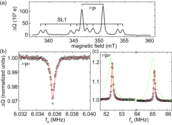
To verify the presence of 31P-SL1 spin pairs in the sample, we first record a pulsed EDMR spectrum Boehme and Lips (2003); Stegner et al. (2006). To this end, we place the sample at 5 K in a dielectric resonator for pulsed ENDOR, illuminate it with above-bandgap light from an LED (wavelength 635 nm) and irradiate it with mw pulses of fixed length (70 ns) and frequency (=9.739 GHz). The illumination intensity is calibrated by a photodetector inside the resonator. The current transients after the pulse sequence are amplified by a current amplifier, recorded with a fast data acquisition card and are box-car integrated, yielding a charge which is proportional to the number of antiparallel spin pairs at the end of the mw pulse sequence Boehme and Lips (2003). Further details of the method are given in Ref. Dreher et al. (2012). The corresponding spectrum [Fig. 2(a)] reveals the two hyperfine-split 31P peaks and eight peaks at magnetic field values in perfect agreement with the expected peak positions of the SL1 center Brower (1971). The presence of an 31P-SL1 spin pair recombination process already indicated by the observation of both electron spin transitions in Fig. 2(a) can be directly confirmed using electrically detected electron electron double resonance Franke et al. (2013).
To further assess the suitability of the 31P-SL1 spin pair for hyperpolarization, we determine the 31P-SL1 recombination time constants using a combination of pulsed optical excitation and pulsed spin manipulation Dreher et al. (2012). We find values of 4 s and 300 s, confirming that antiparallel 31P-SL1 spin pairs recombine much faster than parallel spin pairs as required for the hyperpolarization scheme. We further characterize the spin transitions of the 31P nuclear spins both in the neutral and ionized state of the donor using pulsed electrically detected electron nuclear double resonance Hoehne et al. (2011); Dreher et al. (2012). The spectra [Fig. 2(b) and 2(c)] reveal a quenching of the echo signal at a frequency of =6.0358(1) MHz with an rf pulse excitation bandwidth-limited FWHM of 230 Hz, which corresponds to a nuclear -factor of =-2.2606(3), in good agreement with the value of =-2.2601(3) observed at the Si/SiO2 interface Dreher et al. (2012). Enhancements of the echo signal are found at frequencies of 52.38(1) MHz and 65.15(1) MHz (FWHM=100 kHz) corresponding to nuclear spin transitions of the neutral 31P donor. The corresponding hyperfine interaction of =117.54(2) MHz is in good agreement with the value of =117.523936(1) MHz for 31P donors in bulk 28Si Steger et al. (2011). In contrast, for the 31P donors near the Si/SiO2 interface [green dashed lines in Fig. 2(c)], the nuclear spin transition frequencies correspond to a significantly smaller hyperfine constant of MHz Dreher et al. (2012), which we attribute to strain at the surface Wilson and Feher (1961); Huebl et al. (2006) caused by the evaporated metal contacts and their different thermal expansion coefficient compared to Si. Inhomogeneous strain might also explain the four times larger linewidth of these transitions.
Based on the hyperpolarization scheme presented above, polarization of the 31P nuclear spins is created using the pulse sequence shown in Fig. 3(a) (e1=31P, e2=SL1) with an rf pulse on the nuclear spin transition of the 31P+ at 6.036 MHz [cf. full green arrow in Fig. 1(a)] or alternatively on one of the two 31P0 nuclear spin transitions at 52.38 MHz or 65.15 MHz [cf. dotted green arrows in Fig. 1(a)]. For the ideal case shown in Fig. 1(a), a polarization of 100% for the 6.036 MHz nuclear spin transition is expected after one application of the pulse sequence. In contrast, only 50% can be achieved for the 52.38 MHz and 65.15 MHz transitions if only one of the two hyperfine-split 31P0 nuclear spin transitions is excited (Appendix A). Application of two subsequent rf pulses with 52.38 MHz and 65.15 MHz increases the maximum achievable polarization from 50% to 100% also for these transitions.
The resulting nuclear spin polarization is determined after repopulating the donors by optical excitation for 500 s to generate carriers in the conduction and valence bands and subsequent capture processes, assuming that the nuclear spin polarization is mostly unaffected by the repopulation process, which we will confirm below. Since only the nuclear spins of donors forming 31P-SL1 spin pairs are polarized, we use an electrically detected spin echo technique Huebl et al. (2008); Hoehne et al. (2012) instead of conventional electron spin resonance to only measure the polarization of these nuclear spins. The amplitude of the spin echo is compared with the spin echo amplitude after application of the same pulse sequence without or with off-resonant rf pulses. The measured nuclear spin polarization is given by . To determine the value of obtained after a single repetition of the pulse sequence, we illuminate the sample for several hundreds of ms before applying the pulse sequence. This is much longer than the 31P nuclear spin relaxation time under illumination (100 ms) as determined below, leading to an effective randomization or reset of the nuclear spin system.
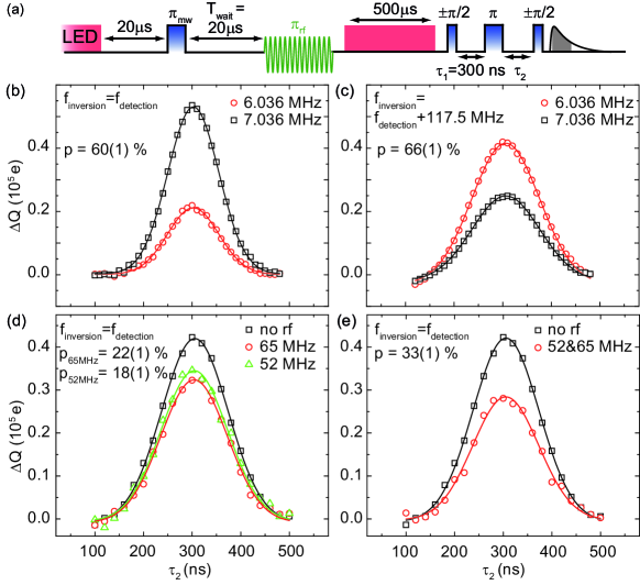
Using the 6.036 MHz nuclear spin transition, we experimentally achieve a hyperpolarization of =60 for a single pulse sequence. Figure 3(b) shows the corresponding spin echoes with a resonant rf pulse (black squares) and an off-resonant rf pulse (red circles) for =300 ns as a function of , with waiting times and after the first and second detection echo mw pulse, resp.. The values of and are determined by Gaussian fits (solid lines). The echo amplitude for the case of hyperpolarized nuclei is reduced compared with the reference as expected when the detection echo is measured on the same 31P electron spin hyperfine-split transition as the mw inversion pulse (cf. Fig. 1). Similarly, an increase of the echo amplitude is expected for the case that the detection echo and the inversion pulse are applied to different hyperfine transitions. To demonstrate this, we use a second mw source for the detection echo pulses detuned by the 31P hyperfine splitting of 117.5 MHz from the source for the inversion pulse. As shown in Fig. 3 (c), we indeed observe an increase of the echo amplitude for a resonant rf pulse corresponding to a hyperpolarization of 66 , also demonstrating that the observed polarization is not a spurious effect due to, e.g., heating by the strong rf pulses.
We can also use the 52.38 MHz and 65.15 MHz nuclear spin transition of the neutral donor for hyperpolarization, although we expect a smaller polarization value due to the lower fidelity of the rf pulse on the inhomogeneously broadened 31P0 nuclear spin transition in Si with natural isotope composition. This is indeed observed as shown in Fig. 3(d), where polarization values of 18 and 22 are achieved for the 52 MHz and 65 MHz nuclear spin transitions, resp.. The polarization can be increased to 33 by applying two subsequent rf pulses on both nuclear spin transitions as shown in Fig. 3(e).
The nuclear spin hyperpolarization values of 60 and 66 exceed the thermal equilibrium polarization of the 31P nuclear spins at 0.35 T and 5 K of 3 by a factor of and even exceed the thermal equilibrium electron spin polarization of 5% under these conditions by a factor of 12. This is achieved after a single repetition of the pulse sequence taking less than 100 s, demonstrating that we have realized a fast and efficient nuclear spin hyperpolarization scheme.
The fidelity of the polarization scheme depends on several aspects. First, the excitation bandwidth of the mw and rf polarization pulses has to be much larger than the linewidth of the electron and nuclear spin transitions to allow for high-fidelity pulses. For both, the 31P electron and the 31P+ nuclear spin, the excitation bandwidths of 50 MHz and 20 kHz are much larger than the linewidths of 8 MHz Lu et al. (2011) and 230 Hz, resp.. From these values, we estimate a pulse fidelity of >90% and 100% for the mw and rf pulse, resp.. Further, the difference between and has to be sufficiently large so that the condition can be fullfilled, where we also take the length of the rf pulse into account. For the 31P-SL1 spin pair, we estimate that in addition to all antiparallel spin pairs, also a fraction of 1-0.2 of parallel spin pairs recombines until the end of the rf pulse. Although only a rough estimate, this partly explains the observed maximum nuclear spin polarization of 66%. A more detailed analysis should include a detailed model of the spin pair dynamics Hoehne et al. (2013) and also take into account the variation of recombination time constants over the spin pair ensemble.
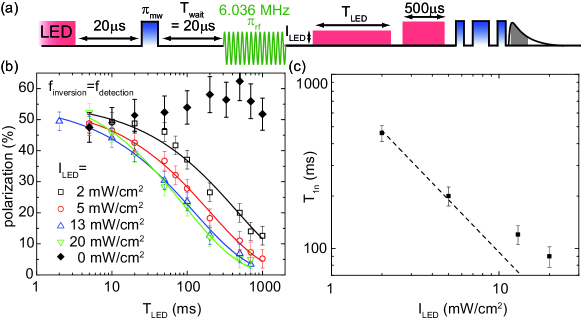
Having established a large single shot hyperpolarization, we proceed by measuring the nuclear spin relaxation time for different illumination intensities. To this end, we use the hyperpolarization and detection pulse sequence discussed above and apply an additional light pulse of variable length and intensity between the rf pulse and the detection [see Fig. 4(a)]. Again, a more than 500 ms long illumination pulse is applied before each repetition of the pulse sequence to ensure that the nuclear spins are randomized. Figure 4(b) shows the decay of the nuclear spin polarization as a function of for different (open symbols) measured for the 31P+ nuclear spin transition as in Fig. 3(b). We observe a nuclear spin relaxation time of 100 ms for the highest illumination intensity as determined by a single exponential fit. For low , decreases approx. as indicated by the dashed line in Fig. 4(b). Without illumination, a small increase rather than a decrease of the polarization is observed for time intervals as long as 1 s [full diamonds in Fig. 4(b)]. The latter observation is in line with the very long 31P nuclear spin relaxation time of 10 hours that has been found in bulk Si:P samples at 0.32 T and 1.25 K without above-bandgap illumination Feher and Gere (1959).
is shortened by optical excitation of carriers into the conduction and valence bands. Possible relaxation mechanisms are, e.g., the scattering of conduction band electrons with the 31P nuclei, leading to spin flip-flop processes, which however predicts relaxation times of several hours at 0.3 T Overhauser (1953); Feher and Gere (1959); McCamey et al. (2009). Nuclear spin flips can also be induced by repeated ionization and deionization of the 31P donor because of the mixing of the high-field eigenstates by the hyperfine interaction Pla et al. (2013).
The probability of a nuclear spin flip for each ionization/deionization process is given by Pla et al. (2013), where denotes the mixing angle as defined, e.g., in Ref. Steger et al. (2011), with the 31P hyperfine coupling =117.5 MHz and the 31P electron spin Larmor frequency =9.798 GHz at =350.3 mT. A detailed analysis of the time evolution of the spin system (Appendix B) shows that for high with =4 s results in =110 ms, in very good agreement with the experimentally observed relaxation time. For lower , the formation rate of new spin pairs by electron and hole capture processes decreases Hoehne et al. (2013), resulting in an increase of the average time the spin pair spends in the ionized state. This reduces the ionization rate and therefore the nuclear spin flip rate, explaining the observed increase of with decreasing [cf. Fig. 4(c)].
To summarize, we have demonstrated a fast and effective nuclear spin polarization scheme for 31P nuclear spins in natural Si at 5 K achieving a polarization of 66% within less than 100 s. The polarization scheme does not rely on thermal equilibrium spin polarizations and therefore works at easily accessible magnetic fields and temperatures. We further note, that no electrical contacts are needed to create the polarization, they were used solely for the measurement of the polarization. The density of polarized nuclear spins in the studied sample is at most 1012 cm-3, limited by the concentration of SL1 centers, and therefore orders of magnitude too small for a possible application in magnetic resonance imaging. However, systems with a much larger density of spin pairs can be envisaged like, e.g., P-doped silicon nanoparticles. Here, the nanoparticle diameter, the doping concentration and the density of dangling bond defects can be adjusted such that each nanoparticle contains one P donor and one defect with high probability Almeida et al. (2012); Niesar et al. (2012), so that spin pair densities of more than 1017 cm-3 could be achieved, sufficient for nuclear magnetic resonance imaging. For such 31P-Pb0 spin pairs, we have obtained a nuclear spin polarization of 30% at the Si:P/SiO2 interface, indicating that the described method is also applicable to them.
The work was funded by DFG (Grant No. SFB 631, C3 and Grant No. SPP 1601, Br 1585/8), the JST-DFG Strategic Cooperative Program on Nanoelectronics, the Core-to-Core Program by JSPS, FIRST, and a Grant-in-Aid for Scientific Research and Project for Developing Innovation Systems by MEXT.
Appendix A Polarization Scheme of 31P0 Nuclear Spins
In Fig. 1, we sketched the nuclear spin hyperpolarization scheme showing only four of the eight states of the spin system. We argued, that for an rf pulse on the 31P+ nuclear spin transition a maximum polarization of 100% is expected, while for rf pulses on the two 31P0 nuclear spin transitions this value is reduced to 50%. The reason for the latter can most easily be seen by visualizing the spin state populations for all eight states of the spin system as shown in Fig. 5. There, we exemplarily sketch the hyperpolarization sequence for an rf pulse resonant with one of the 31P0 nuclear spin transitions (green arrow) resulting in a population of 1/4 for the nuclear spin up states and 3/4 for the nuclear spin down states, which corresponds to a polarization of 50%. In contrast, an rf pulse on the 31P+ transition or two rf pulses on both 31P0 nuclear spin transitions completely polarize the nuclear spins.
Appendix B Nuclear Spin Relaxation under Illumination
In this section, we discuss the relaxation time of the 31P nuclear spins caused by the ionization/deionization process under above-bandgap illumination. The hyperfine interaction leads to a mixing of states with different nuclear spin orientations. Upon ionization, the mixed state is projected on the 31P+ nuclear spin up or spin down eigenstate with a certain probability of a nuclear spin flip, which we calculate below. The nuclear spin relaxation rate is then calculated by multiplying with the effective recombination rate.
For the 31P electron spin e1 coupled to the 31P nuclear spin n by a hyperfine interaction , the Hamiltonian is given by
| (1) |
with the 31P electron spin Larmor frequency , and the electron spin and nuclear spin operators and , respectively. For , the eigenstates of are given by ,, , and , where the first arrow denotes the electron spin state and the second arrow the nuclear spin state. The hyperfine coupling leads to a mixing of these high-field states and the eigenstates of become
| (2) |
where we have also introduced the electron spin e2 denoted by the very first arrow as the recombination partner of the 31P electron spin shown exemplarily only for spin up. The mixing angle is defined as
| (3) |
For the experimental conditions in this work (9.798 GHz, =117.5 MHz), we obtain =6, so that the nuclear spin flip probability is .
We further introduce an operator describing the spin-dependent transition into the ionized 31P+ state denoted by () for the 31P nuclear spin up (down). We assume that conserves the nuclear spin state. Since the recombination time constants of the unmixed states and are and , resp., the matrix elements of are given by
| (4) |
A nuclear spin flip occurs, when one of the two mixed states and , which are mainly nuclear spin down and up, respectively, is projected on the 31P+ state with the opposite nuclear spin orientation. The corresponding matrix elements are given by
| (5) |
and
| (6) |
Since , we can neglect the latter, so that the nuclear spin relaxation rate is given by
| (7) |
which is just the nuclear spin flip probability multiplied with the effective recombination rate . For =6 and =4 s, we obtain =110 ms in very good agreement with the experimentally observed value.
In Fig. 4(b), we observe that becomes significantly longer for decreasing illumination intensity . This can be understood by taking into account that to complete an ionization/deionization cycle, new spin pairs have to be generated after the recombination process. Since this involves the capture of an electron from the conduction band by the 31P+, the characteristic time constant of the spin pair generation depends on the density of conduction electrons and, therefore, is Hoehne et al. (2013). For high , , so that almost instantaneously after a recombination process, new spin pairs are formed and, therefore, is determined as discussed above. However, for lower , eventually becomes larger than , so that after a recombination process, the system spends some time in the ionized state. This reduces the ionization/deionization rate thereby increasing as observed in Fig. 4(b). Note, that the life time of state is rather than since and, therefore, starts increasing already for <.
References
- Steger et al. (2012) M. Steger, K. Saeedi, M. L. W. Thewalt, J. J. L. Morton, H. Riemann, N. V. Abrosimov, P. Becker, and H.-J. Pohl, Science 336, 1280 (2012).
- Pla et al. (2013) J. J. Pla, K. Y. Tan, J. P. Dehollain, W. H. Lim, J. J. L. Morton, F. A. Zwanenburg, D. N. Jamieson, A. S. Dzurak, and A. Morello, Nature 496, 334 (2013).
- Morton et al. (2008) J. J. L. Morton, A. M. Tyryshkin, R. M. Brown, S. Shankar, B. W. Lovett, A. Ardavan, T. Schenkel, E. E. Haller, J. W. Ager, and S. A. Lyon, Nature 455, 1085 (2008).
- Feher (1956) G. Feher, Phys. Rev. 103, 834 (1956).
- Dobers et al. (1988) M. Dobers, K. v. Klitzing, J. Schneider, G. Weimann, and K. Ploog, Phys. Rev. Lett. 61, 1650 (1988).
- Smet et al. (2004) J. H. Smet, R. A. Deutschmann, F. Ertl, W. Wegscheider, G. Abstreiter, and K. von Klitzing, Phys. Rev. Lett. 92, 086802 (2004).
- Stich et al. (1996) B. Stich, S. Greulich-Weber, and J.-M. Spaeth, Appl. Phys. Lett. 68, 1102 (1996).
- Möller et al. (2002) H. E. Möller, X. J. Chen, B. Saam, K. D. Hagspiel, G. A. Johnson, T. A. Altes, E. E. de Lange, and H.-U. Kauczor, Magnetic Resonance in Medicine 47, 1029 (2002).
- Schröder et al. (2006) L. Schröder, T. J. Lowery, C. Hilty, D. E. Wemmer, and A. Pines, Science 314, 446 (2006).
- Cassidy et al. (2013) M. C. Cassidy, H. R. Chan, B. D. Ross, P. K. Bhattacharya, and C. M. Marcus, Nat. Nanotech. 8, 363 (2013).
- DiVincenzo (2000) D. P. DiVincenzo, Fortschr. Phys. 48, 771 (2000).
- Simmons et al. (2011) S. Simmons, R. M. Brown, H. Riemann, N. V. Abrosimov, P. Becker, H.-J. Pohl, M. L. W. Thewalt, K. M. Itoh, and J. J. L. Morton, Nature 470, 69 (2011).
- Koppens et al. (2005) F. H. L. Koppens, J. A. Folk, J. M. Elzerman, R. Hanson, L. H. W. v. Beveren, I. T. Vink, H. P. Tranitz, W. Wegscheider, L. P. Kouwenhoven, and L. M. K. Vandersypen, Science 309, 1346 (2005).
- Puttisong et al. (2013) Y. Puttisong, X. J. Wang, I. A. Buyanova, L. Geelhaar, H. Riechert, A. J. Ptak, C. W. Tu, and W. M. Chen, Nature Comm. 4, 1751 (2013).
- Vlasenko et al. (1986) L. S. Vlasenko, M. P. Vlasenko, V. N. Lomasov, and V. A. Khramtsov, Zh. Eksp. Theor. Fiz. 91, 1037 (1986).
- Aptekar et al. (2009) J. W. Aptekar, M. C. Cassidy, A. C. Johnson, R. A. Barton, M. Lee, A. C. Ogier, C. Vo, M. N. Anahtar, Y. Ren, S. N. Bhatia, et al., ACS Nano 3, 4003 (2009).
- McCamey et al. (2009) D. R. McCamey, J. van Tol, G. W. Morley, and C. Boehme, Phys. Rev. Lett. 102, 027601 (2009).
- Lo et al. (2013) C. C. Lo, C. D. Weis, J. van Tol, J. Bokor, and T. Schenkel, Phys. Rev. Lett. 110, 057601 (2013).
- Yang et al. (2009) A. Yang, M. Steger, T. Sekiguchi, M. L. W. Thewalt, T. D. Ladd, K. M. Itoh, H. Riemann, N. V. Abrosimov, P. Becker, and H.-J. Pohl, Phys. Rev. Lett. 102, 257401 (2009).
- Kaplan et al. (1978) D. Kaplan, I. Solomon, and N. F. Mott, J. Physique Lett. (Paris) 39, 51 (1978).
- Hoehne et al. (2013) F. Hoehne, L. Dreher, M. Suckert, D. P. Franke, M. Stutzmann, and M. S. Brandt, arXiv:1307.4039 (2013).
- Davies (1974) E. Davies, Phys. Lett. A 47, 1 (1974).
- Hoehne et al. (2011) F. Hoehne, L. Dreher, H. Huebl, M. Stutzmann, and M. S. Brandt, Phys. Rev. Lett. 106, 187601 (2011).
- Dreher et al. (2012) L. Dreher, F. Hoehne, M. Stutzmann, and M. S. Brandt, Phys. Rev. Lett. 108, 027602 (2012).
- Rosay et al. (2003) M. Rosay, J. C. Lansing, K. C. Haddad, W. W. Bachovchin, J. Herzfeld, R. J. Temkin, and R. G. Griffin, J. Am. Chem. Soc. 125, 13626 (2003).
- Hoehne et al. (2010) F. Hoehne, H. Huebl, B. Galler, M. Stutzmann, and M. S. Brandt, Phys. Rev. Lett. 104, 046402 (2010).
- Stich et al. (1995) B. Stich, S. Greulich-Weber, and J.-M. Spaeth, J. Appl. Phys. 77, 1546 (1995).
- Brower (1971) K. L. Brower, Phys. Rev. B 4, 1968 (1971).
- Akhtar et al. (2012) W. Akhtar, V. Filidou, T. Sekiguchi, E. Kawakami, T. Itahashi, L. Vlasenko, J. J. L. Morton, and K. M. Itoh, Phys. Rev. Lett. 108, 097601 (2012).
- Boehme and Lips (2003) C. Boehme and K. Lips, Phys. Rev. B 68, 245105 (2003).
- Stegner et al. (2006) A. R. Stegner, C. Boehme, H. Huebl, M. Stutzmann, K. Lips, and M. S. Brandt, Nat. Physics 2, 835 (2006).
- Franke et al. (2013) D. P. Franke, F. Hoehne, L. S. Vlasenko, M. Stutzmann, K. M. Itoh, and M. S. Brandt, unpublished (2013).
- Steger et al. (2011) M. Steger, T. Sekiguchi, A. Yang, K. Saeedi, M. E. Hayden, M. L. W. Thewalt, K. M. Itoh, H. Riemann, N. V. Abrosimov, P. Becker, and H.-J. Pohl, J. Appl. Phys. 109, 102411 (2011).
- Wilson and Feher (1961) D. K. Wilson and G. Feher, Phys. Rev. 124, 1068 (1961).
- Huebl et al. (2006) H. Huebl, A. R. Stegner, M. Stutzmann, M. S. Brandt, G. Vogg, F. Bensch, E. Rauls, and U. Gerstmann, Phys. Rev. Lett. 97, 166402 (2006).
- Huebl et al. (2008) H. Huebl, F. Hoehne, B. Grolik, A. R. Stegner, M. Stutzmann, and M. S. Brandt, Phys. Rev. Lett. 100, 177602 (2008).
- Hoehne et al. (2012) F. Hoehne, L. Dreher, J. Behrends, M. Fehr, H. Huebl, K. Lips, A. Schnegg, M. Suckert, M. Stutzmann, and M. S. Brandt, Rev. Sc. Instr. 83, 043907 (2012).
- Lu et al. (2011) J. Lu, F. Hoehne, A. R. Stegner, L. Dreher, M. Stutzmann, M. S. Brandt, and H. Huebl, Phys. Rev. B 83, 235201 (2011).
- Feher and Gere (1959) G. Feher and E. A. Gere, Phys. Rev. 114, 1245 (1959).
- Overhauser (1953) A. W. Overhauser, Phys. Rev. 92, 411 (1953).
- Almeida et al. (2012) A. J. Almeida, R. N. Pereira, and M. S. Brandt, Appl. Phys. Lett. 101, 093108 (2012).
- Niesar et al. (2012) S. Niesar, R. N. Pereira, A. R. Stegner, N. Erhard, M. Hoeb, A. Baumer, H. Wiggers, M. S. Brandt, and M. Stutzmann, Adv. Funct. Mat. 22, 1190 (2012).