Thickness and power dependence of the spin-pumping effect in Y3Fe5O12/Pt heterostructures measured by the inverse spin Hall effect
Abstract
The dependence of the spin-pumping effect on the yttrium iron garnet (Y3Fe5O12, YIG) thickness detected by the inverse spin Hall effect (ISHE) has been investigated quantitatively. Due to the spin-pumping effect driven by the magnetization precession in the ferrimagnetic insulator Y3Fe5O12 film a spin-polarized electron current is injected into the Pt layer. This spin current is transformed into electrical charge current by means of the ISHE. An increase of the ISHE-voltage with increasing film thickness is observed and compared to the theoretically expected behavior. The effective damping parameter of the YIG/Pt samples is found to be enhanced with decreasing Y3Fe5O12 film thickness. The investigated samples exhibit a spin mixing conductance of = (7.430.36) m-2 and a spin Hall angle of . Furthermore, the influence of nonlinear effects on the generated voltage and on the Gilbert damping parameter at high excitation powers are revealed. It is shown that for small YIG film thicknesses a broadening of the linewidth due to nonlinear effects at high excitation powers is suppressed because of a lack of nonlinear multi-magnon scattering channels. We have found that the variation of the spin-pumping efficiency for thick YIG samples exhibiting pronounced nonlinear effects is much smaller than the nonlinear enhancement of the damping.
I Introduction
The generation and detection of spin currents have attracted much attention in the field of spintronics. Zutic ; Wolf An effective method for detecting magnonic spin currents is the combination of spin pumping and the inverse spin Hall effect (ISHE). Spin pumping refers to the generation of spin-polarized electron currents in a normal metal from the magnetization precession in an attached magnetic material. Tserkovnyak ; Costache These spin-polarized electron currents are transformed into conventional charge currents by the ISHE, which allows for a convenient electric detection of spin-wave spin currents.Hirsch ; Saitoh-2006 ; Kajiwara
After the discovery of the spin-pumping effect in ferrimagnetic insulator (yttrium iron garnet, Y3Fe5O12, YIG)/non-magnetic metal (platinum, Pt) heterosystems by Kajiwara et al. Kajiwara , there was rapidly emerging interest in the investigation of these structures. Jungfleisch ; Kajiwara ; Chumak ; Castel ; Sandweg ; Kurebayashi ; Tashiro ; Saitoh-2006 Since Y3Fe5O12 is an insulator with a bandgap of 2.85 eV Jia no direct injection of a spin-polarized electron current into the Pt layer is possible. Thus, spin pumping in YIG/Pt structures can only be realized by exchange interaction between conduction electrons in the Pt layer and localized electrons in the YIG film.
Spin pumping into the Pt layer transfers spin angular momentum from the YIG film thus reducing the magnetization in the YIG. This angular momentum transfer results in turn in an enhancement of the Gilbert damping of the magnetization precession. The magnitude of the transfer of angular momentum is independent of the ferromagnetic film thickness since spin pumping is an interface effect. However, with decreasing film thickness, the ratio between surface to volume increases and, thus, the interface character of the spin-pumping effect comes into play: the deprivation of spin angular momentum becomes notable with respect to the precession of the entire magnetization in the ferromagnetic layer. Thus, the average damping for the whole film increases with decreasing film thicknesses. It is predicted theoretically Tserkovnyak and shown experimentally in ferromagnetic metal/normal metal heterostructures (Ni81Fe19/Pt) that the damping enhancement due to spin pumping is inversely proportional to the thickness of the ferromagnet. Nakayama-2012 ; Ando_JAP
Since the direct injection of electrons from the insulator YIG into the Pt layer is not possible and spin pumping is an interface effect, an optimal interface quality is required in order to obtain a high spin- to charge current conversion efficiency. Jungfleisch-opt ; Burrowes Furthermore, Tashiro et al. have experimentally demonstrated that the spin mixing conductance is independent of the YIG thickness in YIG/Pt structures. Tashiro Recently, Castel et al. reported on the YIG thickness and frequency dependence of the spin-pumping process. Castel-2013 In contrast to our investigations, they concentrate on rather thick (>200 nm) YIG films, which are much thicker than the exchange correlation length in YIG Guslienko ; Demokritov ; ex-length and thicker than the Pt thickness. Thus, the YIG film thickness dependence in the nanometer range is still not addressed till now.
In this paper, we report systematic measurements of the spin- to charge-current conversion in YIG/Pt structures as a function of the YIG film thickness from 20 nm to 300 nm. The Pt thickness is kept constant at 8.5 nm for all samples. We determine the effective damping as well as the ISHE-voltage as a function of YIG thickness and find that the thickness plays a key role. From these characteristics the spin mixing conductance and the spin Hall angle are estimated. The second part of this paper addresses microwave power dependent measurements of the ISHE-induced voltage and the ferromagnetic resonance linewidth for varying YIG film thicknesses. The occurrence of nonlinear magnon-magnon scattering processes on the widening of the linewidth as well as their influence on the spin-pumping efficiency are discussed.
| (nm) | (kA/m) | () |
|---|---|---|
| 20 | 161.7 0.2 | 2.169 0.069 |
| 70 | 176.4 0.1 | 0.489 0.007 |
| 130 | 175.1 0.2 | 0.430 0.015 |
| 200 | 176.4 0.1 | 0.162 0.008 |
| 300 | 176.5 0.1 | 0.093 0.007 |
II Sample fabrication and experimental details
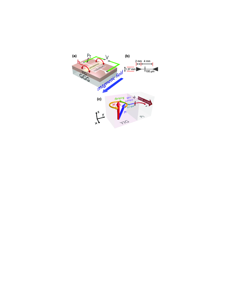
In Fig. 1(a) a schematic illustration of the investigated samples is shown. Mono-crystalline Y3Fe5O12 samples of 20, 70, 130, 200 and 300 nm thickness were deposited by means of pulsed laser deposition (PLD) from a stoichiometric target using a KrF excimer laser with a fluence of 2.6 J/cm2 and a repetition rate of 10 Hz. Ross In order to ensure epitaxial growth of the films, single crystalline substrates of gadolinium gallium garnet (Gd3Ga5O12, GGG) in the (100) orientation were used. We achieved optimal deposition conditions for a substrate temperature of 650∘C C and an oxygen pressure of 6.67 mbar. Afterwards, each film was annealed ex-situ at 820∘C C by rapid thermal annealing for 300 s under a steady flow of oxygen. This improves the crystallographic order and reduces oxygen vacancies. We determined the YIG thickness by profilometer measurements and the crystalline quality was controlled by x-ray diffraction (XRD). In order to deposit Pt onto the samples, they were transferred at atmosphere leading to possible surface adsorbates. Therefore, the YIG film surfaces were cleaned in-situ by a low power ion etching before the Pt deposition. Jungfleisch-opt We used DC sputtering under an argon pressure of 110-2 mbar at room temperature to deposit the Pt layers. XRR measurements yielded a Pt thickness of 8.5 nm, which is identical for every sample due to the simultaneously performed Pt deposition. The Pt layer was patterned by means of optical lithography and ion etching. In order to isolate the Pt stripes from the antenna we deposited a 300 nm thick square of SU-8 photoresist on the top. A sketch of the samples and the experimental setup is shown in Fig. 1(a), the dimensions of the structured Pt stripe are depicted in Fig. 1(b).
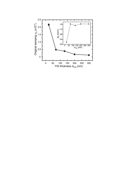
In order to corroborate the quality of the fabricated YIG samples, we performed ferromagnetic resonance (FMR) measurements using a vector network analyzer (VNA).FMR Since the area deposited by Pt is small compared to the entire sample size, we measure the damping of the bare YIG by VNA (this approach results in a small overestimate of ), whereas in the spin-pumping measurement we detect the enhanced damping of the Pt covered YIG films. The VNA-FMR results are summarized in Tab. 1 and in Fig. 2. Apparently, the 20 nm sample features the largest damping of . With increasing film thickness decreases to . There might be two reasons for the observed behavior: (1) The quality of the thinner YIG films might be worse due to the fabrication process by PLD. (2) For smaller YIG film thicknesses, the ratio between surface to volume increases. Thus, the two-magnon scattering process at the interface is more pronounced for smaller film thicknesses and gives rise to additional damping. Sparks The VNA-FMR technique yields the saturation magnetization for the YIG samples (see inset in Fig. 2 and Tab. 1). The observed values for are larger than the bulk value, Aulock ; Stancil but in agreement with the values reported for thin films. PLD_YIG The general trend of the film thickness dependence of is in agreement with the one reported in Ref. PLD_YIG ; Popova and might be associated with a lower crystal quality after the annealing.
The spin-pumping measurements for different YIG film thicknesses were performed in the following way. The samples were magnetized in the film plane by an external magnetic field H, and the magnetization dynamics was excited at a constant frequency of GHz by an Agilent E8257D microwave source. The microwave signals with powers of 1, 10, 20, 50, 100, 250 and 500 mW were applied to a 600 m wide 50 Ohm-matched Cu microstrip antenna. While the external magnetic field was swept, the ISHE-voltage was recorded at the edges of the Pt stripe using a lock-in technique with an amplitude modulation at a frequency of 500 Hz, as well as the absorbed microwave power . All measurements were performed at room temperature.
III Theoretical background
The equations describing the ferromagnetic resonance, the spin pumping and the inverse spin Hall effect are provided in the following and used in the experimental part of this paper.
III.1 Ferromagnetic resonance
In equilibrium the magnetization M in a ferromagnetic material is aligned along the bias magnetic field H. Applying an alternating microwave magnetic field perpendicularly to the external field H results in a torque on M and causes the magnetic moments in the sample to precess (see also Fig. 1(a)). In ferromagnetic resonance (FMR) the magnetic field H and the precession frequency fulfill the Kittel equation Kittel
| (1) |
where is the vacuum permeability, is the gyromagnetic ratio, is the ferromagnetic resonance field and is the saturation magnetization (experimentally obtained values of for our samples can be found in Tab. 1).
The FMR linewidth (full width at half maximum) is related to the Gilbert damping parameter asNakayama-2012 ; Burrowes ; Stancil
| (2) |
III.2 Spin pumping
By attaching a thin Pt layer to a ferromagnet, the resonance linewidth is enhanced, Tserkovnyak which accounts for an injection of a spin current from the ferromagnet into the normal metal due to the spin-pumping effect (see illustration in Fig. 1(c)). In this process the magnetization precession loses spin angular momentum, which gives rise to additional damping and, thus, to an enhanced linewidth. The effective Gilbert damping parameter for the YIG/Pt film is described as Nakayama-2012
| (3) |
where is the intrinsic damping of the bare YIG film, is the g-factor, is the Bohr magneton, is the YIG film thickness and is the real part of the effective spin mixing conductance. The effective Gilbert damping parameter is inversely proportional to the YIG film thickness : with decreasing YIG thickness the linewidth and, thus, the effective damping parameter increases.
When the system is resonantly driven in the FMR condition, a spin-polarized electron current is injected from the magnetic material (YIG) into the normal metal (Pt). In a phenomenological spin-pumping model, the DC component of the spin-current density at the interface, injected in y-direction into the Pt layer (Fig. 1(c)), can be described as Halperin ; Ando_JAP ; Nakayama-2012
| (4) |
where is the magnetization. is the z-component of , which is directed along the equilibrium axis of the magnetization (see Fig. 1(c)).
Due to spin relaxation in the normal metal (Pt) the injected spin current decays along the Pt thickness (y-direction in Fig. 1(c)) as Nakayama-2012 ; Ando_JAP
| (5) |
where is the spin-diffusion length in the Pt layer. From Eq. (4) one can deduce the spin-current density at the interface () Ando_JAP
| (6) |
Since is inversely proportional to and depends inversely on (Eq. (3)), the spin-current density at the interface increases with increasing YIG film thickness .
III.3 Inverse spin Hall effect
The Pt layer acts as a spin-current detector and transforms the spin-polarized electron current injected due to the spin-pumping effect into an electrical charge current by means of the ISHE (see Fig. 1(c)) asSaitoh-2006 ; Kajiwara ; Nakayama-2012 ; Ando_JAP ; Jungfleisch
| (7) |
where , , denote the spin Hall angle, the electron’s elementary charge and the spin-polarization vector, respectively. Averaging the charge-current density over the Pt thickness and taking into account Eqs. (4) – (7) yields
| (8) |
Taking into account Eqs. (3), (6) and (8) we calculate the theoretically expected behavior of , where is the cross section of the Pt layer. Ohm’s law connects the ISHE-voltage with the ISHE-current via =, where is the electric resistance of the Pt layer. varies between 1450 and 1850 for the different samples.
IV YIG film thickness dependence of the spin-pumping effect detected by the ISHE
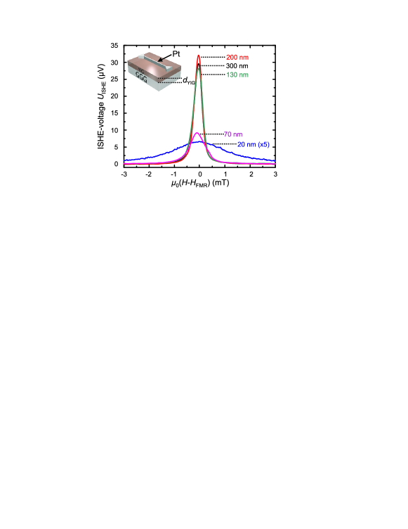
In Fig. 3 the magnetic field dependence of the generated ISHE-voltage as a function of the YIG film thickness is shown. Clearly, the maximal voltage at the resonance field and the FMR linewidth vary with the YIG film thickness. The general trend shows, that the thinner the sample the smaller is the magnitude of the observed voltage . At the same time the FMR linewidth increases with decreasing YIG film thickness.
In the following the ISHE-voltage generated by spin pumping is investigated as a function of the YIG film thickness. For these investigations we have chosen a rather small exciting microwave power of 1 mW. Thus, nonlinear effects like the FMR linewidth broadening due to nonlinear multi-magnon processes can be excluded (such processes will be discussed in Sec. V). Sec. IV.1 covers the YIG thickness dependent variation of the enhanced damping parameter . From these measurements the spin mixing conductance is deduced. In Sec. IV.2 we focus on the maximal ISHE-voltage driven by spin pumping as a function of the YIG film thickness. Finally, the spin Hall angle is determined.
IV.1 YIG film parameters as a function of the YIG film thickness
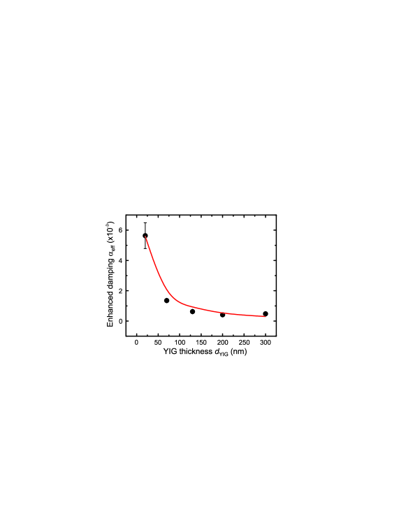
As described in Sec. III.2, the damping parameter is enhanced when a Pt layer is deposited onto the YIG film. This enhancement is investigated as a function of the YIG film thickness: the effective Gilbert damping parameter (see Eq. (3)) is obtained from a Lorentzian fit to the experimental data depicted in Fig. 3 and Eq. (2). The result is shown in Fig. 4. With decreasing YIG film thickness the linewidth and, thus, the effective damping increases. This behavior is theoretically expected: according to Eq. (3) is inversely proportional to . Since the Pt film is grown onto all YIG samples simultaneously, the spin mixing conductance at the interface is considered to be constant for all samples. Tashiro Assuming as constant and taking the saturation magnetization obtained by VNA-FMR measurements (see Fig. 2 and Tab. 1) into account, a fit to Eq. (3) yields = (7.430.36) m-2. The fit is depicted as a red solid line in Fig. 4.
IV.2 YIG thickness dependence of the ISHE-voltage driven by spin pumping
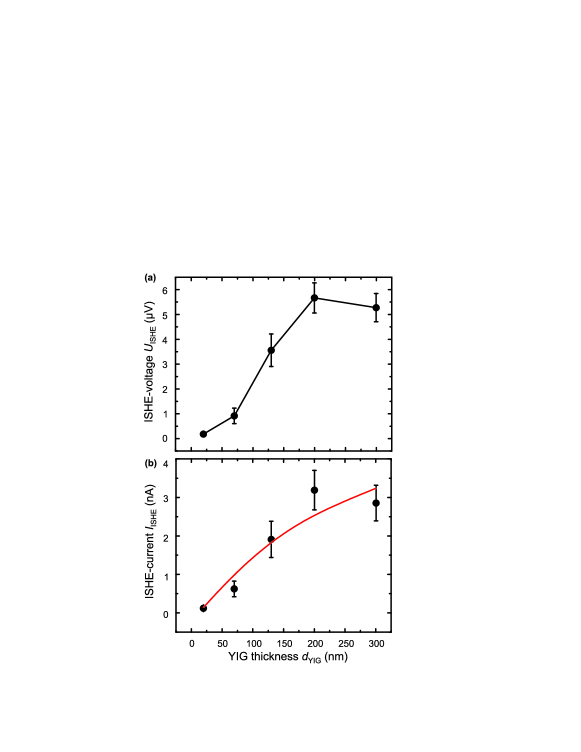
Fig. 5(a) shows the maximum voltage at the resonance field as a function of the YIG film thickness. increases up to a YIG film thickness of around 200 nm when it starts to saturate (in the case of an applied microwave power of P mW). The corresponding charge current is shown in Fig. 5(b). The observed thickness dependent behavior is in agreement with the one reported for Ni81Fe19/Pt Nakayama-2012 and for Y3Fe5O12/Pt. Tashiro With increasing YIG film thickness the generated ISHE-current increases and tends to saturate at thicknesses near 200 nm (Fig. 5(b)). According to Eq. (3), (6) and (8) it is , where is a constant. Therefore, the ISHE-current increases with increasing YIG film thickness and goes into saturation at a certain YIG thickness.
From Eqs. (3), (6) and (8) we determine the expected behavior of and compare it with our experimental data. In order to do so, the measured values for (see Tab. 1), the original damping parameter determined by VNA-FMR measurements at 1 mW (see Tab. 1) and the enhanced damping parameter obtained by spin-pumping measurements at a microwave power of 1 mW (see Fig. 4) are used. The Pt layer thickness is nm and the microwave magnetic field is determined to be A/m for an applied microwave power of 1 mW using an analytical expression. Chumakov The spin-diffusion length in Pt is taken from literature as nm Mosendz ; Kurt and the damping parameter is assumed to be constant as , which is the average of the measured values of . The fit is shown as a red solid line in Fig. 5(b). We find a spin Hall angle of , which is in agreement with literature values varying in a range of 0.0037 - 0.08. Mosendz ; Ando_PRL ; Kimura Using the fit we estimate the saturation value of the generated current. Although we observe a transition to saturation at sample thicknesses of 200 – 300 nm, we find that according to our fit, 90% of the estimated saturation level of 5 nA is reached at a sample thickness of 1.2 m.
V Influence of nonlinear effects on the spin-pumping process for varying YIG film thicknesses
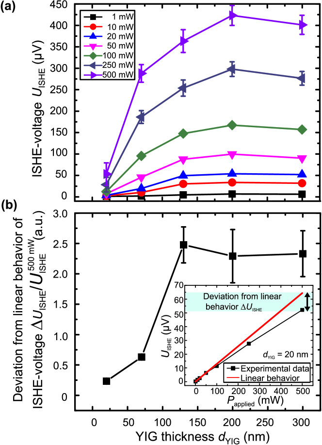
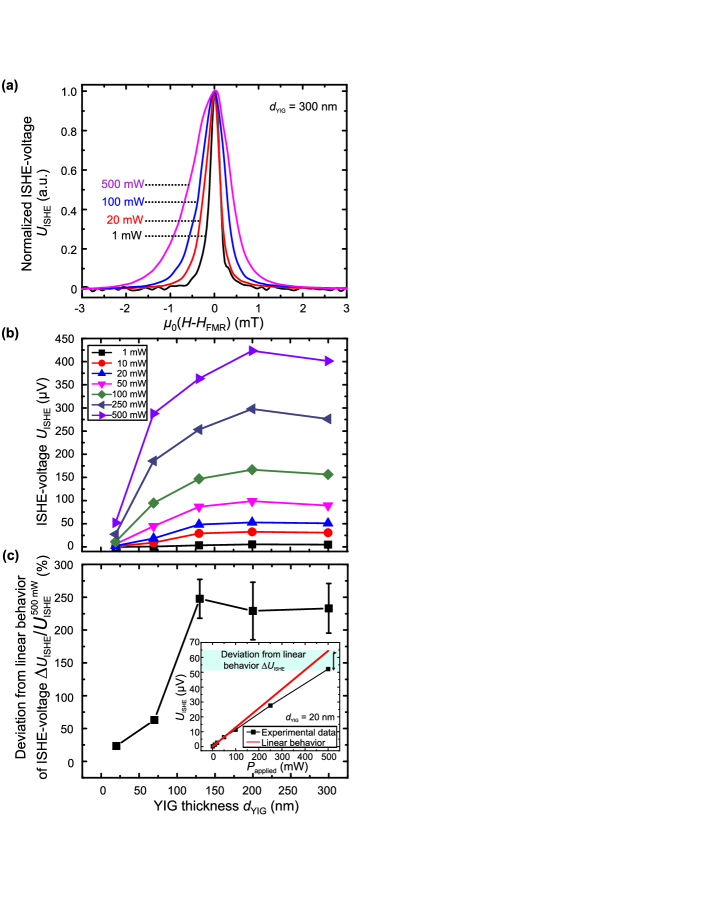
In order to investigate nonlinear effects on the spin-pumping effect for varying YIG film thicknesses, we performed microwave power dependent measurements of the ISHE-voltage as function of the film thickness . For higher microwave powers in the range of 1 mW to 500 mW we observe the same thickness-dependent behavior of the ISHE-voltage as in the linear case ( mW, discussed in Sec. IV.2): Near 200 nm starts to saturate independently of the applied microwave power, as it is shown in Fig. 6(a). Furthermore, it is clearly visible from Fig. 6(a) that for a constant film thickness the spin pumping driven ISHE-voltage increases with increasing applied microwave power. At high microwave powers the voltage does not grow linearly and saturates. Fig. 6(b) shows the deviation of the ISHE-voltage from the linear behavior with respect to the measured value of at the excitation power 500 mW. In order to obtain the relation between and for each YIG film thickness the low power regime up to 20 mW is fitted by a linear curve and extrapolated to 500 mW. The inset in Fig. 6(b) shows the corresponding viewgraph for the case of the 20 nm thick sample. As it is visible from Fig. 6(b), the deviation from the linear behavior is drastically enhanced for larger YIG thicknesses. For the thin 20 nm and 70 nm samples we observe an almost linear behavior between and over the entire microwave power range, whereas for the thicker samples the estimated linear behavior and the observed nonlinear behavior differ approximately by a factor of 2.5 (Fig. 6(b)). We observe an increase of the ISHE-voltage as well as an broadening of the FMR linewidth with increasing microwave power. In Fig. 7(a) the normalized ISHE-voltage as function of the external magnetic field is shown for different microwave powers in the range of 1 mW to 500 mW (YIG film thickness nm). The linewidth tends to be asymmetric at higher microwave powers. The shoulder at lower magnetic field is widened in comparison to the shoulder at higher fields. The reason for this asymmetry might be due to the formation of a foldover effect, Gui ; Ando_bistable due to nonlinear damping or a nonlinear frequency shift. Demidov_non-linear ; Mills
The results of the damping parameter obtained by microwave power dependent spin-pumping measurements are depicted in Fig. 7(b). It can be seen, that with increasing excitation power the Gilbert damping for thicker YIG films is drastically increased. To present this result more clearly the nonlinear damping enhancement is shown in Fig. 7(c). The damping parameter at a sample thickness of 20 nm is almost unaffected by a nonlinear broadening at high microwave powers. With increasing film thickness the original damping at mW increases by a factor of around 3 at mW. This factor is very close to the value of the deviation of the ISHE-voltage from the linear behavior (Fig. 6(b)).
This behavior can be attributed to the enhanced probability of nonlinear multi-magnon processes at larger sample thicknesses: In order to understand this, a fundamental understanding of the restrictions for multi-magnon scattering processes can be derived from the energy and momentum conservation laws:
| (9) |
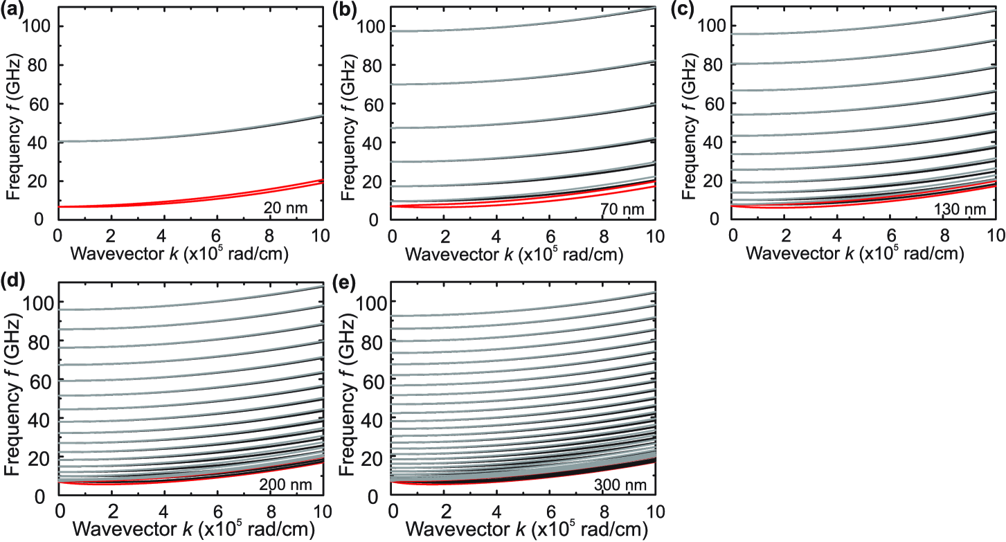
where the left/right sum of the equations runs over the initial/final magnons with indices i/j which exist before/after the scattering process, respectively. Schultheiss ; Sebastian ; BEC_nature The most probable scattering mechanism in our case is the four-magnon scattering process with and . BEC_nature In Eq. (9) the wavevector and the frequency are connected by the dispersion relation . The calculated dispersion relations are shown in Fig. 8 (backward volume magnetostatic spin-wave modes with a propagation angle as well as magnetostatic surface spin-wave modes ). DamonEshbach For this purpose, the measured values of (Tab. 1) for each sample are used. In the case of the 20 nm sample thickness, the first perpendicular standing spin-wave mode (thickness mode) lies above 40 GHz, the second above 120 GHz. Thus, the nonlinear scattering probability obeying the energy- and momentum conservation is largely reduced. This means magnons cannot find a proper scattering partner and, thus, multi-magnon processes are prohibited or at least largely suppressed. With increasing film thickness the number of standing spin-wave modes increases and, thus, the scattering probability grows. As a result, the scattering of spin waves from the initially excited uniform precession (FMR) to other modes is allowed and the relaxation of the original FMR mode is enhanced. Thus, the damping increases and we observe a broadening of the linewidth, which is equivalent to an enhanced Gilbert damping parameter at higher YIG film thicknesses (see Fig. 7).
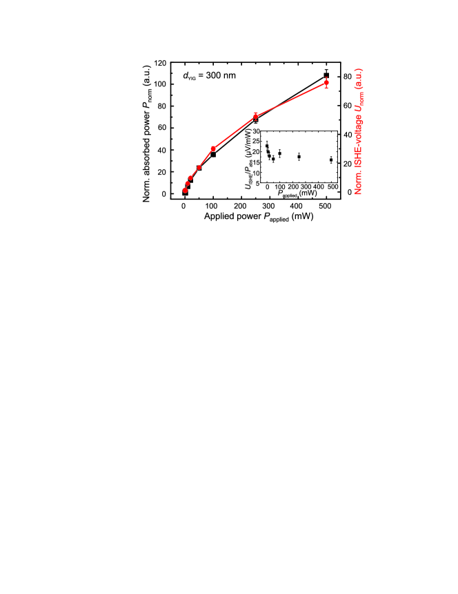
In order to investigate how the spin-pumping efficiency is affected by the applied microwave power, we measure simultaneously the generated ISHE-voltage and the transmitted (), as well as the reflected () microwave power, which enables us to determine the absorbed microwave power . Jungfleisch-opt Since the 300 nm sample exhibits a strong non-linearity (large deviation from the linear behavior (Fig. 6) and large nonlinear linewidth enhancement (Fig. 7)), we analyze this sample thickness. In Fig. 9 the normalized absorbed microwave power and the normalized ISHE-voltage in resonance are shown as a function of the applied power . Both curves tend to saturate at high microwave powers above 100 mW. The absorbed microwave power increases by a factor of 110 for applied microwave powers in the range between 1 and 500 mW, whereas the generated voltage increases by a factor of 80. The spin-pumping efficiency (see inset in Fig. 9) varies within a range of 30% for the different microwave powers without clear trend. Since the 300 nm thick film shows a nonlinear deviation of the ISHE-voltage by a factor of 2.3 (Fig. 6(b)) and the damping is enhanced by a factor of 3 in the same range of (Fig. 7(c)), we conclude that the spin-pumping process is only weakly dependent on the magnitude of the applied microwave power (see inset in Fig. 9). In our previous studies reported in Ref. Jungfleisch ; Chumak we show that secondary magnons generated in a process of multi-magnon scattering contribute to the spin-pumping process and, thus, the spin-pumping efficiency does not depend on the applied microwave power.
VI Summary
The Y3Fe5O12 thickness dependence of the spin-pumping effect detected by the ISHE has been investigated quantitatively. It is shown that the effective Gilbert damping parameter of the the YIG/Pt samples is enhanced for smaller YIG film thicknesses, which is attributed to an increase of the ratio between surface to volume and, thus, to the interface character of the spin-pumping effect. We observe a theoretically expected increase of the ISHE-voltage with increasing YIG film thickness tending to saturate above thicknesses near 200 – 300 nm. The spin mixing conductance = (7.430.36) m-2 as well as the spin Hall angle are calculated and are found to be in agreement with values reported in the literature for our materials.
The microwave power dependent measurements reveal the occurrence of nonlinear effects for the different YIG film thicknesses: for low powers, the induced voltage grows linearly with the power. At high powers, we observe a saturation of the ISHE-voltage and a deviation by a factor of 2.5 from the linear behavior. The microwave power dependent investigations of the Gilbert damping parameter by spin pumping show an enhancement by a factor of 3 at high sample thicknesses due to nonlinear effects. This enhancement of the damping is due to nonlinear scattering processes representing an additional damping channel which absorbs energy from the originally excited FMR. We have shown that the smaller the sample thickness, the less dense is the spin-wave spectrum and, thus, the less nonlinear scattering channels exist. Hence, the smallest investigated sample thicknesses (20 and 70 nm) exhibit a small deviation of the ISHE-voltage from the linear behavior and a largely reduced enhancement of the damping parameter at high excitation powers. Furthermore, we have found that the variation of the spin-pumping efficiencies for thick YIG samples which show strongly nonlinear effects is much smaller than the nonlinear enhancement of the damping. This is attributed to secondary magnons generated in a process of multi-magnon scattering that contribute to the spin pumping. It is shown, that even for thick samples (300 nm) the spin-pumping efficiency is only weakly dependent on the applied microwave power and varies only within a range of 30% for the different microwave powers without a clear trend.
Our findings provide a guideline to design and create efficient magnon- to charge current converters. Furthermore, the results are also substantial for the reversed effects: the excitation of spin waves in thin YIG/Pt bilayers by the direct spin Hall effect and the spin-transfer torque effect. Berger
VII Acknowledgments
We thank G.E.W. Bauer and V.I. Vasyuchka for valuable discussions. Financial support by the Deutsche Forschungsgemeinschaft within the project CH 1037/1-1 are gratefully acknowledged. AK would like to thank the Graduate School of Excellence Materials Science in Mainz (MAINZ) GSC 266. CAR, MCO and DHK acknowledge support from the National Science Foundation. Shared experimental facilities supported by NSF MRSEC award DMR-0819762 were used.
References
- (1) I. Žutić, J. Fabian, and S. Das Sarma, Rev. Mod. Phys. 76, 323 (2004).
- (2) S.A. Wolf, D.D. Awschalom, R.A. Buhrman, J.M. Daughton, S. von Molnár, M.L. Roukes, A.Y. Chtchelkanova, and D.M. Treger, Science 294, 1488 (2001).
- (3) Y. Tserkovnyak, A. Brataas, and G.E.W. Bauer, Phys. Rev. Lett. 88, 117601 (2002).
- (4) M.V. Costache, M. Sladkov, S.M. Watts, C.H. van der Wal, and B.J. van Wees, Phys. Rev. Lett. 97, 216603 (2006).
- (5) J.E. Hirsch, Phys. Rev. Lett. 83, 1834 (1999).
- (6) E. Saitoh, M. Ueda, H. Miyajima, and G. Tatara, Appl. Phys. Lett. 88, 182509 (2006).
- (7) Y. Kajiwara, K. Harii, S. Takahashi, J. Ohe, K. Uchida, M. Mizuguchi , H. Umezawa, H. Kawai, K. Ando, K. Takanashi, S. Maekawa, and E. Saitoh, Nature 464, 262 (2010).
- (8) C.W. Sandweg, Y. Kajiwara, A.V. Chumak, A.A. Serga, V.I. Vasyuchka, M.B. Jungfleisch, E. Saitoh, and B. Hillebrands, Phys. Rev. Lett. 106, 216601 (2011).
- (9) H. Kurebayashi, O. Dzyapko, V.E. Demidov, D. Fang, A.J. Ferguson, and S.O. Demokritov, Appl. Phys. Lett. 99, 162502 (2011).
- (10) V. Castel, N. Vlietstra, J. Ben Youssef, and B.J. van Wees, Appl. Phys. Lett. 101, 132414 (2012).
- (11) T. Tashiro, R. Takahashi, Y. Kajiwara, K. Ando, H. Nakayama, T. Yoshino, D. Kikuchi, and E. Saitoh, Proc. of SPIE 8461, 846106 (2012).
- (12) M.B. Jungfleisch, A.V. Chumak, V.I. Vasyuchka, A.A. Serga, B. Obry, H. Schultheiss, P.A. Beck, A.D. Karenowska, E. Saitoh, and B. Hillebrands, Appl. Phys. Lett. 99, 182512 (2011).
- (13) A.V. Chumak, A.A. Serga, M.B. Jungfleisch, R. Neb, D.A. Bozhko, V.S. Tiberkevich, and B. Hillebrands, Appl. Phys. Lett. 100, 082405 (2012).
- (14) X. Jia, K. Liu, K. Xia, and G.E.W. Bauer, Europhys. Lett. 96, 17005 (2011).
- (15) K. Ando, S. Takahashi, J. Ieda, Y. Kajiwara, H. Nakayama, T. Yoshino, K. Harii, Y. Fujikawa, M. Matsuo, S. Maekawa, and E. Saitoh, J. Appl. Phys. 109, 103913 (2011).
- (16) H. Nakayama, K. Ando, K. Harii, T. Yoshino, R. Takahashi, Y. Kajiwara, K. Uchida, and Y. Fujikawa, and E. Saitoh, Phys. Rev. B 85, 144408 (2012).
- (17) M.B. Jungfleisch, V. Lauer, R. Neb, A.V. Chumak, and B. Hillebrands, Appl. Phys. Lett., in print (2013).
- (18) C. Burrowes, B. Heinrich, B. Kardasz, E.A. Montoya, E. Girt, Yiyan Sun, Young-Yeal Song, and M. Wu, Appl. Phys. Lett. 101, 092403 (2012).
- (19) V. Castel, N. Vlietstra, J. Ben Youssef, and B.J. van Wees, arXiv:1304.2190v1 [cond-mat.mtrl-sci].
- (20) K. Yu. Guslienko, B.A. Ivanov, V. Novosad, Y. Otani, H. Shima, and K. Fukamichi, J. Appl. Phys. 91, 8037 (2002).
- (21) S.O. Demokritov, Spin Wave Confinement, (Pan Stanford Publishing, Singapore 2008).
- (22) The exchange correlation length is given by , where is the exchange constant and is the saturation magnetization. With erg/cm we obtain an exchange length of nm for YIG.
- (23) L. Bi, J. Hu, P. Jiang, D.H. Kim, G.F. Dionne, L.C. Kimerling, and C.A. Ross, Nature Photon. 5, 758762 (2011).
- (24) D. Chumakov, Dissertation thesis (2006).
- (25) S.S. Kalarickal, P. Krivosik, M. Wu, C.E. Patton, M.L. Schneider, P. Kabos, T.J. Silva, and J.P. Nibarger, J. Appl. Phys. 99, 093909 (2006).
- (26) M. Sparks, Ferromagnetic Relaxation Theory (McGraw-Hill, New York, 1964).
- (27) D.D. Stancil and A. Prabhakar, Spin Waves - Theory and Applications, (Springer, 2009).
- (28) W.H. Von Aulock, Handbook of Microwave Ferrite Materials (Academic, London, 1965).
- (29) N. Kumar, D.S. Misra, N. Venkataramani, S. Prasad, and R. Krishnan, J. Magn. Magn. Mater. 272, 899 (2004).
- (30) E. Popva, N. Keller, F. Gendron, L. Thomas, M.C. Brianso, M. Guyot, M. Tessier, and S.S.P. Parkin, J. Vac. Sci. Technol. A 19, 2567 (2001).
- (31) C. Kittel, Phys. Rev. 73, 155 (1948).
- (32) Y. Tserkovnyak, A. Brataas, G.E.W. Bauer, and B.I. Halperin, Rev. Mod. Phys. 77, 1375 (2005).
- (33) O. Mosendz, J.E. Pearson, F.Y. Fradin, G.E.W. Bauer, S.D. Bader, and A. Hoffmann, Phys. Rev. Lett. 104, 046601 (2010).
- (34) K. Ando, S. Takahashi, K. Harii, K. Sasage, J. Ieda, S. Maekawa, and E. Saitoh, Phys. Rev. Lett. 101, 036601 (2008).
- (35) T. Kimura, Y. Otani, T. Sato, S. Takahashi, and S. Maekawa, Phys. Rev. Lett. 98, 156601 (2007).
- (36) H. Kurt, R. Loloee, K. Eid, J.W.P. Pratt, and J. Bass, Appl. Phys. Lett. 81, 4787 (2002).
- (37) Y.S. Gui, A. Wirthmann, N. Mecking, and C.-M. Hu, Phys. Rev. B 80, 060402(R) (2009).
- (38) K. Ando and E. Saitoh, Phys. Rev. Lett. 109, 026602 (2012).
- (39) Y. Khivintsev, Bijoy Kuanr, T.J. Fal, M. Haftel, R.E. Camley, Z. Celinski, and D.L. Mills, Phys. Rev. B 81, 054436 (2010).
- (40) V.E. Demidov, H. Ulrichs, S.O. Demokritov, and S. Urazhdin, Phys. Rev. B 83, 020404(R) (2011).
- (41) H. Schultheiss, K. Vogt, and B. Hillebrands, Phys. Rev. B 86, 054414 (2012).
- (42) T. Sebastian, T. Brächer, P. Pirro, A.A. Serga, B. Hillebrands, T. Kubota, H. Naganuma, M. Oogane, and Y. Ando, Phys. Rev. Lett. 110, 067201 (2013).
- (43) S.O. Demokritov, V.E. Demidov, O. Dzyapko, G.A. Melkov, A.A. Serga, B. Hillebrands, and A.N. Slavin, Nature 443, 430 (2006).
- (44) R.W. Damon and J.R. Eshbach, J. Phys. Chem. Solids 19, 308 (1961).
- (45) J. C. Slonczewski, J. Magn. Magn. Mater. 159, L1 (1996), and L. Berger, Phys. Rev. B 54, 9353 (1996).