Thermal transport due to quantum interference in magnetic tunnel junctions
Abstract
We study the thermal transport in magnetic tunnel junctions. Thermal gradients across the tunneling barrier appear around the Fowler-Nordheim tunneling regime, due to the current-induced heat caused by quantum interference. Both thermovoltage and thermal temperature follow a linear response with the applied current, which is an evidence for a thermoelectric effect. By increasing the barrier transparency, the dynamics of thermoelectric properties is observed with the current. Accordingly, a large range of the Seebeck coefficient, 10 - 1000 , has been obtained in magnetic tunnel junctions.
pacs:
72.25.-b, 73.50.Lw, 85.35.DsI Introduction
Thermoelectric phenomena have been discovered by T.J. Seebeck one century ago. Recently, people studied thermoelectronics in spintronic devices to explore the basic physics and potential applications 1JShi ; 2MHatami ; 3KUchida ; 4GEWBauer ; 5MWalter ; 6ASlachter ; 7MCzerner ; 8NLiebing ; 9JFlipse ; 10WWLin ; 11HMYu ; 12ASlachter ; 13GEWBauer . The coupling of thermoelectronics with spintronics has generated novel research fields, such as thermoelectric effect 7MCzerner ; 8NLiebing ; 9JFlipse ; 10WWLin , thermal spin transfer torque 11HMYu , and thermally driven spin injection 12ASlachter , etc. Magnetic tunnel junctions (MTJs), spin valve structures, and ferromagnet/metal contact usually serve as probes to detect thermoelectronics. Furthermore, a heat source, e.g. a dielectric material of , is needed to generate a thermal gradient across the probe device 7MCzerner ; 8NLiebing ; 9JFlipse ; 10WWLin . Besides, the nonlocal method is also used to detect the thermoelectronic phenonmena 12ASlachter . Until now, only few reports have been used the dielectric material as the heat source directly 14ZHZhang .
An MTJ is a sandwich structure with two ferromagnetic layers separated by a thin insulating layer15MJulliere . The spin-dependent electronic transport in an MTJ is usually focused, e.g., tunneling magnetoresistance (TMR) which is defined by resistances in both parallel (PC) and anti-parallel configurations (APC) of the ferromagnetic layers (TMR = ). Previously, the voltage dependent TMR features have been explained in terms of the spin-polarized band structure and ab-inito DFT calculations for a small voltage ( )16XFHan ; 17DWang ; 18MSharma ; 19FMontaigne . As increasing the applied voltage, the barrier may become transparency for hot electrons, which is out of the direct tunneling regime20SZhang . Moreover, the Fowler-Nordheim (FN) tunneling may occur when electrons enter the conduction band of the barrier 21RFowler .
As theoretically predicted22MBStearns ; 23AHDavies , an oscillatory TMR behavior occurs along with the FN tunneling, which is attributed to the interferences of wave functions between ferromagnetic layers and the insulating barrier. In this work, MTJs with an asymmetric Al-Oxide barrier have been fabricated to fit the condition of the FN tunneling effect. We present a systematic study of thermal transport of these MTJs when the interference effect occurs24CWJBeenakker ; 25OKarlstrom . Here the tunneling barrier serves as the heat source directly and accordingly a thermal gradient across the barrier is observed due to the current-induced heat.
Here we select the Seebeck effect to study such a phenomenon. The Seebeck effect is a fundamental phenomenon of thermoelectricity, which is a field subject to extensive research during the previous decades.26RDBarnard . It normally deals with the interaction between heat transport and the charge and spin degrees of freedom. In our case, the interference effect is mainly related to the charge of electron. Even though, from the spin polarization of MTJs, one could obtain the contributions of spin-up and spin-down electrons for Seebeck coefficient. It is proved that the method involved in this work can explore thermoelectronics in MTJs 27MWilczynski .
II Experimental Details
The MTJ samples in this work were grown by using an ultrahigh vacuum (ULVAC) chamber of our magnetron sputtering system with a base pressure of Pa28ZMZeng . The sample structures have a bottom-to-top sequence known as IrMn(12)/(CoFeB)(4)/1.8 Al-oxide/CoFeB(3) (thickness in nanometers). The Al-oxide barriers were deposited by plasma oxidation with a mixture of oxygen and argon at a pressure of 1.0 Pa in a separate chamber of the same sputtering system. The barriers were fabricated in two steps to form an asymmetric oxidation barrier: the first Al layer was deposited with an under-oxidation, and the second Al was prepared with a well optimized oxidation. All the samples were patterned into ellipse-shaped junctions with the size of by conventional UV lithography. After this step, they were annealed at under vacuum for one hour. All transport measurements were performed with a four-probe technique at room temperature. The positive voltage in this work is defined as electron flow from bottom to top of MTJ stacks. Here we select two MTJs labeled as MTJ1 and MTJ2 for a detailed study.
III Results and Discussion
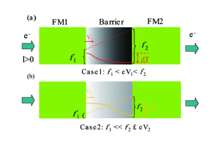
Because of the asymmetric feature of the tunneling barrier, the barrier height at the bottom ferromagnet/barrier interface is lower than at the top interface in these MTJs, as shown in Fig.1. Both and are higher than the applied voltage at both PC and APC states in the low voltage range. TMR varying with voltage mainly reflects density of states near the Fermi surface of the ferromagnetic layers29MBowen . With the increase of voltage, at two resistance states decreases, while increases, according to the fit results using the Brinkman s model30WFBrinkman . Once the applied voltage is close to or higher than , electrons appear in the barrier at the bottom interface side, resulting in a FN tunneling. The oscillatory TMR with voltage is a characteristic feature in the FN tunneling regime in MTJs 31CWMiller ; 32SHYang ; also see our data shown in Fig. 2 (a). A negative TMR is clearly observed in a certain positive voltage range (Fig. 2(c)). This suggests the FN tunneling is dominant (Case1). With further increasing voltage, the transparency of the barrier increases. Above a voltage, the barrier may behave like a spacer partly, the spin-dependent scattering appears, which coexist with the FN tunneling. After that, electrons may appear in the entire barrier with more electrons at the bottom interface side. The spin-dependent scattering enhances when the spacer - like barrier is formed (Case2 shown in Fig. 1 (b)).
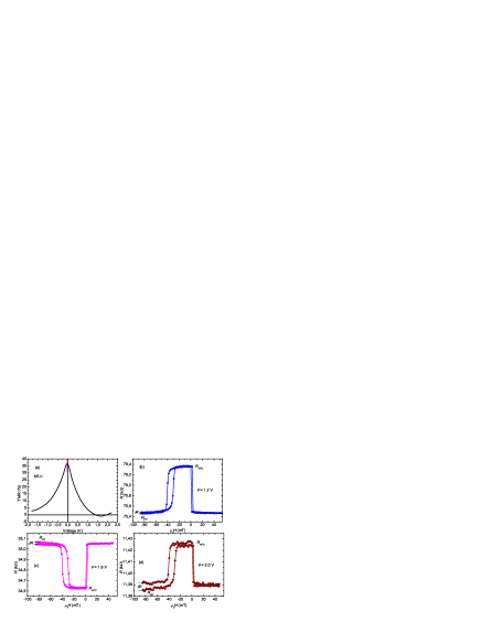
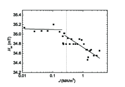
Now we discuss the heat effect in these MTJs. The interferences of the wave functions in the conduction band of the barrier with electrodes at high voltage may introduce some heat. From the current density dependence of exchange bias () of MTJ1 as shown in Fig.3, starts to decrease just before the FN tunneling occurs. The variation of exchange bias with current suggests the spin-dependent tunneling current produces a heat, which can change or revise the exchange bias 33EGapihan . At the mean while, there is a local thermal gradient across the barrier 33EGapihan , which may produce the heat during the measurements. From the curves shown in Fig.2 (b)- Fig.2 (d), a small resistance shift is found. This shift between the initial and final resistances suggests the heat appears in every loop, although the maximum current for MTJ1 is only at (corresponding to a current density of ).
We use the following equations to evaluate the thermal fluctuation of the barrier height due to the current induced heat and the corresponding thermal temperature across the barrier. For an MTJ, the temperature dependence of the junction resistance is usually explained in terms of elastic and inelastic tunneling34CHShang . The temperature dependence of the averaged conductance in the PC and APC states of MTJs is given by the following equations without considering the inelastic tunneling here 34CHShang :
| (1) |
where , is the conductance of the MTJ at zero temperature; , with the barrier thickness in angstroms and the barrier height in electron-volts; and are effective spin polarizations of two ferromagnetic electrodes. Here we use to define the shift magnitude, and the relation = n to obtain thermal temperature across the barrier. It is found that the relation between and in the PC and APC states follows by
| (2) |
assuming and because and are small. is the barrier height change due to the thermal fluctuation. For calculation, ( in the PC state) and ( in the APC state) at different voltages are fitted by the Brinkman’s model30WFBrinkman , which mainly deals with trapezoidal barriers in MTJs.
According to Eq. (1), we obtain = in the PC and APC states. Here the spin-dependent Seebeck coefficient (S) is defined as . Using and mentioned above, we obtain
| (3) |
It is obvious that S is independent of the ratio.
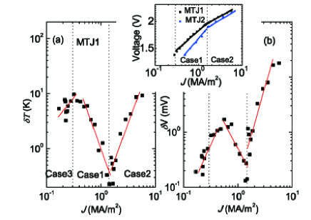
Fig. 4 (a) shows the current density dependence of the thermal temperature in the PC state for MTJ1 before and after the FN tunneling occurs. There are three distinct regions of changing with the current density. Besides two cases (Case1 and Case2) given above, in the normal tunneling regime (Case3) close to Case1 is also plotted for comparison. With the increase of current in Case3, the heat increases gradually. When the FN tunneling occurs in Case1, the heat decreases due to the increase of transparency of the barrier. However, once the spacer-like barrier becomes obvious in Case2, increases again because of the strong scattering. A range of 0.2 - 10 K is observed in Case1 and Case2, while it changes from 3.5 K to 10 K in the normal tunneling regime. Several tens or hundreds mK of have been observed in MTJs 8NLiebing ; 10WWLin . The thermovoltage is plotted as a function of the current density in Fig. 4 (b). The corresponding value ranges from 0.15 to 1.6 mV in Case1 and Case3, while it reaches 17.1mV in Case2. Clearly, varies similarly with the current density compared with due to the same power-law of . Both and reaches a maximum after the FN tunneling occurs, which may indicate the increase of transparency of the barrier is not obvious at the beginning of the FN tunneling. Besides the spin-dependent contribution, the resistance shift () includes the non spin - dependent part, both together may be responsible for and shown in Fig.4.
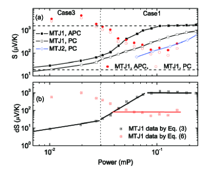
The spin-dependent thermal parameters normally scale linearly with current () in MTJs 10WWLin , spin valves 11HMYu or ferromagnet/metal contact12ASlachter . Both and show a roughly linear response in different regimes (Cases 1-3) for MTJ1. This linear relation permit us to estimate the spin-dependent Seebeck coefficient in these MTJs. The values in the PC and APC states for MTJ1 with power are given in Fig. 5 (a) (square data points). For the S calculation, we use Eq.(3) by selecting n = 1, and more discussion about n will be given below. For comparison, S in the PC state for MTJ2 is also shown (diamond data points). It is found that both MTJ1 and MTJ2 behave similarly. Because the barrier height cannot be precisely evaluated after the tunneling barrier becomes spacer-like, here we focus on the results in Case1 and Case3. It is found S and dS increase linearly with power in two cases. Here dS is the difference in S between APC and PC states, as shown in Fig.5 (b). Before more electrons appear in the tunneling barrier, S is relatively small in two resistance states, several tens of , which is similar to that in many cases 5MWalter ; 6ASlachter ; 7MCzerner ; 8NLiebing ; 10WWLin ; 14ZHZhang . At the beginning of the FN tunneling, the lowest S values of 55 in the PC state and of 83 in the APC state are obtained. Once the FN tunneling is dominant, S increases fast with power until the spacer-like barrier forms. The maximum values of 1.72 mV/K in the APC state and 0.91 mV/K in the PC state are obtained for MTJ1. Obviously, the magnitude of S can be tuned in these MTJs by the applied power, which is due to the variation in the transparency of the barrier in our case. A value of dS ranging from 9 to 1190 is obtained for MTJ1 (see center square data points in Fig. 5 (b)). The S and dS values obtained in the previous reports 7MCzerner ; 8NLiebing ; 10WWLin ; 14ZHZhang are within the range as shown in Fig.5.
Here we discuss the n value as shown in Eq. (3). The Fano effect appears due to the quantum interferences of the waves resonantly transmitted through a discrete level and those transmitted nonresonantly through continuum of states35PTrocha . Such effect is usually accompanied by shot noise36FNHooge ; 37RJSchoelkopf , which is due to the current through the device fluctuating around its average value. The shot noise is frequency independent, and its total energy is (2Fe) (=2Fe) 36FNHooge ; 37RJSchoelkopf , where e is the electron charge and F is the Fano facor. For simplicity, we select F = 1 here. In our case, the energy related to and can be given by (2eI), which corresponds to the thermal energy part in the current-induced fluctuation. If using , then is given by
| (4) |
Like , if we use the relation to define , then we obtain S as follows
| (5) |
Here S is proportional to the unit of , which is independent of voltage and barrier height. This is a character of quantum interference25OKarlstrom ; 35PTrocha . Because of n 1 when the FN tunneling occurs (see the discussion below), (n (2e), which satisfies with quantum limit 24CWJBeenakker . The barrier with asymmetric barrier heights in our MTJs can be as a qusi-quantum well especially after the FN tunneling appears, and the oscillation of TMR shown in Fig.2 (a) further proves it. In this case, the discrete levels (barrier heights) change with the applied voltage.
Without the quantum interference effect, S is small as shown in Case3 (Fig. 5). Different S obtained by Eq.(5) may imply an ability to carry electrons, which is related to . Actually if we assume , Eq.(5) is back to Eq.(3), which suggests Eq.(3) is correct only around the beginning of the FN tunneling regime where the barrier height is equal to . Moreover, we may use Eq.(5) to evaluate the n value in these MTJs since the variation of barrier height can be equal to that of voltage. It is obtained n increases from around 1 to 80, as the two black dash lines shown in Fig. 5 (a). Because of the Fano factor F 1 in the quantum regime38GIannaccone ; 39AThielmann , the maximum of (n/4) in our case will be less than 20. A value of (n/4) up to 10 has been given in Ref.25OKarlstrom .
According to Eq.(5), S is charge dependent. If considering the contribution of spin-up() and spin-down () electrons, S is equal to in the two resistance states. Because the TMR is lower than in Case1 and the corresponding spin polarization is less than , the contributions from majority and minority electrons are similar for the Seebeck coefficient S in these MTJs. and are almost half of the S value. Compared to the PC state, more scattering occurs in the APC state, which may be responsible for the big dS in Case1 in these MTJs.
Finally we use another method shown in Ref.14ZHZhang to calculate the values of S and dS for MTJ1. As suggested by Ref.14ZHZhang , to see the Seebeck effect, a linear relation in the voltage versus current density curve should be satisfied (the inset of Fig.4). The thermovoltage in this case follows:
| (6) |
here the thermal parameter is asymmetric, and the heat resistance equals to with thermal conductivity , cross-sectional area and the total thickness of the MTJ device. Because the resistance mainly comes from the insulating barrier in these MTJs, we set in the PC state and in the APC state. in our case is bias - dependent, but we use a constant (0.5) (see Fig.1). = 1.5 W/(Km) is used for during the calculation 40YSJu . The calculated results for MTJ1 in the PC and APC states are given in Fig.5 (red open and solid circle data points). Some deviation of S in two resistance states appears in the low power range because the voltage - current curve loses its linear relation (see the insert of Fig.4). The values of S and dS obtained by Eq. (6) are in the range of those obtained by Eq. (3) and Eq. (5). However, S and dS obtained in this way do not alter much with power, as indicated by the red solid line shown in Fig. 5 (b).
IV Conclusion
In this work, we take the advantage of MTJs with asymmetric oxidized Al-oxide. In the FN tunneling regime, MTJs are turned to be an oscillatory TMR effect which is reversible by voltage. The thermal fluctuation on exchange bias is observed together with FN tunneling process. Such fluctuation is induced by current induced heat around FN tunneling regime, and the fluctuation temperature increases with the applied voltage.
Furthermore, the thermal transports have been investigated in these MTJs. The tunneling barrier itself can serve as a stable thermal source in MTJs, which supplies a direct heat source for spin-dependent thermoelectric studies. It is the current-induced heat caused by quantum interference that makes the thermoelectric phenomena. The linear relation between the thermal temperature, thermovoltage and the applied current proves the thermoelectric nature. The Seebeck coefficient in these MTJs can be tuned and large, which suggests that MTJs may be a good candidate for thermoelectric application.
V Acknowledgment
This project was supported by the State Key Project of Fundamental Research of Ministry of Science and Technology [MOST, Project No. 2010CB934400 and No. 2011YQ120053] and National Natural Science Foundation [NSFC, Grant No. 11104338 and 51021061].
References
- (1) J. Shi, Kevin Pettit, E. Kita,S. S. P. Parkin, R. Nakatani and M. B. Salamon, Phys. Rev. B 54, 15273 (1996).
- (2) M. Hatami, Gerrit E.W. Bauer, Qinfang Zhang and Paul J. Kelly , Phys. Rev. Lett. 99, 066603 (2007).
- (3) K. Uchida, S. Takahashi, K. Harii, J. Ieda, W. Koshibae, K. Ando, S. Maekawa and E. Saitoh, Nature 455, 778 (2008).
- (4) G. E. W. Bauer, Allan H. MacDonald, Sadamichi Maekawa, Solid state Commun. 15, 459 (2010).
- (5) M. Walter, J. Walowski, V. Zbarsky, M. M nzenberg, M. Sch fers, D. Ebke, G. Reiss, A. Thomas, P. Peretzki, M. Seibt, J. S. Moodera, M. Czerner, M. Bachmann and C. Heiliger, Nature mater. 10, 742 (2011).
- (6) A. Slachter, Frank Lennart Bakker, and Bart Jan van Wees, Phys. Rev. B 84, 174408 (2011).
- (7) M. Czerner, Michael Bachmann, and Christian Heiliger, Phys. Rev. B 83, 132405 (2011).
- (8) N. Liebing,S. Serrano-Guisan,K. Rott, G. Reiss, J. Langer, B. Ocker, and H.W. Schumacher, Phys. Rev. Lett. 107, 177201 (2011).
- (9) J. Flipse, F. L. Bakker, A. Slachter, F. K. Dejene and B. J. vanWees, Nature Nanotech. 7, 166 (2012).
- (10) W. W. Lin, Michel Hehn, Laurent Chaput, Btrice Negulescu1, Sthane Andrieu, Franis Montaigne and Sthane Mangin, Nature Commun. DOI:10.1038/ncomms1748 (2012).
- (11) H. M. Yu, S. Granville, D. P. Yu, and J.-Ph. Ansermet, Phys. Rev. Lett. 104, 146601 (2010).
- (12) A. Slachter, F. L. Bakker, J-P. Adam and B. J. vanWees, Nature Phys. 6, 879 (2010).
- (13) G. E. W. Bauer, Eiji Saitoh and Bart J. van Wees, Nature mater. 11, 391 (2012).
- (14) Z. H. Zhang, Y. S. Gui, X. F. Lan, J. W. Cao, D. S. Xue, P. P. Freitas, D. Houddameddine, S. Hemour, K. Wu, and C. M. Hu, Phys. Rev. Lett. 109, 037206 (2012).
- (15) M. Jullire, Phys. Lett. A 54, 225 (1975).
- (16) X.F. Han, J. Murai, Y. Ando, H. Kubota, and T. Miyazaki, Appl. Phys. Lett. 78, 2533 (2001).
- (17) D. Wang, C. Nordman, J. M. Daughton, Z. Qian, and J. Fink, IEEE Tran. Magn. 40, 2269 (2004).
- (18) M. Sharma, S. X. Wang, and J.H. Nickel, Phys. Rev. Lett. 82, 616 (1999).
- (19) F. Montaigne, M. Hehn, and A. Schuhl, Phys. Rev. B 64, 144402 (2001)
- (20) S. Zhang, P. M. Levy, A. C. Marley, and S. S. P. Parkin, Phys. Rev. Lett. 79, 3744 (1997).
- (21) R. Fowler and L. Nordheim, Proc. R. Soc. London 119, 173 (1928).
- (22) M.B. Stearns, J. Magn. Magn. Mater. 5, 167 (1977).
- (23) A.H. Davies and J.M. MacLaren, J. Appl. Phys. 87, 5224 (2000).
- (24) C.W.J. Beenakker and A.A.M. Staring, Phys. Rev. B 46, 9967 (1992).
- (25) O. Karlstrom, H. Linke, G. Karlstrom, and A.Wacker, Phys. Rev. B 84, 113415 (20111).
- (26) R. D. Barnard, Thermoelectricity in Metals and Alloys (Taylor and Francis LTD., London, 1972).
- (27) M. Wilczynski, J. Phys.: Condens. Matter 23, 456001 (2011).
- (28) Z. M. Zeng, J. F. Feng, Y. Wang, X. F. Han,,* W. S. Zhan, X.-G. Zhang, and Z. Zhang, Appl. Phys. Lett. 97, 106605 (2006).
- (29) M. Bowen, A. Barthlmy, V. Bellini, M. Bibes, P. Seneor, E. Jacquet, J. P. Contour, and P. H. Dederichs, Phys. Rev. B 73, 140408 (2006).
- (30) W. F. Brinkman, R. C., Dynes, and J. M. Rowell, J. Appl. Phys. 41, 1915 (1970).
- (31) C. W. Miller, Z.-P. Li, I. K. Schuller, R. W. Dave, J. M. Slaughter, and J. Åkerman, Phys. Rev. Lett. 99, 047206 (2007).
- (32) S.-H. Yang, D.-C. Qi, A. Rusydi, H. Kawai, M. Saeys, T. Leo,D. J. Smith, and S. S. P. Parkin, Phys. Rev. Lett. 106, 167201 (2011).
- (33) E. Gapihan, J. Hault, R. C. Sousa, Y. Dahmane, B. Dieny, L. Vila, I. L. Prejbeanu, C. Ducruet, C. Portemont, K. Mackay, and J. P. Nozie, Appl. Phys. Lett. 100, 202110 (2012).
- (34) C. H. Shang, J. Nowak, R. Jansen, and J. S. Moodera, Phys. Rev. B 58, R2917 (1998).
- (35) Piotr Trocha and Jozef Barnas, Phys. Rev. B 85, 085408 (2012).
- (36) F. N. Hooge, T. G. M. Kleinpenning, and L. K. J. Vandamme, Rep. Prog. Phys., 44, 479 (1981).
- (37) R.J.Schoelkopf, P.J. Burke, A.A. Kowhevnikov, D.E. Prober, and M.J. Rooks, Phys. Rev. Lett. 78, 3370 (1997).
- (38) G. Iannaccone, G. Lombardi, M. Macucci, and B. Pellegrini, Phys. Rev. Lett. 80, 1054 (1998).
- (39) Axel Thielmann, Matthias H. Hettler, Jurgen Konig, and Gerd Schon, Phys. Rev. Lett. 95, 146806 (2005).
- (40) Y. Sungtaek Ju and M.-T. Hung, M. J. Carey, M.-C. Cyrille, and J. R. Childress, Appl. Phys. Lett. 86, 203113 (2005).