Ring-apodized vortex coronagraphs for obscured telescopes.
I. Transmissive ring apodizers.
Abstract
The vortex coronagraph (VC) is a new generation small inner working angle (IWA) coronagraph currently offered on various 8-meter class ground-based telescopes. On these observing platforms, the current level of performance is not limited by the intrinsic properties of actual vortex devices, but by wavefront control residuals and incoherent background (e.g. thermal emission of the sky) or the light diffracted by the imprint of the secondary mirror and support structures on the telescope pupil. In the particular case of unfriendly apertures (mainly large central obscuration) when very high contrast is needed (e.g. direct imaging of older exoplanets with extremely large telescopes or space-based coronagraphs), a simple VC, as most coronagraphs, can not deliver its nominal performance because of the contamination due to the diffraction from the obscured part of the pupil. Here we propose a novel yet simple concept that circumvents this problem. We combine a vortex phase mask in the image plane of a high-contrast instrument with a single pupil-based amplitude ring apodizer, tailor designed to exploit the unique convolution properties of the VC at the Lyot-stop plane. We show that such a ring-apodized vortex coronagraph (RAVC) restores the perfect attenuation property of the VC regardless of the size of the central obscuration, and for any (even) topological charge of the vortex. More importantly the RAVC maintains the IWA and conserves a fairly high throughput, which are signature properties of the VC.
Subject headings:
techniques: high angular resolution1. Introduction
The main goal of high contrast imaging is to find and, most importantly, characterize extra-solar planetary systems. Indeed, isolating the signal of exoplanets from the glare of their host star enables us to, e.g., measure and constrain their relative orbital motions with precise astrometry, characterize the planetary atmospheres through spectro-photometry, and shed some light on planet-disk interactions (see, for instance, Oppenheimer & Hinkley, 2009; Absil & Mawet, 2010; Neuhäuser & Schmidt, 2012). Coronagraphy, which is now a generic term to qualify any techniques used to improve dynamical range in images, promises to be high contrast imaging’s sharpest tool, but requires exquisite image quality and stability to perform efficiently.
The vortex coronagraph (VC, Mawet et al., 2005) is one of the most advanced coronagraphs recently brought to operational level (Mawet et al., 2011b, 2012). The VC offers small inner working angle (IWA), potentially down to the diffraction limit (), clear 360∘ off-axis field of view/discovery space, unlimited outer working angle, high throughput, intrinsic and/or induced achromaticity, operational simplicity, and compatibility with the Lyot coronagraph layout. It has also recently demonstrated raw contrast levels in the visible on the High Contrast Imaging Testbed at the Jet Propulsion Laboratory (Mawet et al., 2012, and, E. Serabyn et al. 2013, in preparation). It is also at the crux of state of the art high-contrast instruments on various 5-8 class telescopes. Since it opens a new parameter space at small separations, it has enabled recent scientific results at Palomar in the H and K bands (Mawet et al., 2010b, 2011a; Serabyn et al., 2010; Wahl et al., 2013), and at the Very Large Telescope (VLT, Mawet et al., 2013, and O. Absil et al. 2013, in preparation, and J. Milli et al. 2013, in preparation) in the L’ band. It is currently being implemented on SCExAO at Subaru (Martinache et al., 2012) and on LMIRCAM at the Large Binocular Telescope (LBT, Skrutskie et al., 2010; Esposito et al., 2011). It is also a strong candidate for an exoplanet characterization space-based mission (WFIRST-AFTA, see Spergel et al. (2013a, b); ACCESS, see Trauger et al. (2010); and SPICES, see Boccaletti et al. (2012)), for the European-Extremely Large Telescope (Mawet et al., 2012), and the Thirty-Meter Telescope.
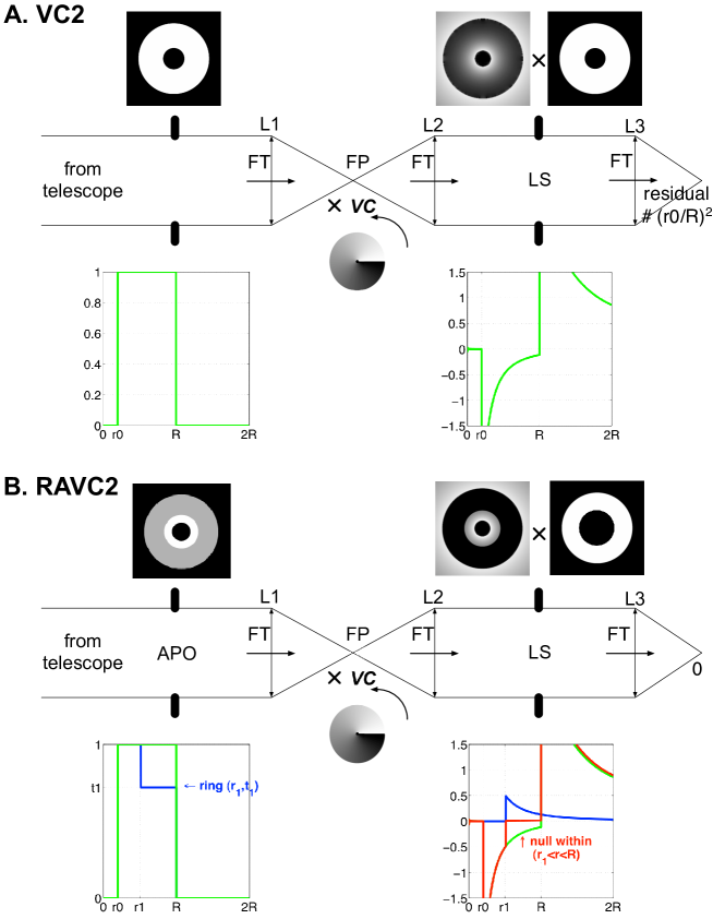
However, as for all other coronagraphs, the VC is sensitive to the aperture geometry, and particularly to secondary obscurations (Mawet et al., 2010a, 2011c). This sensitivity stems from the fact that a Vortex phase ramp in the focal plane of a telescope always diffracts light to the outer regions of circularly symmetric pupil intensity discontinuities. Thus, as expected, a single vortex will move light outside of the secondary obscuration and support structures, right into the primary pupil image (Fig. 1, A). The subsequent contrast degradation is proportional to the obscured area , with and being the radii of the central obscuration and primary mirror, respectively (Mawet et al., 2010a).
Recently we proposed a method (Mawet et al., 2011c), based on multiple vortices, that, without sacrificing throughput, reduces this residual light leakage to , with the number of coronagraph stages. This method thus enabled high contrasts to be reached even with an on-axis telescope, but at the cost of increased optical complexity, and for an imperfect result. Here we propose a new simple and elegant solution to this problem that renders the VC completely insensitive to central obscurations with a single VC stage.
Section 2 presents the principle of the ring-apodized vortex coronagraph (RAVC), starting with the charge 2 VC. Section 3 develops the charge 4 case, while Section 4 lays out the basis for a generalization to higher order VCs. In Section 5, we discuss the various trade-offs between sensitivity to low-order aberrations, stellar size and throughput. Section 6 presents current high-performing technical solutions to manufacture the VC, the apodizer, and to mitigate the diffraction from the support structures, demonstrating the RAVC’s high level of technology readiness. Section 7 summarizes the concept principles and puts it into the context of future Extremely Large Telescopes (ELT) and space-based missions.
2. Principle of the RAVC
The ring-apodized vortex coronagraph (RAVC) is based on the superposition principle and the vortex properties of moving light in and out of circular apertures. Its principle relies on modulating the entrance pupil with one (or a set of) concentric ring(s) of well chosen size(s) and transmittance(s), in order to yield perfect cancellation of on-axis sources at the Lyot stop level. In the following, we show that perfect solutions can be found for any topological charge. We will start with the case of topological charge 2 RAVC, and detail the derivation for charge 4 RAVC in the next section. We finally generalize this concept for arbitrary topological charges in Section 4.
2.1. The simple case of charge 2 RAVC
The effect of a charge vortex phase ramp, , applied to the ideal focal plane field (Airy pattern), , of a filled circular aperture of radius , where k is the wavenumber and is the radial coordinate in the focal plane, has been calculated analytically by various authors (Mawet et al., 2005; Jenkins, 2008; Swartzlander, 2009; Carlotti et al., 2009). The Fourier transform of focal plane electrical field gives the field in the pupil plane downstream from the coronagraph (Lyot-stop plane). Dropping the azimuthal phase term, this transform yields:
| (1) |
Using the superposition principle, a centrally obscured pupil can be seen as the difference between a filled pupil of radius and a smaller filled pupil of radius , yielding a pupil field after the topological charge 2 vortex of (Mawet et al., 2011c)
| (2) |
The Lyot stop then blocks everything for , so from now on, we will not consider this area anymore in order to focus on the region of interest, i.e. . Indeed, the residual field interior to the pupil (between and ) leads to contrast degradation in the subsequent focal plane image, as the fraction of the total energy remaining inside the pupil is , or for a central obscuration.
Consider now that the entrance pupil has an additional ring with from , such that , to the outer radius , and characterized by an amplitude transmission coefficient for . Note that the interior of the ring, , has a transmission . Using the same reasoning, we now have within the Lyot plane after the charge 2 vortex
| (3) |
It appears clearly that the degrees of freedom introduced by the ring apodizer (namely its size , and transmittance ) provide enough leverage to completely cancel the light within . Indeed if
| (4) |
then the field in the Lyot plane for is completely nulled. Fig. 1, B shows 1-dimensional calculations and 2-dimensional simulations where, as expected, the vortex fields issued from the central obscuration and the ring perfectly balance and cancel each other at the Lyot plane, between and downstream from the VC (see also Fig. 2). The single Lyot stop is then designed to block the light for , thus effectively increasing the size of the final central obstruction, and of course for .

2.2. Throughput optimization
There is a whole set of solutions to Eq. 4 with and . However, the best solution will maximize the throughput for a given . is defined as the energy going through the ring , normalized by the energy nominally transmitted by the centrally obscured telescope aperture, or
| (5) |
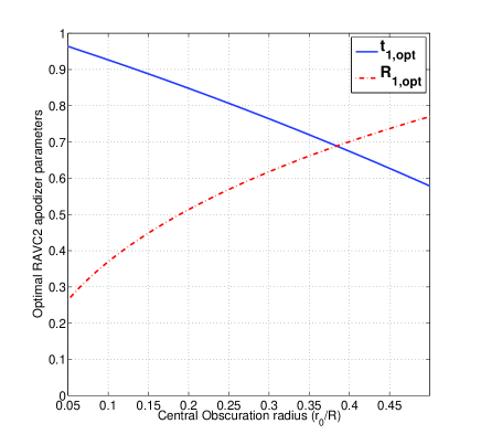
Substituting Eq. 4 into Eq. 5, and differentiating T with respect to , we find the optimal ring parameters associated with a charge 2 VC
| (6) |
where , and are the relative radii. Note that and are functions of only (see Fig. 3), which is remarkably analogous to the problem associated to designing apodizers for apodized pupil Lyot coronagraphs (APLC) with hard edge focal plane masks (Soummer, 2005). Indeed, in both cases, there only exists a unique apodizer configuration that maximizes throughput while yielding a chosen level of starlight extinction. However due to the nature of the VC, this optimal solution turns out to rely on sharp variation of the amplitude profile while the optimal solutions for an APLC are smooth.
3. Charge 4 RAVC
The charge 2 RAVC design is simple and the analytical solution very easy to find. The cancellation of the field at the Lyot stop within the outer ring, and the throughput maximization provides two equations that fully and unambiguously characterize the apodizer’s two free parameters. The charge 4 case is similar in nature but slightly less trivial.
3.1. Two rings for perfect cancellation
As the topological charge of the VC increases, so does the complexity of its response at the Lyot stop plane. Following Mawet et al. (2005) and Carlotti et al. (2009), for a topological charge 4 vortex, we have
| (7) |
The amplitude function after the vortex is now a polynomial of order , following the topological charge of the vortex. This function is not self-similar anymore, even though each individual term is. For the sake of simplicity, let us rename this polynomial
| (8) |
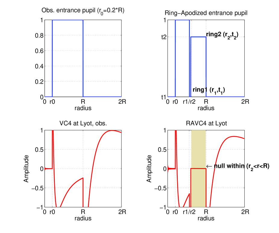
A single additional ring will not provide enough leverage to cancel both terms, so we will now consider adding a second ring with from , such that , to the radius , and characterized by an amplitude transmission coefficient for . Note that the first ring is now of inner radius , such that and outer radius , and characterized by an amplitude transmission coefficient for . Note that the interior of the first ring, , still has a transmission .
Using the same reasoning as before, we now have within the Lyot plane after the charge 4 vortex, and this double ring apodizer
| (9) |
We are now seeking solutions that perfectly cancel the light within the outer ring , using the four free parameters constraining the ring sizes and transmittances, i.e. and .
| (10) |
Finding solutions to this under-constrained problem is not straightforward as the functions are not self similar. However, by separating the quadratic and fourth order terms, and, since , we can rewrite Eq. 10 as
| (11) |
Eq. 11 is a system of two equations with 4 unknowns.
3.2. Throughput optimization
In order to better constrain the set of possible solutions, we once again introduce throughput as our figure of merit, but now is defined as the energy going through the ring .
| (12) |
Closer examination of the throughput expression indicates that optimal solutions are solutions that maximize the outer ring transmittance while keeping as small as possible. Cascading both constraints down to Eq. 11, it is easy to derive that such a condition is met for . Indeed, with , the modulation terms in and introduced by the rings to balance the central obscuration terms, have maximum weights. Setting allows us to simplify the equations greatly, yielding the following charge 4 ring-apodized VC fundamental formulae for optimal throughput
| (13) |
where , , , are the radii relative to the entrance pupil outer radius . Fig. 4 shows the perfect cancellation of the RAVC4 fields at the Lyot within . One can also explore the entire parameter space by solving numerically the following optimization problem:
| (14) | |||
| (17) |
This optimization naturally yields solutions for which , for all sizes of central obscurations.
4. Generalization to higher (even) topological charges
After detailing the design of charge 2 and 4 RAVCs, for which simple closed form analytical expressions of the apodizer critical dimensioning parameters can be found, we now generalize the concept of the RAVC to higher topological charges.
4.1. The number of rings is equal to half the charge
From Carlotti et al. (2009), we know that for a vortex of topological charge , the vortex function at the Lyot-stop plane downstream from the coronagraph can be written
| (18) |
where is the radial Zernike polynomial normalized so that . The real-valued coefficients are computed from the radial Zernike polynomials with, e.g., for , and for (see Carlotti et al. (2009) for additional details). Thus the field diffracted in the Lyot plane by the imprint of the central obscuration is always a radial polynomial of order . As a consequence this polynomial can be perfectly nulled if the coefficient associated with each order is zero. Designing an apodizer with concentric rings, with and , provides enough lever arm to achieve this perfect cancellation. The equations driving the design of the apodizer are then:
| (19) |
4.2. Throughput optimization
For the case of an arbitrary charge vortex it becomes quite challenging to a-priori simplify the problem by setting the transmittance of one or several rings to zero, as we did in the case of a charge 4 RAVC. However finding the optimal ring design with respect to throughput optimization can be easily carried out by extending the methodology presented in Equation 14. Indeed The throughput is always a function of the outer ring diameter and transmittance , as follows
| (20) |
One can the explore the entire parameter space by solving the following optimization problem:
| (21) | |||
Solving this system of equations for the and is non trivial for higher topological charges, and requires numerical optimization methods. We have verified the existence of solutions for charges up to .
5. Performances
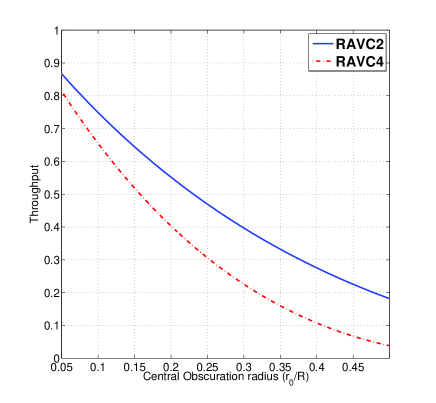
Here we discuss the performance of the RAVC family in terms of contrast, (off-axis) throughput, and inner working angle. For perfect optics and perfect VCs of various (even) topological charges, there exists RAVC solutions providing infinite contrast whatever the central obscuration. Throughput is a decreasing function of the topological charge and central obscuration size (see Eq. 20). Indeed, throughput is always a function of the outer ring area, which gets smaller when the charge increases (more rings necessary) and of course when the central obscuration gets larger.
Higher topological charges , which trade off inner working angle (e.g. IWA, IWA), are desired when the telescope size increases (to mitigate the stellar size effect) or when sensitivity to low-order aberrations becomes the limiting factor (Mawet et al., 2010a). Indeed, Jenkins (2008) showed that the sensitivity of the VC to pointing offsets , in units of , is proportional to , with (the same laws apply to the sensitivity to stellar size, which can be seen as an incoherent sum of pointing offsets).
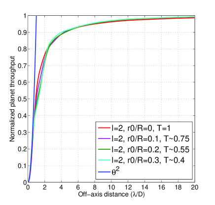
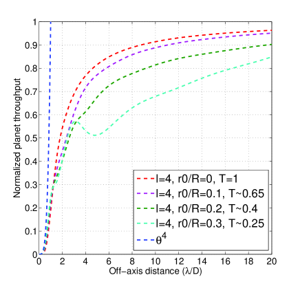
Fig. 5 presents a throughput curve for the RAVC2 and RAVC4, as a function of central obscuration size. For a central obscuration, the RAVC2 throughput is and for the RAVC4. For , the RAVC2 throughput is and for the RAVC4. Note that the IWA of the VC, classically defined as the off-axis throughput point (relative to the maximum), is not affected by the apodizer in the topological charge 2 case (see Fig. 6, left), but marginally affected for the charge 4 case (see Fig. 6, right), especially as the size of the central obscuration increases.
The RAVC solution is thus a good compromise between the numerically-optimized apodizer masks presented in Carlotti et al. 2013 (in preparation, see also Section 6.5) as it has comparable throughput but with a full search area, and the Phase-Induced Amplitude Apodization Complex Mask Coronagraph (PIAACMC, Guyon et al., 2013), which involves more complicated optics.
6. Technical feasibility
In this section we discuss the technical feasibility of the RAVC, from the current technology readiness of the VC to the ring apodizer manufacturability and the optical layout of the concept, including three practical solutions to mitigate the diffraction from the secondary support structures.
6.1. Vortex mask manufacturing
The vector vortex coronagraph (VVC, Mawet et al., 2005, 2009) is one possible and easy route to manufacture VCs111Noteworthy progress was recently made in the scalar vortex technology, here using computer generated holograms, see Errmann et al. (2013).. It advantageously makes use of the geometrical or Pancharatnam-Berry phase, which is achromatic by nature. The VVC is based on a space-variant halfwave plates (HWP), circularly symmetric in the charge 2 case. Manufacturing the VVC thus requires manipulating the polarization vector in a space-variant manner, i.e. it needs to be significantly modulated across spatial scales of less than a mm, with precisions of a few microns and fractions of a degree. Three technological approaches are currently used to manufacture the VVC (Mawet et al., 2012): liquid crystal polymers (Mawet et al., 2009), subwavelength gratings (Mawet et al., 2005; Delacroix et al., 2013), and photonic crystals (Murakami et al., 2010, 2013). Each one of these technological choices has advantages and drawbacks, enumerated in Mawet et al. (2012), and practical vortex devices that have already provided very high contrast with unobscured apertures are already available (see Table 1). Thus we now turn to the manufacture of the new component needed, i.e., the ring apodizer .
| Tech. | Cent. def. | Raw Contrast | ||
|---|---|---|---|---|
| LCP | VIS-NIR | 2-4 | m (aaManuf. by JDSU (Mawet et al., 2009, 2012), see also Serabyn et al. 2013, in preparation.) | @ 785 nm |
| m (bbManuf. by BeamCo (Nersisyan et al., 2013).) | 10% BW | |||
| 20% BW | ||||
| PC | VIS(-NIR) | 2 | m (ccManuf. by Photonic Lattice Inc. (Murakami et al., 2010, 2013).) | @ 785 nm |
| SG | (NIR-)MIR | 2 | m (ddManuf. by Uppsala University (Delacroix et al., 2013)) | @ 4 m (eeWithout wavefront control.) |
6.2. Apodizing Mask manufacturing
Given the extreme simplicity of the ring apodized masks, and their discrete levels of transmittance, no difficulty is foreseen in this area. The manufacturing of the ring apodizer pupil mask should thus be straightforward and one can envision using either microdot or optical coating technologies.
The microdot technology uses a halftone-dot process, where the relative density of a binary array of pixels (transmission of 0 or 1 at the micron level) is calculated to obtain the required local transmission (here uniform within the rings). The manufacturing of current apodized pupil Lyot coronagraphs (Soummer, 2005; Soummer et al., 2011) for SPHERE (Kasper et al., 2012) and GPI (Macintosh et al., 2008) uses the microdot technology which is well mastered (Martinez et al., 2009a, b). Note the band-limited coronagraphs of NIRCAM soon to fly aboard JWST have also made use of a similar technique (Krist et al., 2009). The demonstrated advantages of microdot apodizers are numerous: 1%-level accuracy on the transmission profile, achromatic in phase and amplitude, compatibility with a wide range of substrate material, and with conventional AR coating. Spatial phase distortion are in principle absent (Martinez et al., 2009a, b), but careful control will be necessary for the RAVC. Indeed, the perfect superposition of the fields originating from the central obscuration and the ring(s) requires a uniform phase across the apodizer area.
Another potential technique could make use of optical coatings. Trauger et al. (2012) developed a successful method to induce a quasi-achromatic spatially variable optical density with a combination of a deposited metal together with a dielectric to cancel the induced phase shift. This technology has been used to manufacture the band-limited coronagraph currently holder of the contrast world record (Trauger et al., 2011), and spatial transitions of the order of a few microns should be possible.
6.3. RAVC Layout
The RAVC layout is quite simple and only requires the insertion of the apodizer at a pupil plane upstream of the coronagraph (see Fig. 1, B). Provided that the pupil plane can be shared with a potential deformable mirror, or that the deformable mirror can be slightly out of the pupil plane, no additional stage is required (Mawet et al., 2011c). Such a configuration allows implementing the RAVC on existing ground-based instruments with little additional effort as wheels with pupil masks are most of the time available.
6.4. Strut mitigation with ACAD
The analytical solutions presented above only deals with a central on-axis obscuration. Large telescope apertures rarely resemble uniform disks, or annuli. Besides the central obscuration, they usually feature opaque areas produced for example by their support structures or gaps between main mirror segments. Following the superposition principle, such opaque areas diffract light in the same way but with opposite phase. The resulting PSF structure produced by opaque areas can be detrimental to high-contrast imaging, and the total scattered flux is proportional to the size of the obscured area.
Secondary mirror spiders produce extended spike-shaped features, and the net-like gap structure of a segmented mirror produces a regular speckle pattern with a pitch that is inversely proportional to the segment pitch. An efficient diffraction control system has to take aperture irregularities into account. Conventional Apodizers have been calculated for irregular apertures (Carlotti et al., 2011), and are now optimized to deal with phase mask coronagraphs (see Sect. 6.5 below, and Carlotti, 2013).
An interesting alternative to classical apodization techniques is the upfront correction of aperture irregularities by optical remapping in the geometric and thus achromatic regime. While PIAA can remove central obscurations, Pueyo & Norman (2012) presented a method (ACAD, Active Correction of Aperture Discontinuities) to derive mirror shapes suitable to remove the narrow structures introduced by spiders, gaps and maybe even missing segments. Because the required mirror deformations are small and of the order of a few microns, deformable mirrors (DMs) could be used for this purpose.
Even without apodization or remapping, PSF structures produced by gaps and spiders are typically less localized and less affected by the coronagraphic mask. Therefore, they show up mostly as bright structures of the original geometry in the Lyot plane of an efficient coronagraph and can be masked to a large extent by a suitable irregularly shaped Lyot stop. For larger separations the fraction of the field of view spoiled by spiders and gaps may be sufficiently small to ignore.
6.5. Strut mitigation by apodizer optimization
If two DMs are available, ACAD can be used to mitigate the diffraction effects due to the struts. However, if there is only one DM available, or no DMs at all, this task can be given to a different type of apodizer, specifically computed to take these additional diffraction effects into account. Following an idea first presented in Carlotti (2013), and then applied to the case of the four-quadrant phase mask, the 2D transmission of amplitude apodizers can be maximized in a numerical optimization problem, where constraints are set on the extremum values of the electric field in the Lyot plane.
An upcoming paper (A. Carlotti et al. 2013b, in preparation) presents charge-2 and charge-4 VC apodizers designed for several on-axis telescopes with 10-30% central obscurations and orthogonal spiders. Interestingly, the overall morphology of these numerically optimized solutions converges to the analytical RAVC design for the ideal strut-less pupil, and departs from it only around the struts, where additional local apodization features are necessary. While slightly smaller, the transmissions of these apodized coronagraphs are also comparable to the transmissions of the RAVC2 and RAVC4. This is mostly due to the presence of the secondary supports in the pupil, but also partially explained by the finite radius imposed to the vortex phase mask (currently limited to 32-64 because of the complexity of the computations). As other 2D optimal apodizers, these masks have binary transmissions, and can thus be manufactured the same way the shaped pupil coronagraph (SPC, Kasdin et al., 2007) was manufactured, i.e. using Deep Reactive Ion Etching (DRIE) of a Silicon-On-Insulator (SOI) wafer. The fabrication of binary apodizers can also make use of the microdots and coating technologies, as discussed in Section 6.2.
Another straightforward strut mitigation technique is the spider removal plate (SRP) which removes the strut footprint by translating the clear and contiguous parts of the pupil inwards with tilted plane-parallel plates (Lozi et al., 2009). This solution is however less ideal for very high contrast applications since it introduces a thick prismatic optical element in the beam upstream of the coronagraph, and with it, its share of chromatic optical aberrations.
7. Conclusions : a game-changing concept
The ring-apodized vortex coronagraph (RAVC) is a game-changing concept. It unambiguously solves the last hurdle that the VC faced, namely its sensitivity to central obscuration. Contrary to previous solutions which were relying on multi-stage approaches (Mawet et al., 2011c) or complex numerically optimized apodization solutions (Carlotti, 2013), the RAVC is a single stage approach with extremely simple apodizer designs. The simplicity of the RAVC concept enables fast track implementation.
The concept is particularly relevant to future extreme adaptive optics instruments for Extremely Large Telescopes (ELT) and coronagraphic space missions employing on-axis telescopes, where central obscuration and the desired use of topological charge 4 VC are additional constraints that the RAVC family solves pragmatically. With a more limited aperture in space, throughput loss might be an issue. However, a forthcoming paper (Pueyo et al. 2013, in preparation) will extend the RAVC concept to lossless apodization techniques, which should mitigate this problem as well.
References
- REV (????) ????
- 08 (1) 08. 1
- Absil & Mawet (2010) Absil, O., & Mawet, D. 2010, A&A Rev., 18, 317
- Boccaletti et al. (2012) Boccaletti, A., Schneider, J., Traub, W., Lagage, P.-O., Stam, D., Gratton, R., Trauger, J., Cahoy, K., Snik, F., Baudoz, P., Galicher, R., Reess, J.-M., Mawet, D., Augereau, J.-C., Patience, J., Kuchner, M., Wyatt, M., Pantin, E., Maire, A.-L., Vérinaud, C., Ronayette, S., Dubreuil, D., Min, M., Rodenhuis, M., Mesa, D., Belikov, R., Guyon, O., Tamura, M., Murakami, N., & Beerer, I. M. 2012, Experimental Astronomy, 34, 355
- Carlotti (2013) Carlotti, A. 2013, A&A, 551, A10
- Carlotti et al. (2009) Carlotti, A., Ricort, G., & Aime, C. 2009, A&A, 504, 663
- Carlotti et al. (2011) Carlotti, A., Vanderbei, R., & Kasdin, N. J. 2011, Optics Express, 19, 26796
- Delacroix et al. (2013) Delacroix, C., Absil, O., Forsberg, P., Mawet, D., Christiaens, V., Karlsson, M., Boccaletti, A., Baudoz, P., Kuittinen, M., Vartiainen, I., Surdej, J., & Habraken, S. 2013, A&A, 553, A98
- Errmann et al. (2013) Errmann, R., Minardi, S., & Pertsch, T. 2013, ArXiv e-prints
- Esposito et al. (2011) Esposito, S., Riccardi, A., Pinna, E., Puglisi, A., Quirós-Pacheco, F., Arcidiacono, C., Xompero, M., Briguglio, R., Agapito, G., Busoni, L., Fini, L., Argomedo, J., Gherardi, A., Brusa, G., Miller, D., Guerra, J. C., Stefanini, P., & Salinari, P. 2011, in Proc. SPIE, Vol. 8149
- Guyon et al. (2013) Guyon, O., Hinz, P. H., Cady, E., Belikov, R., & Martinache, F. 2013, ArXiv e-prints
- Jenkins (2008) Jenkins, C. 2008, MNRAS, 384, 515
- Kasdin et al. (2007) Kasdin, N. J., Vanderbei, R. J., & Belikov, R. 2007, Comptes Rendus Physique, 8, 312
- Kasper et al. (2012) Kasper, M., Beuzit, J.-L., Feldt, M., Dohlen, K., Mouillet, D., Puget, P., Wildi, F., Abe, L., Baruffolo, A., Baudoz, P., Bazzon, A., Boccaletti, A., Brast, R., Buey, T., Chesneau, O., Claudi, R., Costille, A., Delboulbé, A., Desidera, S., Dominik, C., Dorn, R., Downing, M., Feautrier, P., Fedrigo, E., Fusco, T., Girard, J., Giro, E., Gluck, L., Gonte, F., Gojak, D., Gratton, R., Henning, T., Hubin, N., Lagrange, A.-M., Langlois, M., Mignant, D. L., Lizon, J.-L., Lilley, P., Madec, F., Magnard, Y., Martinez, P., Mawet, D., Mesa, D., Müller-Nilsson, O., Moulin, T., Moutou, C., O’Neal, J., Pavlov, A., Perret, D., Petit, C., Popovic, D., Pragt, J., Rabou, P., Rochat, S., Roelfsema, R., Salasnich, B., Sauvage, J.-F., Schmid, H. M., Schuhler, N., Sevin, A., Siebenmorgen, R., Soenke, C., Stadler, E., Suarez, M., Turatto, M., Udry, S., Vigan, A., & Zins, G. 2012, The Messenger, 149, 17
- Krist et al. (2009) Krist, J. E., Balasubramanian, K., Beichman, C. A., Echternach, P. M., Green, J. J., Liewer, K. M., Muller, R. E., Serabyn, E., Shaklan, S. B., Trauger, J. T., Wilson, D. W., Horner, S. D., Mao, Y., Somerstein, S. F., Vasudevan, G., Kelly, D. M., & Rieke, M. J. 2009, in Society of Photo-Optical Instrumentation Engineers (SPIE) Conference Series, Vol. 7440, Society of Photo-Optical Instrumentation Engineers (SPIE) Conference Series
- Lozi et al. (2009) Lozi, J., Martinache, F., & Guyon, O. 2009, PASP, 121, 1232
- Macintosh et al. (2008) Macintosh, B. A., Graham, J. R., Palmer, D. W., Doyon, R., Dunn, J., Gavel, D. T., Larkin, J., Oppenheimer, B., Saddlemyer, L., Sivaramakrishnan, A., Wallace, J. K., Bauman, B., Erickson, D. A., Marois, C., Poyneer, L. A., & Soummer, R. 2008, Adaptive Optics Systems. Edited by Hubin, 7015, 31
- Martinache et al. (2012) Martinache, F., Guyon, O., Clergeon, C., Garrel, V., & Blain, C. 2012, in Proc. SPIE, Vol. 8447
- Martinez et al. (2009a) Martinez, P., Dorrer, C., Aller Carpentier, E., Kasper, M., Boccaletti, A., Dohlen, K., & Yaitskova, N. 2009a, A&A, 495, 363
- Martinez et al. (2009b) Martinez, P., Dorrer, C., Kasper, M., Boccaletti, A., & Dohlen, K. 2009b, A&A, 500, 1281
- Mawet et al. (2013) Mawet, D., Absil, O., Delacroix, C., Girard, J. H., Milli, J., O’Neal, J., Baudoz, P., Boccaletti, A., Bourget, P., Christiaens, V., Forsberg, P., Gonte, F., Habraken, S., Hanot, C., Karlsson, M., Kasper, M., Lizon, J.-L., Muzic, K., Olivier, R., Peña, E., Slusarenko, N., Tacconi-Garman, L. E., & Surdej, J. 2013, A&A, 552, L13
- Mawet et al. (2011a) Mawet, D., Mennesson, B., Serabyn, E., Stapelfeldt, K., & Absil, O. 2011a, ApJ, 738, L12
- Mawet et al. (2011b) Mawet, D., Murakami, N., Delacroix, C., Serabyn, E., Absil, O., Baba, N., Baudrand, J., Boccaletti, A., Burruss, R., Chipman, R., Forsberg, P., Habraken, S., Hamaguchi, S., Hanot, C., Ise, A., Karlsson, M., Kern, B., Krist, J., Kuhnert, A., Levine, M., Liewer, K., McClain, S., McEldowney, S., Mennesson, B., Moody, D., Murakami, H., Niessner, A., Nishikawa, J., O’Brien, N., Oka, K., Park, P., Piron, P., Pueyo, L., Riaud, P., Sakamoto, M., Tamura, M., Trauger, J., Shemo, D., Surdej, J., Tabirian, N., Traub, W., Wallace, J., & Yokochi, K. 2011b, in Society of Photo-Optical Instrumentation Engineers (SPIE) Conference Series, Vol. 8151, Society of Photo-Optical Instrumentation Engineers (SPIE) Conference Series
- Mawet et al. (2012) Mawet, D., Pueyo, L., Lawson, P., Mugnier, L., Traub, W., Boccaletti, A., Trauger, J. T., Gladysz, S., Serabyn, E., Milli, J., Belikov, R., Kasper, M., Baudoz, P., Macintosh, B., Marois, C., Oppenheimer, B., Barrett, H., Beuzit, J.-L., Devaney, N., Girard, J., Guyon, O., Krist, J., Mennesson, B., Mouillet, D., Murakami, N., Poyneer, L., Savransky, D., Vérinaud, C., & Wallace, J. K. 2012, in Proc. SPIE, Vol. 8442
- Mawet et al. (2010a) Mawet, D., Pueyo, L., Moody, D., Krist, J., & Serabyn, E. 2010a, in Society of Photo-Optical Instrumentation Engineers (SPIE) Conference Series, Vol. 7739, Society of Photo-Optical Instrumentation Engineers (SPIE) Conference Series
- Mawet et al. (2005) Mawet, D., Riaud, P., Absil, O., & Surdej, J. 2005, ApJ, 633, 1191
- Mawet et al. (2010b) Mawet, D., Serabyn, E., Liewer, K., Burruss, R., Hickey, J., & Shemo, D. 2010b, ApJ, 709, 53
- Mawet et al. (2009) Mawet, D., Serabyn, E., Liewer, K., Hanot, C., McEldowney, S., Shemo, D., & O’Brien, N. 2009, Optics Express, 17, 1902
- Mawet et al. (2011c) Mawet, D., Serabyn, E., Wallace, J. K., & Pueyo, L. 2011c, Optics Letters, 36, 1506
- Murakami et al. (2013) Murakami, N., Hamaguchi, S., Sakamoto, M., Fukumoto, R., Ise, A., Oka, K., Baba, N., & Tamura, M. 2013, Optics Express, 21, 7400
- Murakami et al. (2010) Murakami, N., Nishikawa, J., Yokochi, K., Tamura, M., Baba, N., & Abe, L. 2010, ApJ, 714, 772
- Nersisyan et al. (2013) Nersisyan, S. R., Tabiryan, N. V., Mawet, D., & Serabyn, E. 2013, Optics Express, 21, 8205
- Neuhäuser & Schmidt (2012) Neuhäuser, R., & Schmidt, T. O. B. 2012, ArXiv e-prints
- Oppenheimer & Hinkley (2009) Oppenheimer, B. R., & Hinkley, S. 2009, ARA&A, 47, 253
- Pueyo & Norman (2012) Pueyo, L., & Norman, C. 2012, ArXiv e-prints
- Serabyn et al. (2010) Serabyn, E., Mawet, D., & Burruss, R. 2010, Nature, 464, 1018
- Skrutskie et al. (2010) Skrutskie, M. F., Jones, T., Hinz, P., Garnavich, P., Wilson, J., Nelson, M., Solheid, E., Durney, O., Hoffmann, W., Vaitheeswaran, V., McMahon, T., Leisenring, J., & Wong, A. 2010, in Proc. SPIE, Vol. 7735
- Soummer (2005) Soummer, R. 2005, ApJ, 618, L161
- Soummer et al. (2011) Soummer, R., Sivaramakrishnan, A., Pueyo, L., Macintosh, B., & Oppenheimer, B. R. 2011, ApJ, 729, 144
- Spergel et al. (2013a) Spergel, D., Gehrels, N., Breckinridge, J., Donahue, M., Dressler, A., Gaudi, B. S., Greene, T., Guyon, O., Hirata, C., Kalirai, J., Kasdin, N. J., Moos, W., Perlmutter, S., Postman, M., Rauscher, B., Rhodes, J., Wang, Y., Weinberg, D., Centrella, J., Traub, W., Baltay, C., Colbert, J., Bennett, D., Kiessling, A., Macintosh, B., Merten, J., Mortonson, M., Penny, M., Rozo, E., Savransky, D., Stapelfeldt, K., Zu, Y., Baker, C., Cheng, E., Content, D., Dooley, J., Foote, M., Goullioud, R., Grady, K., Jackson, C., Kruk, J., Levine, M., Melton, M., Peddie, C., Ruffa, J., & Shaklan, S. 2013a, ArXiv e-prints
- Spergel et al. (2013b) —. 2013b, ArXiv e-prints
- Swartzlander (2009) Swartzlander, Jr., G. A. 2009, Journal of Optics A: Pure and Applied Optics, 11, 094022
- Trauger et al. (2011) Trauger, J., Moody, D., Gordon, B., Krist, J., & Mawet, D. 2011, in Society of Photo-Optical Instrumentation Engineers (SPIE) Conference Series, Vol. 8151, Society of Photo-Optical Instrumentation Engineers (SPIE) Conference Series
- Trauger et al. (2012) Trauger, J., Moody, D., Gordon, B., Krist, J., & Mawet, D. 2012, in Society of Photo-Optical Instrumentation Engineers (SPIE) Conference Series, Vol. 8442, Society of Photo-Optical Instrumentation Engineers (SPIE) Conference Series
- Trauger et al. (2010) Trauger, J., Stapelfeldt, K., Traub, W., Krist, J., Moody, D., Mawet, D., Serabyn, E., Henry, C., Brugarolas, P., Alexander, J., Gappinger, R., Dawson, O., Mireles, V., Park, P., Pueyo, L., Shaklan, S., Guyon, O., Kasdin, J., Vanderbei, R., Spergel, D., Belikov, R., Marcy, G., Brown, R. A., Schneider, J., Woodgate, B., Egerman, R., Matthews, G., Elias, J., Conturie, Y., Vallone, P., Voyer, P., Polidan, R., Lillie, C., Spittler, C., Lee, D., Hejal, R., Bronowicki, A., Saldivar, N., Ealey, M., & Price, T. 2010, in Society of Photo-Optical Instrumentation Engineers (SPIE) Conference Series, Vol. 7731, Society of Photo-Optical Instrumentation Engineers (SPIE) Conference Series
- Wahl et al. (2013) Wahl, M., Metchev, S. A., Patel, R., Serabyn, G., & PALM-3000 Adaptive Optics Team. 2013, in American Astronomical Society Meeting Abstracts, Vol. 221, American Astronomical Society Meeting Abstracts, 144.22