Optimizing the spin-pumping induced inverse spin Hall voltage by crystal growth in Fe/Pt bilayers
Abstract
We examine the influence of crystal growth on the spin-pumping induced inverse spin Hall effect in Fe/Pt bilayers. The morphology of the Fe/Pt interface influences the effective spin mixing conductance. The increase of growth temperature leads to smoother and larger grains at the interface that enhance the effective spin mixing conductance. The spin current injection efficiency into Pt, measured by the inverse spin Hall effect, is maximized by optimizing the epitaxy of Pt on Fe. In magnetic field dependent measurements, the presence of a strong magnetic anisotropy gives rise to two distinct inverse spin Hall effect voltage peaks.
Magnon spintronics – an emerging sub-field of spintronics in which magnons, the quasi-particles of the magnetization dynamics, are used as information carriers – has attracted considerable attention in the last years. Saitoh et al. (2006); Kajiwara et al. (2010) A powerful method to detect magnons is the combination of spin pumping and the inverse spin Hall effect. The spin-pumping effect allows for the injection of a spin current from a ferromagnetic (FM) layer into an attached non-magnetic metal (NM) layer. Tserkovnyak et al. (2002a) This spin current is subsequently transformed into a charge current by the inverse spin Hall effect (ISHE). Hirsch (1999); Saitoh et al. (2006) Many aspects of magnetization dynamics in FM/NM bilayers have been investigated by means of spin pumping and ISHE in various kinds of materials. Czeschka et al. (2011) A prominent material combination is Ni80Fe20 (Py) and Pt bilayers. Nakayama et al. (2012); Mosendz et al. (2010) In these kind of metallic heterosystems, the dependencies of the spin-pumping induced ISHE voltage on the saturation magnetization and the damping constant, Yoshino et al. (2011) on the geometry Nakayama et al. (2012) and on the thicknesses of the individual layers Azevedo et al. (2011) have been investigated. Recently, it has been shown that the spin-pumping mechanism is even applicable in insulating FM/NM bilayers like YIG/Pt (YIG:yttrium iron garnet). Kajiwara et al. (2010); Jungfleisch et al. (2013a); Ando et al. (2011); Jungfleisch et al. (2013b); Castel et al. ; Castel et al. (2012); Kurebayashi et al. (2011); Sandweg et al. (2011); Chumak et al. (2012); Jungfleisch et al. (2011) Investigations on standing Jungfleisch et al. (2011) as well as propagating Chumak et al. (2012) magnons in a wide range of wavelengths Kurebayashi et al. (2011); Sandweg et al. (2011) by a combination of spin pumping and ISHE have been performed. Furthermore, the YIG and Pt thickness dependence on the ISHE-voltage from spin pumping Jungfleisch et al. (2013b); Castel et al. ; Castel et al. (2012) and nonlinear spin pumping Ando et al. (2011) has been observed.
Although spin pumping is an interfacial effect, the manner in which it, and therefore the ISHE signal strength, is affected by the structural parameters of the interface have so far not been investigated in detail. Recently, the role of the cleanliness of the YIG suface, Jungfleisch et al. (2013a) and the crystal perfection of YIG Qiu et al. (2013) in the YIG /Pt system proved the great importance of the interface properties. However in metallic systems the study of the influence of the growth modes is limited. For example, it is not clear to what extend the polycrystalline nature and the roughness of Py in metallic billayers influences the observed SP and ISHE. In this paper, we address the problem of structural and interfacial quality by using Fe/Pt bilayers epitaxial grown on MgO substrates. We correlate the morphology of the interface and the presence of strong anisotropy to the spin-pumping efficiency, and therefore, on the ISHE signal strength.
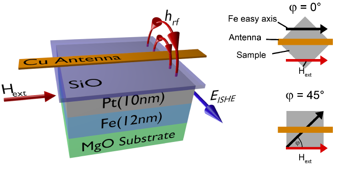
Fe (12 nm)/ Pt (10 nm) bilayers were grown on MgO (100) substrates (Fig. 1) by electron-beam evaporation in an ultrahigh vacuum (UHV) chamber with a base pressure of 3 10-11 mbar, at three different substrate temperatures: room temperature (), and . After the deposition of Fe/Pt, annealing for 30 minutes at the corresponding growth temperature was performed. Fe (12 nm)/Al (2.5 nm) reference films were also fabricated at the same experimental conditions as the Fe/Pt samples. The Al layer was deposited as a capping layer in order to form naturally an Al2O3 oxide protective layer.
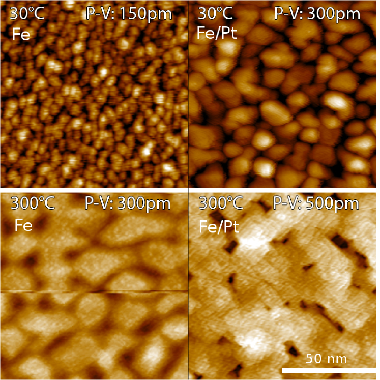
In Fig. 2 we present in-situ STM images for two samples grown at different temperatures: and . The left panels show the top surface of 12 nm Fe while the right panels show the surface after 10 nm of Pt growth. The Fe surfaces show a clear evolution with the growth temperature. The growth at results in the creation of small crystallites with a narrow size distribution that can be well fitted with a logarithmic - normal function, giving an average grain size of nm. As the growth temperature increases the average grain size become larger being nm for the sample and nm for . The size distribution is broader, and not any more well fitted by a log-norm function. Simultaneously, the mean square roughness Rrms increases from R = 0.13 nm for the sample to R = 0.17 nm and to R = 0.38 nm for the other two samples. While the grains themselves are essentially flat, the grain boundaries are rough leading to height differences between individual grains. Indeed, one can observe a dramatic change in the islands’ shape evolving from small spheres to almost square like crystallites for the samples. The grain size is strongly dependent on the ratio of the melting temperature of the deposited material (T) to the temperature of the substrate ( Tsubstrate): T / Tsubstrate. Hentzell et al. (1984); Karoutsos et al. (2007) For large values of the ratio one observes smaller grains with a narrower size distribution as for the RT sample, while for relatively smaller values of the ratio, a larger distribution of grain sizes with large grains as seen for the other two samples. The Pt evaporation on top of Fe seems to maintain the samples’ surface characteristics and the differences between the samples. Slightly larger grain sizes are observed. At the same time, the Rrms roughness is reduced for the grown at sample to R = 0.13 nm and for the sample to R = 0.23 nm. This is attributed to the better epitaxial relationship at the Fe/Pt interface as the X-ray diffraction (XRD) measurements reveal.
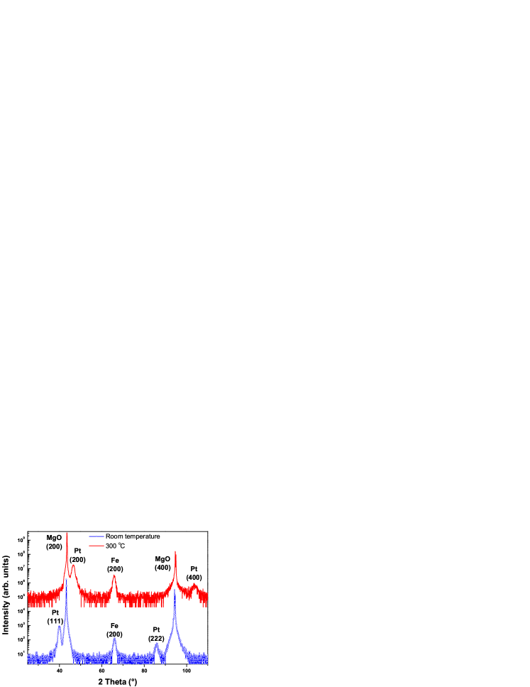
In Fig. 3, high-angle XRD patterns for two Fe/Pt samples are presented. Epitaxy of Fe on MgO (100) is observed for all growth temperatures. For the sample grown at RT the Pt on top of Fe exhibits a preferred orientation of (111) oriented grains. In contrast, diffraction peaks of Pt (200) and Pt (400) arise from the Pt top layer for the sample grown at (and at , not shown) parallel to the Fe (200) planes. The growth of the fcc Pt layer on bcc Fe along the [100] plane direction is of great interest. This kind of epitaxy can be correlated to the Bain epitaxial orientation Daniels et al. (1994) when the Pt cell is 45° rotated with respect to the Fe lattice. XRD pole figures (not shown here) reveal the complete coherency of Pt on Fe where four peaks of Pt (220) separated by 90°are rotated from the Fe (110) peaks by 45°. Furthermore, the pole figures confirm for all samples the 45°in plane epitaxial relation (Fe[100] MgO[110], Fe[110] MgO[010]) between the substrate and the Fe. The pronounced differences in the growth modes of the different Fe/Pt bilayers lead to different magnetic behaviour of the samples, different spin-pumping efficiencies and ISHE strengths, as it is shown in the next paragraph.
In plane magnetic measurements performed with the help of the magneto-optical Kerr effect revealed for all samples the presence of a four-fold in plane magnetic anisotropy together with a uniaxial magnetic anisotropy term (UMA). The presence of this UMA reduces the cubic symmetry, making the two in-plane Fe [110] directions inequivalent. Florczak and Dahlberg (1991) FMR and ISHE experiments were performed with the external magnetic field parallel to the film plane, in two different directions: °(Fe [100] easy axis) and °(Fe [110] hard axis) (see Fig. 1). In Fig. 4(a) the frequency dependence of the resonant field, measured in two different in plane directions and with two different setups (FMR, ISHE) are shown. The presented data refer to the sample grown at . The form of FMR spectra along the easy and hard axis point confirm the presence of four- and two-fold anisotropy Farle (1998); Zakeri et al. (2006). The peak positions of the FMR signal coincide with the ISHE data. The small discrepancy for low fields can be explained by imperfect azimuthal alignment. Small variations of the in-plane angle from the hard axis can cause large shifts of the FMR peak position. Zakeri et al. (2006)
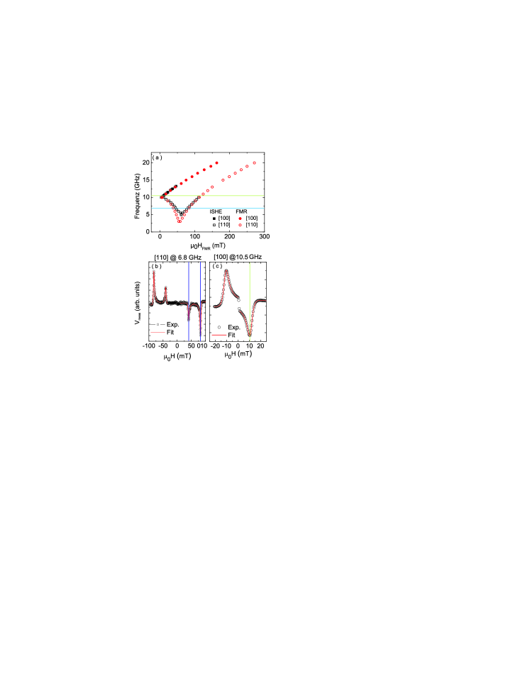
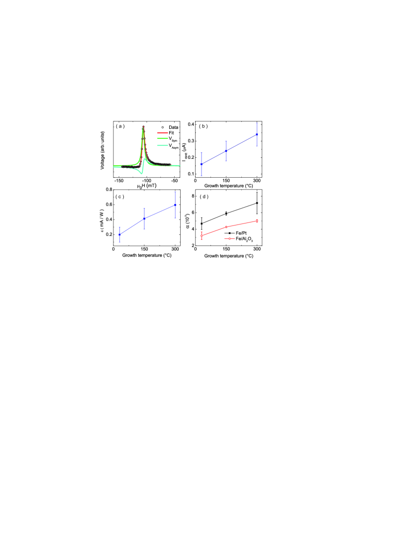
In FMR condition a spin current is effectively pumped from the Fe into the Pt layer. The magnetization dynamics is excited by the microwave magnetic field of a m Cu microstrip antenna, and the external magnetic field is swept. We measure the spin-pumping induced ISHE-voltage Jungfleisch et al. (2013a) that appears across the edges of the Pt layer perpendicular to the external magnetic field (see Fig. 1 induced electromotive force EISHE). In Fig. 4(b) the measured voltage (Vmeas) as a function of an external magnetic field applied in the [110] direction is presented, measured at 6.8 . With the field reversal a sign reversal in Vmeas signal is observed at the same absolute field values. The field values where the Vmeas peaks are measured agree with the FMR resonant positions at the measured frequency (denoted as horizontal lines in Fig. 4(a)) and confirm the spin pumping from Fe to Pt at the FMR frequencies. The reason for the appearance of two peaks is the alignment of the external field along the hard axis. Even though the external field H is increased, the intensity of the effective field Heff decreases as the direction of the magnetization is rotated from the easy axis to the hard axis. Once Heff is aligned in parallel to H, Heff increases. Thus, it is possible to meet the FMR condition at two different external field values. Similarly, Fig. 4(c) shows Vmeas with the external field H aligned along the [100] easy axis measured at a microwave frequency of 10.5 . Only one peak is observed along the easy direction as it is expected from the upper branch of the FMR spectrum of Fig. 4(a). In both Fig. 4(b) and (c) the amplitude and the shape of Vmeas reveal its dependence on the magnetic anisotropy of the films. However, as it has been previously discussed, Azevedo et al. (2011); Mosendz et al. (2010); Saitoh et al. (2006) Vmeas is the sum of three contributions: the spin pumping at the FMR frequency, the anisotropic magnetoresistance (AMR) effect at microwave fields, and the anomalous Hall effect (AHE). The possibility to distinguish between AMR and AHE contributions is given by the different dependencies of the effects with respect to the angle between the microwave antenna and the external magnetic field VAMR , VAHE . Juretschke (1960) Due to the strong anisotropy present in our samples, that renders the angular dependencies of VAMR and VAHE even more complicated, and due to limitations of our experimental setup to perform measurements with respect to another approach has been chosen to evaluated the data. This is based on the different signal forms of symmetric and antisymmetric components of Vmeas as it is shown in Fig. 5(a). The ISHE voltage (VISHE) at the FMR frequency obeys a Lorentz shape curve that can be decomposed into a symmetric and an antisymmetric part. Yoshino et al. (2011) The physical origin of the symmetric part is the ISHE itself together with contributions from AMR and AHE, while the antisymmetric part has only contributions from the AMR and AHE. The V curve can be considered as a function that is formed by symmetric and antisymmetric parts, where (H) and (H).
The red lines in Fig. 4(b) and (c) and in Fig. 5(a) superimposed on the experimental black open circles data points are a result of a fit containing both symmetric and antisymmetric parts. Fuhrmann (2013) In order to separate the symmetric ISHE contribution from the overlapping symmetric AMR and AHE signals we have fabricated reference Fe/Al2O3 samples. By measuring the reference samples, where no VISHE is expected, we could calculate the symmetric parameter ratio Aref by fitting the spectra of the Fe reference samples with the symmetric and antisymmetric parts, Eq. (1):
| (1) |
The antisymmetric contributions on Vmeas of the Fe/Pt samples can be fitted to the measured curve Fig. 4(b, c) and separated from the symmetric contribution. Assuming that the asymmetric part of the reference samples is the same as that of the Fe/Pt samples, we can estimate with the help of Eq. (1) by subtracting the symmetric part from the reference samples:
| (2) |
Fig. 5(b, c) summarizes data referring to the outer (higher magnetic field) peak of ISHE signal along the hard direction. In Fig. 5(b) the ISHE current, , increases linearly with deposition temperature. Alongside the material parameters, depends also on the absorbed microwave power at FMR frequency. To be able to compare the capability of different samples to convert an amount of absorbed energy via spin pumping into a DC current, we define the inverse spin Hall efficiency as: = IISHE / PAbs, where PAbs is the measured absorbed microwave power via the FMR mechanism. Fig. 5(c) shows that the efficiency rises with deposition temperature that provides smoother and larger grains at the interface and better quality of epitaxial samples.
Furthermore, with the help of the reference samples, we have calculated the characteristic parameter of SP, the effective spin mixing conductance g↑↓ Tserkovnyak et al. (2002b) for the Fe/Pt samples. g↑↓ is a quantifier of the efficiency of spin pumping since it describes the transfer of angular momentum at the interface to Pt. g↑↓ has been evaluated from FMR measurements from the linewidth of the FMR resonance that depends linearly on the microwave angular frequency. From the linear fit we have calculated the corresponding Gilbert damping parameter for both reference Fe/Al2O3 and Fe/Pt samples that we plot in Fig. 5(d). g↑↓ is then given by: Tserkovnyak et al. (2002b); Mosendz et al. (2010); Jungfleisch et al. (2013a)
| (3) |
where is the additional Gilbert damping constant due to the spin pumping. Eq. 3 gives g↑↓ values that are increasing with the growth temperature and the crystalline quality of the samples. In particular, g, g, and g for the samples grown at RT, , and respectively. The obtained values are close to the ones observed in Py/Pt Mosendz et al. (2010); Azevedo et al. (2011), g and one order of magnitude higher than in a single crystalline YIG surface in the YIG/Pt system Qiu et al. (2013) (reported values for YIG/Pt system though strongly vary in literature between m-2 and m-2).Jungfleisch et al. (2013a)
In summary, by controlling the epitaxial relationship and the interface morphology in Fe/Pt bilayers we were able to optimize the spin-pumping driven ISHE voltage. By increasing the growth temperature we have achieved epitaxy of Pt on Fe that led to an increase of ISHE current and ISHE efficiency. The spin-pumping induced ISHE voltage shows two distinct ISHE-voltage peaks along the hard magnetization axis revealing its strong dependence on the magnetic anisotropies. The manipulation of the magnon-to-charge current conversion with the crystal symmetry paves the way for further developments of the ISHE and its applications.
We thank A. Taroni for helpful discussions. Financial support by Deutsche Forschungsgemeinschaft CH 1037/1-1 is gratefully acknowledged.
References
- Saitoh et al. (2006) E. Saitoh, M. Ueda, H. Miyajima, and G. Tatara, Applied Physics Letters 88, 182509 (2006).
- Kajiwara et al. (2010) Y. Kajiwara, K. Harii, S. Takahashi, J. Ohe, K. Uchida, M. Mizuguchi, H. Umezawa, H. Kawai, K. Ando, K. Takanashi, S. Maekawa, and E. Saitoh, Nature 464, 262 (2010).
- Tserkovnyak et al. (2002a) Y. Tserkovnyak, A. Brataas, and G. Bauer, Physical Review Letters 88, 117601 (2002a).
- Hirsch (1999) J. E. Hirsch, Physical Review Letters 83, 1834 (1999).
- Czeschka et al. (2011) F. D. Czeschka, L. Dreher, M. S. Brandt, M. Weiler, M. Althammer, I. M. Imort, G. Reiss, A. Thomas, W. Schoch, W. Limmer, H. Huebl, R. Gross, and S. T. B. Goennenwein, Physical Review Letters 107, 046601 (2011).
- Nakayama et al. (2012) H. Nakayama, K. Ando, K. Harii, T. Yoshino, R. Takahashi, Y. Kajiwara, K. Uchida, Y. Fujikawa, and E. Saitoh, Phys. Rev. B 85, 144408 (2012).
- Mosendz et al. (2010) O. Mosendz, V. Vlaminck, J. E. Pearson, F. Y. Fradin, G. E. W. Bauer, S. D. Bader, and A. Hoffmann, Phys. Rev. B 82, 214403 (2010).
- Yoshino et al. (2011) T. Yoshino, K. Ando, and K. Harii, Applied Physics Letters 132503 (2011), 10.1063/1.3571556.
- Azevedo et al. (2011) A. Azevedo, L. H. Vilela-Leão, R. L. Rodríguez-Suárez, A. F. Lacerda Santos, and S. M. Rezende, Physical Review B 83, 144402 (2011).
- Jungfleisch et al. (2013a) M. B. Jungfleisch, V. Lauer, R. Neb, A. V. Chumak, and B. Hillebrands, Applied Physics Letters 103, 022411 (2013a).
- Ando et al. (2011) K. Ando, T. An, and E. Saitoh, Applied Physics Letters 99, 092510 (2011).
- Jungfleisch et al. (2013b) M. B. Jungfleisch, A. V. Chumak, A. Kehlberger, V. Lauer, D. H. Kim, M. C. Onbasli, C. A. Ross, M. Kläui, and B. Hillebrands, arXiv:1308.3787 (2013b).
- (13) V. Castel, N. Vlietstra, J. Ben Youssef, and B. J. van Wees, arXiv:1304.2190 .
- Castel et al. (2012) V. Castel, N. Vlietstra, J. Ben Youssef, and B. J. van Wees, Applied Physics Letters 101, 132414 (2012).
- Kurebayashi et al. (2011) H. Kurebayashi, O. Dzyapko, V. E. Demidov, D. Fang, A. J. Ferguson, and S. O. Demokritov, Applied Physics Letters 99, 162502 (2011).
- Sandweg et al. (2011) C. W. Sandweg, Y. Kajiwara, A. V. Chumak, A. A. Serga, V. I. Vasyuchka, M. B. Jungfleisch, E. Saitoh, and B. Hillebrands, Physical Review Letters 106, 216601 (2011).
- Chumak et al. (2012) A. V. Chumak, A. A. Serga, M. B. Jungfleisch, R. Neb, D. A. Bozhko, V. S. Tiberkevich, and B. Hillebrands, Applied Physics Letters 100, 082405 (2012).
- Jungfleisch et al. (2011) M. B. Jungfleisch, A. V. Chumak, V. I. Vasyuchka, A. A. Serga, B. Obry, H. Schultheiss, P. A. Beck, A. D. Karenowska, E. Saitoh, and B. Hillebrands, Applied Physics Letters 99, 2512 (2011).
- Qiu et al. (2013) Z. Qiu, K. Ando, and K. Uchida, arXiv:1302.7091v3 (2013).
- Hentzell et al. (1984) H. T. G. Hentzell, C. R. M. Grovenor, and D. A. Smith, Journal of Vacuum Science & Technology A: Vacuum, Surfaces, and Films 2, 218 (1984).
- Karoutsos et al. (2007) V. Karoutsos, P. Papasotiriou, P. Poulopoulos, V. Kapaklis, C. Politis, M. Angelakeris, T. Kehagias, N. K. Flevaris, and E. T. Papaioannou, Journal of Applied Physics 102, 043525 (2007).
- Daniels et al. (1994) B. Daniels, W. Nix, and B. Clemens, Thin Solid Films 253, 218 (1994).
- Florczak and Dahlberg (1991) J. M. Florczak and E. D. Dahlberg, Phys. Rev. B 44, 9338 (1991).
- Farle (1998) M. Farle, Reports on Progress in Physics 61, 755 (1998).
- Zakeri et al. (2006) K. Zakeri, T. Kebe, J. Lindner, and M. Farle, Journal of Magnetism and Magnetic Materials 299, L1 (2006).
- Juretschke (1960) H. J. Juretschke, Journal of Applied Physics 31, 1401 (1960).
- Fuhrmann (2013) P. Fuhrmann, Diplomarbeit, Technische Universität Kaiserslautern (2013).
- Tserkovnyak et al. (2002b) Y. Tserkovnyak, A. Brataas, and G. E. W. Bauer, Phys. Rev. B 66, 224403 (2002b).