Residual Amplitude Modulation in Interferometric Gravitational Wave Detectors
Abstract
The effects of residual amplitude modulation (RAM) in laser interferometers using heterodyne sensing can be substantial and difficult to mitigate. In this work, we analyze the effects of RAM on a complex laser interferometer used for gravitational wave detection. The RAM introduces unwanted offsets in the cavity length signals and thereby shifts the operating point of the optical cavities from the nominal point via feedback control. This shift causes variations in the sensing matrix, and leads to degradation in the performance of the precision noise subtraction scheme of the multiple-degree-of-freedom control system. In addition, such detuned optical cavities produce an opto-mechanical spring, which also varies the sensing matrix. We use our simulations to derive requirements on RAM for the Advanced LIGO detectors, and show that the RAM expected in Advanced LIGO will not limit its sensitivity.
pacs:
(040.0040) Detectors; (120.0120) Instrumentation, measurement, and metrology; (120.5060) Phase modulation; (140.0140) Lasers and laser optics.I Introduction
The direct detection of gravitational waves (GW) is a challenging but significant goal for fundamental physics and astronomy in the near future. There are several laser interferometric detector projects around the globe that aim to directly detect GWs from astrophysical sources, such as Advanced LIGO (aLIGO) PF:RPP2009 ; aLIGO , Advanced VIRGO 2006virgo , GEO-HF 2006GEO , and KAGRA KAGRA .
These interferometers are kilometer-scale Michelson interferometers with coupled Fabry-Perot cavities used to enhance the sensitivity to the spacetime strain induced by the GWs. The expected strains from astrophysical events should produce displacements of order m in these interferometers.
To measure such a small difference with a high signal-to-noise ratio, the lengths of the optical cavities in the interferometer must be controlled by precise positioning of all the constituent optics, ensuring that the optical response to the GW is linear.
The interferometric length signals are derived by heterodyne detection using a variant of the Pound-Drever-Hall (PDH) cavity locking technique Sigg:Readout : the laser light is phase-modulated at a certain frequency before being injected into the interferometer. A signal is then generated by the beat between the fields at different frequencies, such as the carrier field and modulation sidebands. In the aLIGO interferometer, phase modulation (PM) at two different frequencies is introduced to robustly extract the length signals for the multiple degrees of freedom (DoFs). In practice, the obtained heterodyne signals induce the cross-couplings between the GW DoF and auxiliary DoFs.
Due to imperfections (explained in later sections), the electro-optic modulator (EOM) used to impose PM sidebands on the optical field also introduces some residual amplitude modulation (RAM). This RAM is at the same frequencies as the PM and may therefore introduce spurious signals and offsets when the laser fields are sensed by photodetectors and demodulated to generate error signals. This may lead to changes in the frequency response to GWs (i.e. the calibration) and also to spurious couplings of laser noise to the GW readout channel.
In this paper, we present a model of how RAM affects the response of the GW interferometer and impacts its sensitivity. In Section II, we introduce RAM and describe its effect on the GW detectors. In Section III we give an overview of our simulation setup. Section IV presents the results: the predicted effect of RAM effect on aLIGO sensitivity. Simulation parameters and details of the sensing and control scheme used in our calculation can be found in Appendix A and B, respectively.
II RAM and advanced GW detectors
In this section, we first give an overview of the aLIGO optical configuration and its sensing and control scheme. Then, we introduce the issue of RAM and show how it may lead to problems with sensing and control.
| Definition | |
|---|---|
| DARM | |
| CARM | |
| MICH | |
| PRCL | |
| SRCL |
II.1 Optical configuration and sensing scheme of aLIGO
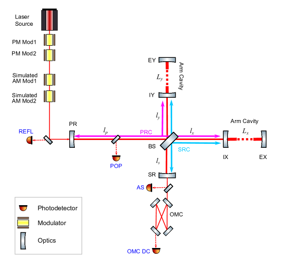
Fig. 1 shows the optical configuration of aLIGO. Each arm of the interferometer is a 4-km Fabry-Perot cavity that enhances the instrument’s response to GW signals. A power recycling cavity (PRC) enhances the effective incident laser power, and a signal recycling cavity (SRC) tunes the detection bandwidth. There are five DoFs to control: DARM, the differential motion of the two arm cavities (the GW channel); CARM, the common motion of the arm cavities; MICH, the difference between two short arms of the Michelson interferometer; PRCL, the PRC length, i.e., the average distance between the power-recycling mirror (PRM) and the two input test masses (ITMs, IX and IY in Fig. 1); SRCL, the SRC length, i.e., the average distance between the signal recycling mirror (SRM) to the two ITMs. The explicit definitions of these DoFs are summarized in Table 1.
To robustly extract length signals for the five DoFs, two sets of PM sidebands are used. Mirror motion induces phase modulation of the carrier and sideband laser fields which experience different resonant conditions in the interferometer due to the careful choice of modulation frequencies. Demodulated signals from photodetectors that sample fields extracted from the interferometer produce signals that contain information about the various DoFs.
II.2 Electro-optic modulator and RAM source
An electro-optic modulator (EOM) is a device used to modulate the phase of a laser field. An EOM consists of a Pockels cell—a crystal exhibiting a birefringence that depends linearly on the applied electric field—and a set of electrodes. The electrodes, attached on the top and bottom surfaces of the crystal, apply a voltage along one of the principal axes of the crystal. Fig. 2 shows the EOM crystal with voltage applied along axis, and the laser light polarized along the axis as an input. As the laser light passes through the crystal, the birefringence of the crystal changes due to the externally applied electric field and the laser light is phase-shifted. The phase shift induced by the electric field is written as where are the unperturbed refractive index in the direction, an electro-optic coefficient, the applied voltage, and the laser wavelength, respectively crystal .
During the phase modulation process, unwanted amplitude modulation is also imposed due to the following effects Whittaker ; WongHall ; etalon which are difficult to avoid in practice: (1) Axis mismatch between the incident polarization and the crystal orientation. When the input beam polarization axis does not align with one of the crystal axes and the axis of the applied electric field, the projections of the input field onto the crystal’s orthogonal axes obtain different phase shifts. For example, in Fig. 2, when the beam polarization is not along the direction, the laser field polarized in the direction obtains a phase shift, while the laser field polarized in the direction obtains a different phase shift. This leads to an effective rotation of the transmitted beam’s polarization, which, upon its subsequent interaction with polarizing optics, leads to AM. (2) Etalons in the crystal. Due to the finite reflectivities of the crystal faces, some light is circulated within the crystal. The multi-pass light field experiences a frequency-dependent phase shift and amplitude envelope due to this etalon effect.
In practice, the use of good anti-reflection (AR) coatings and wedged crystal faces makes (1) the dominant contribution to RAM.

Whatever the coupling, temperature fluctuations are usually the major driving force of RAM generation. Temperature drifts affect the mounting orientation of the crystal through the thermal expansion of the mounting material, and also lead directly to expansion of the crystal and modulation of its static birefringence. As such, a first approach to reducing RAM is simple temperature stabilization of the crystal and enclosure. More sophisticated techniques involve measuring the RAM optically and actively feeding back to either the modulation voltage WongHall or the crystal temperature Li .
II.3 Residual Amplitude Modulation
Residual amplitude modulation (RAM) is imposed at the same frequency as that of the intentional phase modulation. A laser field whose phase and amplitude are modulated at a frequency can be expressed as
| (1) |
where is the amplitude of the field, denotes the angular frequency of the carrier field, and are the modulation depths of the RAM and PM respectively, and is the relative phase between the RAM and PM terms. In order to evaluate the amount of the RAM relative to the PM, we define the RAM-to-PM ratio as
| (2) |
When PM is imposed at two different frequencies, the field with RAM can be written as,
| (3) |
where , , and are the arbitrary phases of the RAM and phase modulation terms.
Since they are at the same frequencies as the PM sidebands, the RAM sidebands introduce unwanted signal offsets when interferometer signals for a given DoF are extracted from the beat between the carrier field and a control sideband on a photodetector. Because the interferometer optics’ positions are controlled by servoing these error signals to zero, the offsets due to RAM can change their positions, affecting the interferometer response and degrading its sensitivity to GWs.
III Simulation
To evaluate the effect of RAM on the GW sensitivity, we used a frequency-domain simulation tool, Optickle optickle ; optickle2 . The aLIGO optical configuration (shown in Fig. 1) was modeled with parameters summarized in Appendix A.
There are three signal extraction ports in the interferometer: reflection (REFL) port, anti-symmetric (AS) port, and pick-off port (POP, pick off field from PRC). An input matrix (not shown) links the DoFs in the left column of Table 2 to the sensing signals in the middle column. We assigned these sensing ports so that each port has the maximum sensitivity to the assigned DoF. Similarly, an output matrix feeds the derived control signals to an optic position actuation path in the right column.
The gravitational wave channel (DARM) is detected at the output mode cleaner transmission port (OMC DC). This “DC readout” is a homodyne detection method, which requires the introduction of a small DARM offset to bring the AS port slightly off of a dark fringe (producing linear sensitivity to the DARM DoF). This scheme is proposed for the GW readout due to its better signal-to-noise ratio compared with the heterodyne readout DCreadout ; DCreadout2 ; DCreadout3 .
The actuation mapping on the right-hand side of Table 2 is chosen so as to maintain the orthogonality of the DoFs as best as possible; in practice, there is always some cross-coupling between DoFs. In the case of aLIGO, DARM is polluted most seriously by MICH and SRCL. To mitigate this effect, feedforward is applied from these DoFs to DARM—this feature is included in our simulation. See Appendix B for more information about the sensing and control scheme.
The frequency dependence from force to displacement of the suspended test masses is approximated using a transfer function where the response is flat up to 1 Hz peak and then drops as . This is an approximation of the transfer function of quadruple suspensions which suspend the main optics in aLIGO QUAD .
| DoF | Input | Output |
|---|---|---|
| DARM | OMC DC | EX – EY |
| CARM | REFL f1 | EX + EY |
| MICH | REFL f2 Q | BS –PR +SR |
| PRCL | REFL f2 I | PR |
| SRCL | POP f2 | SR |
IV Simulation results
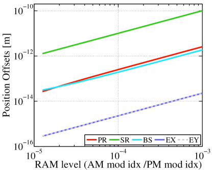
IV.1 Operating point offsets
The length offsets of each DoF due to RAM are shown in Fig. 3. These was calculated by the following iterative process: First, the error signal offset due to RAM is calculated. Then, the operating point of each DoF is changed so that the error signals are zero for the corresponding DoF. The error signal now has the different RAM offsets because the interferometer response is slightly changed by the length offsets. Therefore, a new length offset is added to make the new error signal zero. We iterate this process until the RAM offset and the operation point converge to below times the laser wavelength.
The largest effect of RAM is on the SRCL DoF, with smaller effects seen on PRCL and MICH. We can also see that a larger RAM level produces larger length offsets. CARM and DARM (EX and EY in Fig. 3) are less sensitive to RAM because the frequency discriminants of the corresponding error signals are enhanced by the Fabry-Perot arm cavities. In addition, the DARM DoF is read out using homodyne detection (i.e., there are no RF sidebands) and is therefore only sensitive to RAM via the cross-coupling effects described above.
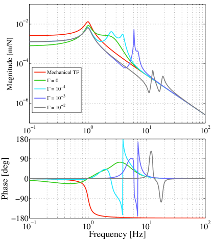
IV.2 Effects on opto-mechanical response
The opto-mechanical response is altered when RAM is present. Fig. 4 shows this transfer function from force to displacement of test masses, with a PM-to-RAM ratio ranging from 0 to . Opto-mechanical peaks appear even even when RAM is absent, , because of the slight DARM offset for DC readout (3 pm is used here). With or more, the opt-mechanical peaks become sharper due to the length offsets shown in the previous subsection. These small offsets—particularly that to SRCL—result in detuned operation of the signal recycling cavity (0.078 degrees for ), which gives rise to the opto-mechanical spring. Such resonances may add instability to the control loop and should be avoided.
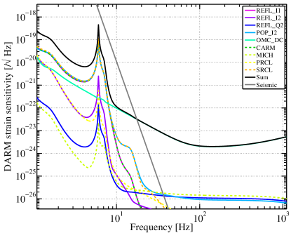
IV.3 Strain sensitivity and loop noise
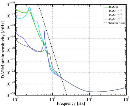
Due to this change in optical response, the resulting strain sensitivity is altered as shown in Fig. 5. There is no significant difference with , the level measured in the EOM in use at the LIGO Livingston Observatory. Even with larger Gamma, the quantum noise is little affected above 10 Hz.
Note that quantum noise contributions from auxiliary DoFs are included in Fig. 5, in addition to the quantum noise intrinsic to DARM. In Fig. 6, we see the breakdown of the DARM sensitivity for the case of . The noise intrinsic to the DARM loop is shown in the light green trace (“OMC_DC”), and all other traces are cross-couplings. Below around 12 Hz, the total noise (i.e., the red trace in Fig. 6) is dominated by contributions from other DoFs. This is the reason for the seeming enhancement in DARM sensitivity with increasing RAM; the contribution from cross-coupling is indeed suppressed due to the modified response, but the noise intrinsic to the DARM loop experiences no such reduction. Therefore, the ideal quantum-noise-limited GW sensitivity is not improved by the introduction of RAM. To the contrary, it is diminished for higher levels of RAM, and it is not effected appreciably by the levels considered here. In any case, the sensitivity of aLIGO to GWs is predicted to be completely dominated by seismic noise at these low frequencies, as shown by the gray trace in Fig. 5.
Appendix A Simulation parameters
The optical parameters are chosen to model the aLIGO Livingston interferometer, as listed in Table 3 and found in aLIGOparam ; aLIGOparam2 . The servo filters are chosen to have a unity gain frequency (UGF) of 200 Hz for DARM, 50 kHz for CARM, and 20 Hz for PRCL, 15 Hz for MICH and 10 Hz for SRCL.
| Arm lengths | 3994.5 m |
|---|---|
| Arm cavity FWHM / FSR | 84.2344 Hz / 37.526 kHz |
| PRC length | 57.6562 m |
| PRC FWHM / FSR | 13.190 kHz / 2.5998 MHz |
| SRC length | 56.0082 m |
| SRC FWHM / FSR | 179.18 kHz / 3.7526 MHz |
| Schnupp Asymmetry | 8 cm |
| Short Michelson arm length | 5.3428 m (average) |
| PRM transmissivity | 0.03 |
| SRM transmissivity | 0.35 |
| ITM transmissivity | 0.14 |
| ETM transmissivity | 5 ppm |
| Input laser power | 135 W or 25 W |
| Optics loss (per mirror) | 30 ppm |
| OMC transmissivity | 0.99 |
| PM1 frequency | 9.099471 MHz |
| PM2 frequency | 45.497355 MHz |
| PM1 modulation index | 0.1 |
| PM2 modulation index | 0.1 |
Appendix B Sensing Scheme
In this section, we describe in detail the sensing signals and the control scheme used in our simulation, including a brief description of the multiple-DoF control method.
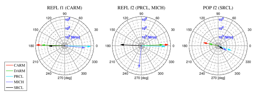
B.1 Sensing and Control
Fig. 7 is the radar plot representing the signals in each sensors. The five DoF signals in each sensor (i.e., in each radar) are shown as arrows. The arrow length is the signal strength in W/m in logarithmic scale and the angles are the optimum demodulation phases in degrees. Because the DC readout signals (OMC DC sensor) for DARM is a DC signal and does not have demodulation phase, it is not listed in the radar plot.
The desired signal at each sensor is obtained by demodulating at the optimum demodulation phase for the targeted DoF. Undesired signals mix into the obtained signal with a ratio determined by the relative phase separation from the desired signal. The sensors are chosen to, as much as possible, separate the various length signals from one another to maximize sensitivity to the desired DoF and minimize cross-coupling from other DoFs. The signals shown in 7 are calculated at 20 Hz, with an input power of 25 W, and a differential arm offset of 3 pm.
Table 4 shows the conventional sensing matrix of our model. This matrix is often used to express the signal sensitivity to the different DoFs, at each detection port, at a certain frequency sensmatrix . The first column of a sensing matrix shows the sensors, which is a choice of the detection port, demodulation frequency, and demodulation phase (I- or Q-phase), and the rows of a sensing matrix show the gains of the optical response for each DoF. The diagonal elements of the matrix correspond to the sensitivity of the given sensor to the DoF to be controlled by it, and the off-diagonal elements show the contributions from the other DoFs. One sensor is fed back to one DoF for the control, therefore, we have five sensors to control the five DoFs.
For example, in our model, OMC DC is chosen for the DARM control, having the maximum sensitivity to DARM, with a some contribution from PRCL, MICH and SRCL.
| Sensor | Phase | CARM | DARM | PRCL | MICH | SRCL |
|---|---|---|---|---|---|---|
| REFL I1 | 178∘ | |||||
| OMC DC | N/A | |||||
| REFL I2 | -2∘ | |||||
| REFL I2 | -96∘ | |||||
| POP I2 | 34∘ |
B.2 Signal Mixture
The fact that each sensor is sensitive to all DoFs (in the other words, the sensing matrix is not completely diagonal), leads to difficulties with interferometer sensing and control. When the sensor signal at a given port is fed back to its target interferometer DoF, some non-target-DoF signal is also fed back to that DoF due to these cross-couplings.
The DARM signal at the anti-symmetric ports (AS and OMC DC) can not be cleanly separated from that of MICH because—from the point of view of the dark port—differential arm or Michelson motion are essentially equivalent (the gain at the AS port is much larger for DARM than for MICH because DARM is enhanced by the arm cavities). Therefore, there is always a MICH signal mixing into the DARM feedback signal, even if the displacement in the MICH DoF is suppressed to the shot-noise level: Because the optical gain of MICH is smaller than that of DARM, which is enhanced by the resonant arm cavity, the shot noise limited sensitivity of MICH is worse than DARM. As a consequence, the cross-coupled MICH signal increases the effective shot noise of the DARM sensor.
As for second-order effects, the SRCL, PRCL and CARM signals are also mixed into DARM through the MICH mixture path somiya . The SRCL, PRCL, and CARM sensors have higher shot noise level than that of DARM, because they are (in general) extracted at REFL or POP, both of which have higher light power than the DARM port at the dark fringe. Also, SRCL is almost always degenerate with the other DoFs and difficult to extract independently because the finesse of SRC is much lower than those of the other DoFs. Therefore, SRCL has a relatively low signal-to-noise ratio, and the shot noise at the SRCL sensor appears in the displacement sensitivity of DARM by way of the MICH mixture path.
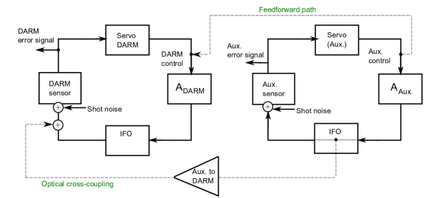
Fig. 8 shows a simplified diagram of the control loops. For example, shot noise is added at each sensor into its respective loop, and coupled into the DARM error signal. Quantum noise shown in solid traces in Fig. 6 is by the following coupling process; The shot noise in each sensor propagates to each error signal as
| (4) |
where is an identity matrix, is the open-loop transfer function (in the frequency domain) of the five DoF loop including the servo filter shapes, , actuator matrix, , input matrix, , output matrix, and the optical response as a matrix, . Input and output matrices are the matrices to change either from the sensor basis to the DoF basis, or, from the DoF basis to the actuator basis, respectively (matrix form of Table 2, in the other words). Here, and are matrices. And and are diagonal matrices. Note that the radiation pressure is also summed as the quantum noises in Fig. 6 in the both coupling processes. The solid traces in Fig. 6 is the DARM element of Eq. 4.
On the other hand, control noises, the dashed traces in Fig. 6, are expressed as
| (5) |
where is the control signal vector for the five DoFs. Here, for the control signal, the shot noise and radiation pressure noises are considered in .
The calibrated displacement sensitivity is written as
| (6) |
As neither nor is diagonal, shot noise at every sensor pollutes the DARM sensitivity. The optical cross-coupling path is shown as gray dashed line on the bottom left in Fig. 8.
B.3 Calibration
To calibrate the DARM displacement, [m/] (the DARM element in Eq. 6), into strain sensitivity, [1/], down to low frequencies, we have to take into account the suspension transfer function of the test masses (or opto-mechanical transfer function when optical spring effect gives rise). Treating the gravitational wave as tidal force, we have
| (7) |
where is the arm length, is the angular frequency of the signal, is the (opto-) mechanical transfer function. Note that Eq. 7 is valid where the gravitational wave length is larger than . In our case of km, this calibration method is valid from DC to 75 kHz Saulson .
B.4 Feedforward
A feedforward technique is used to partially suppress the coupling from the auxiliary DoF control signals into the DARM control signal. As evidenced by the off-diagonal elements of the sensing matrix, there are cross couplings from all the auxiliary DoFs into DARM. In particular the SRCL signal cannot be extracted independently, and it creates a large second-order coupling. In our simulation, the couplings from SRCL to DARM, and from MICH to DARM are subtracted from the control signal by the feedforward path (dashed gray line in Fig. 8) so as to subtract the undesired contributions from SRCL and MICH above 20 Hz. The suppression ratios due to the feedforward at 20 Hz are 0.4 % for MICH and 4 % SRCL control noise.
This feedforward method was used in the first-generation GW detector Initial LIGO and is planned to be implemented in aLIGO, as well.
References
- (1) B. P. Abbott, R. Abbott, R. Adhikari, P. Ajith, B. Allen, G. Allen, R. S. Amin, S. B. Anderson, W. G. Anderson, M. A. Arain, M. Araya, H. Armandula, P. Armor, Y. Aso, S. Aston, P. Aufmuth, C. Aulbert, S. Babak, P. Baker, S. Ballmer, C. Barker, D. Barker, B. Barr, P. Barriga, L. Barsotti, M. A. Barton, I. Bartos, R. Bassiri, M. Bastarrika, B. Behnke, M. Benacquista, J. Betzwieser, P. T. Beyersdorf, I. A. Bilenko, G. Billingsley, R. Biswas, E. Black, J. K. Blackburn, L. Blackburn, D. Blair, B. Bland, T. P. Bodiya, L. Bogue, R. Bork, V. Boschi, S. Bose, P. R. Brady, V. B. Braginsky, J. E. Brau, D. O. Bridges, M. Brinkmann, A. F. Brooks, D. A. Brown, A. Brummit, G. Brunet, A. Bullington, A. Buonanno, O. Burmeister, R. L. Byer, L. Cadonati, J. B. Camp, J. Cannizzo, K. C. Cannon, J. Cao, L. Cardenas, S. Caride, G. Castaldi, S. Caudill, M. Cavaglià, C. Cepeda, T. Chalermsongsak, E. Chalkley, P. Charlton, S. Chatterji, S. Chelkowski, Y. Chen, N. Christensen, C. T. Y. Chung, D. Clark, J. Clark, J. H. Clayton, T. Cokelaer, C. N. Colacino, R. Conte, D. Cook, T. R. C. Corbitt, N. Cornish, D. Coward, D. C. Coyne, J. D. E. Creighton, T. D. Creighton, A. M. Cruise, R. M. Culter, A. Cumming, L. Cunningham, S. L. Danilishin, K. Danzmann, B. Daudert, G. Davies, E. J. Daw, D. DeBra, J. Degallaix, V. Dergachev, S. Desai, R. DeSalvo, S. Dhurandhar, M. Díaz, A. Dietz, F. Donovan, K. L. Dooley, E. E. Doomes, R. W. P. Drever, J. Dueck, I. Duke, J. C. Dumas, J. G. Dwyer, C. Echols, M. Edgar, A. Effler, P. Ehrens, E. Espinoza, T. Etzel, M. Evans, T. Evans, S. Fairhurst, Y. Faltas, Y. Fan, D. Fazi, H. Fehrmenn, L. S. Finn, K. Flasch, S. Foley, C. Forrest, N. Fotopoulos, A. Franzen, M. Frede, M. Frei, Z. Frei, A. Freise, R. Frey, T. Fricke, P. Fritschel, V. V. Frolov, M. Fyffe, V. Galdi, J. A. Garofoli, I. Gholami, J. A. Giaime, S. Giampanis, K. D. Giardina, K. Goda, E. Goetz, L. M. Goggin, G. González, M. L. Gorodetsky, S. Goßler, R. Gouaty, A. Grant, S. Gras, C. Gray, M. Gray, R. J. S. Greenhalgh, A. M. Gretarsson, F. Grimaldi, R. Grosso, H. Grote, S. Grunewald, M. Guenther, E. K. Gustafson, R. Gustafson, B. Hage, J. M. Hallam, D. Hammer, G. D. Hammond, C. Hanna, J. Hanson, J. Harms, G. M. Harry, I. W. Harry, E. D. Harstad, K. Haughian, K. Hayama, J. Heefner, I. S. Heng, A. Heptonstall, M. Hewitson, S. Hild, E. Hirose, D. Hoak, K. A. Hodge, K. Holt, D. J. Hosken, J. Hough, D. Hoyland, B. Hughey, S. H. Huttner, D. R. Ingram, T. Isogai, M. Ito, A. Ivanov, B. Johnson, W. W. Johnson, D. I. Jones, G. Jones, R. Jones, L. Ju, P. Kalmus, V. Kalogera, S. Kandhasamy, J. Kanner, D. Kasprzyk, E. Katsavounidis, K. Kawabe, S. Kawamura, F. Kawazoe, W. Kells, D. G. Keppel, A. Khalaidovski, F. Y. Khalili, R. Khan, E. Khazanov, P. King, J. S. Kissel, S. Klimenko, K. Kokeyama, V. Kondrashov, R. Kopparapu, S. Koranda, D. Kozak, B. Krishnan, R. Kumar, P. Kwee, P. K. Lam, M. Landry, B. Lantz, A. Lazzarini, H. Lei, M. Lei, N. Leindecker, I. Leonor, C. Li, H. Lin, P. E. Lindquist, T. B. Littenberg, N. A. Lockerbie, D. Lodhia, M. Longo, M. Lormand, P. Lu, M. Lubinski, A. Lucianetti, H. Lück, B. Machenschalk, M. MacInnis, M. Mageswaran, K. Mailand, I. Mandel, V. Mandic, S. Márka, Z. Márka, A. Markosyan, J. Markowitz, E. Maros, I. W. Martin, R. M. Martin, J. N. Marx, K. Mason, F. Matichard, L. Matone, R. A. Matzner, N. Mavalvala, R. McCarthy, D. E. McClelland, S. C. McGuire, M. McHugh, G. McIntyre, D. J. A. McKechan, K. McKenzie, M. Mehmet, A. Melatos, A. C. Melissinos, D. F. Menéndez, G. Mendell, R. A. Mercer, S. Meshkov, C. Messenger, M. S. Meyer, J. Miller, J. Minelli, Y. Mino, V. P. Mitrofanov, G. Mitselmakher, R. Mittleman, O. Miyakawa, B. Moe, S. D. Mohanty, S. R. P. Mohapatra, G. Moreno, T. Morioka, K. Mors, K. Mossavi, C. MowLowry, G. Mueller, H. Müller-Ebhardt, D. Muhammad, S. Mukherjee, H. Mukhopadhyay, A. Mullavey, J. Munch, P. G. Murray, E. Myers, J. Myers, T. Nash, J. Nelson, G. Newton, A. Nishizawa, K. Numata, J. O’Dell, B. O’Reilly, R. O’Shaughnessy, E. Ochsner, G. H. Ogin, D. J. Ottaway, R. S. Ottens, H. Overmier, B. J. Owen, Y. Pan, C. Pankow, M. A. Papa, V. Parameshwaraiah, P. Patel, M. Pedraza, S. Penn, A. Perraca, V. Pierro, I. M. Pinto, M. Pitkin, H. J. Pletsch, M. V. Plissi, F. Postiglione, M. Principe, R. Prix, L. Prokhorov, O. Punken, V. Quetschke, F. J. Raab, D. S. Rabeling, H. Radkins, P. Raffai, Z. Raics, N. Rainer, M. Rakhmanov, V. Raymond, C. M. Reed, T. Reed, H. Rehbein, S. Reid, D. H. Reitze, R. Riesen, K. Riles, B. Rivera, P. Roberts, N. A. Robertson, C. Robinson, E. L. Robinson, S. Roddy, C. Röver, J. Rollins, J. D. Romano, J. H. Romie, S. Rowan, A. Rüdiger, P. Russell, K. Ryan, S. Sakata, Sancho de la Jordana, V. Sandberg, V. Sannibale, L. Santamaría, S. Saraf, P. Sarin, B. S. Sathyaprakash, S. Sato, M. Satterthwaite, P. R. Saulson, R. Savage, P. Savov, M. Scanlan, R. Schilling, R. Schnabel, R. Schofield, B. Schulz, B. F. Schutz, P. Schwinberg, J. Scott, S. M. Scott, A. C. Sea. LIGO: the laser interferometer Gravitational-Wave observatory. Reports on Progress in Physics, 72(7):076901+, July 2009.
- (2) Gregory M Harry and the LIGO Scientific Collaboration. Advanced LIGO: the next generation of gravitational wave detectors. Classical and Quantum Gravity, 27(8):084006, 2010.
- (3) F Acernese, P Amico, M Alshourbagy, F Antonucci, S Aoudia, S Avino, D Babusci, G Ballardin, F Barone, L Barsotti, M Barsuglia, F Beauville, S Bigotta, S Birindelli, M A Bizouard, C Boccara, F Bondu, L Bosi, C Bradaschia, S Braccini, A Brillet, V Brisson, L Brocco, D Buskulic, E Calloni, E Campagna, F Cavalier, R Cavalieri, G Cella, E Cesarini, E Chassande-Mottin, C Corda, F Cottone, A-C Clapson, F Cleva, J-P Coulon, E Cuoco, A Dari, V Dattilo, M Davier, R De Rosa, L Di Fiore, A Di Virgilio, B Dujardin, A Eleuteri, D Enard, I Ferrante, F Fidecaro, I Fiori, R Flaminio, J-D Fournier, O Francois, S Frasca, F Frasconi, A Freise, L Gammaitoni, F Garufi, A Gennai, A Giazotto, G Giordano, L Giordano, R Gouaty, D Grosjean, G Guidi, S Hebri, H Heitmann, P Hello, L Holloway, S Karkar, S Kreckelbergh, P La Penna, M Laval, N Leroy, N Letendre, M Lorenzini, V Loriette, M Loupias, G Losurdo, J-M Mackowski, E Majorana, C N Man, M Mantovani, F Marchesoni, F Marion, J Marque, F Martelli, A Masserot, M Mazzoni, L Milano, C Moins, J Moreau, N Morgado, B Mours, A Pai, C Palomba, F Paoletti, S Pardi, A Pasqualetti, R Passaquieti, D Passuello, B Perniola, F Piergiovanni, L Pinard, R Poggiani, M Punturo, P Puppo, K Qipiani, P Rapagnani, V Reita, A Remillieux, F Ricci, I Ricciardi, P Ruggi, G Russo, S Solimeno, A Spallicci, R Stanga, R Taddei, M Tonelli, A Toncelli, E Tournefier, F Travasso, G Vajente, D Verkindt, F Vetrano, A Viceré, J-Y Vinet, H Vocca, M Yvert, and Z Zhang. The Virgo status. Classical and Quantum Gravity, 23(19):S635, 2006.
- (4) H Lück, M Hewitson, P Ajith, B Allen, P Aufmuth, C Aulbert, S Babak, R Balasubramanian, B W Barr, S Berukoff, A Bunkowski, G Cagnoli, C A Cantley, M M Casey, S Chelkowski, Y Chen, D Churches, T Cokelaer, C N Colacino, D R M Crooks, C Cutler, K Danzmann, R J Dupuis, E Elliffe, C Fallnich, A Franzen, A Freise, I Gholami, S Goßler, A Grant, H Grote, S Grunewald, J Harms, B Hage, G Heinzel, I S Heng, A Hepstonstall, M Heurs, S Hild, J Hough, Y Itoh, G Jones, R Jones, S H Huttner, K Kötter, B Krishnan, P Kwee, M Luna, B Machenschalk, M Malec, R A Mercer, T Meier, C Messenger, S Mohanty, K Mossavi, S Mukherjee, P Murray, G P Newton, M A Papa, M Perreur-Lloyd, M Pitkin, M V Plissi, R Prix, V Quetschke, V Re, T Regimbau, H Rehbein, S Reid, L Ribichini, D I Robertson, N A Robertson, C Robinson, J D Romano, S Rowan, A Rüdiger, B S Sathyaprakash, R Schilling, R Schnabel, B F Schutz, F Seifert, A M Sintes, J R Smith, P H Sneddon, K A Strain, I Taylor, R Taylor, A Thüring, C Ungarelli, H Vahlbruch, A Vecchio, J Veitch, H Ward, U Weiland, H Welling, L Wen, P Williams, B Willke, W Winkler, G Woan, and R Zhu. Status of the GEO600 detector. Classical and Quantum Gravity, 23(8):S71, 2006.
- (5) Kentaro Somiya. Detector configuration of KAGRA–the Japanese cryogenic gravitational-wave detector. Classical and Quantum Gravity, 29(12):124007, 2012.
- (6) Peter Fritschel, Rolf Bork, Gabriela González, Nergis Mavalvala, Dale Ouimette, Haisheng Rong, Daniel Sigg, and Michael Zucker. Readout and control of a power-recycled interferometric gravitational-wave antenna. Appl. Opt., 40(28):4988–4998, Oct 2001.
- (7) M. Bass et al. Handbook of Optics, Third Edition Volume II: Design, Fabrication and Testing, Sources and Detectors, Radiometry and Photometry. McGraw-Hill Professional, 2009.
- (8) Edward A. Whittaker, Manfred Gehrtz, and Gary C. Bjorklund. Residual amplitude modulation in laser electro-optic phase modulation. J. Opt. Soc. Am. B, 2(8):1320–1326, Aug 1985.
- (9) N. C. Wong and J. L. Hall. Servo control of amplitude modulation in frequency-modulation spectroscopy: demonstration of shot-noise-limited detection. J. Opt. Soc. Am. B, 2(9):1527–1533, Sep 1985.
- (10) Newport Corp. High-Frequency Electro-Optic Phase Modulators – Model Series 44xx and 485xx User’s Manual.
- (11) Liufeng Li, Fang Liu, Chun Wang, and Lisheng Chen. Measurement and control of residual amplitude modulation in optical phase modulation. Review of Scientific Instruments, 83(4):043111, 2012.
- (12) M. Evans. Optickle. http://www.ligo.mit.edu/~mevans/resources.html.
- (13) Matthew Evans. Optickle. Technical Report T070260-v1, Massachusetts Institute of Technology, 2007.
- (14) R. L. Ward. Length Sensing and Control of a Prototype Advanced Interferometric Gravitational Wave Detector. PhD thesis, California Institute of Technology, 2010.
- (15) T. T. Fricke. Homodyne Detection for Laser-Interferometric Gravitational Wave Detectors. PhD thesis, Louisiana State University, 2011.
- (16) Alessandra Buonanno, Yanbei Chen, and Nergis Mavalvala. Quantum noise in laser-interferometer gravitational-wave detectors with a heterodyne readout scheme. Phys. Rev. D, 67:122005, Jun 2003.
- (17) S M Aston, M A Barton, A S Bell, N Beveridge, B Bland, A J Brummitt, G Cagnoli, C A Cantley, L Carbone, A V Cumming, L Cunningham, R M Cutler, R J S Greenhalgh, G D Hammond, K Haughian, T M Hayler, A Heptonstall, J Heefner, D Hoyland, J Hough, R Jones, J S Kissel, R Kumar, N A Lockerbie, D Lodhia, I W Martin, P G Murray, J O’Dell, M V Plissi, S Reid, J Romie, N A Robertson, S Rowan, B Shapiro, C C Speake, K A Strain, K V Tokmakov, C Torrie, A A van Veggel, A Vecchio, and I Wilmut. Update on quadruple suspension design for Advanced LIGO. Classical and Quantum Gravity, 29(23):235004, 2012.
- (18) R. Abbott, R. X. Adhikari, S. Ballmer, L. Barsotti, M. Evans, P. Fritschel, V. Frolov, G. Mueller, B. Slagmolen, and S. Waldman. AdvLIGO interferometer sensing and control conceptual design. Technical Report LIGO-T070247, 2007.
- (19) M. Evans L. Barsotti and P. Fritschel. Advanced LIGO ISC design study for low power operation. Technical Report T1200128-v4, 2012.
- (20) Shuichi Sato, Seiji Kawamura, Keiko Kokeyama, Fumiko Kawazoe, and Kentaro Somiya. Diagonalization of the length sensing matrix of a dual recycled laser interferometer gravitational wave antenna. Phys. Rev. D, 75:082004, Apr 2007.
- (21) Kentaro Somiya and Osamu Miyakawa. Shot-noise-limited control-loop noise in an interferometer with multiple degrees of freedom. Appl. Opt., 49(23):4335–4342, Aug 2010.
- (22) Peter R. Saulson. Fundamentals of Interferometric Gravitational Wave Detectors. World Scientific Pub Co Inc, 1994.