Project PROMETHEUS:
Design and Construction of a Radio Frequency Quadrupole at TAEK
Abstract
The PROMETHEUS Project is ongoing for the design and development of a 4-vane radio frequency quadrupole (RFQ) together with its ion source, a low energy beam transport (LEBT) line and diagnostics section. The main goal of the project is to achieve the acceleration of the low energy ions up to 1.5 MeV by an RFQ (352 MHz) shorter than 2 meter. A plasma ion source is being developed to produce a 20 keV, 1 mA beam. Simulation results for ion source, transmission and beam dynamics are presented together with analytical studies performed with newly developed RFQ design code DEMIRCI. Simulation results shows that a beam transmission 99% could be achieved at 1.7 m downstream reaching an energy of 1.5 MeV. As the first phase an Aluminum RFQ prototype, the so-called cold model, will be built for low power RF characterization. In this contribution the status of the project, design considerations, simulation results, the various diagnostics techniques and RFQ manufacturing issues are discussed.
1 Introduction
An energetic proton beam is indeed a very useful tool: It’s usage ranges from basic scientific research (like in the case of the LHC) to a medical application (such as Hadron Therapy) or from production of secondary beamlines to simply being a tool for educational and test purposes. The common properties of all proton (linear) beamlines is to start with an ion source, followed by a Low Energy Beam Transport (LEBT), and an accelerating structure effective at low beta (). The structure of choice for the accelerating structure is a Radio Frequency Quadrupole (RFQ) since 1980s. The PROMETHEUS project, at the Turkish Atomic Energy Authority’s (TAEK) Saraykoy Nuclear Research and Training Center (SANAEM), aims to gain the necessary knowledge and experience to construct such a proton beam. A Proof of Principle (PoP) accelerator with modest requirements of achieving at least 1.5 MeV proton energy, with an average beam current of at least 1 mA is under development. PoP project also have the challenging goal of having the design and construction of the entire machine in Turkey, from its ion source up to last diagnostic station, including its RF power supply and to complete it in three years. There are also two secondary goals of this project: 1) Training accelerator physicists and RF engineers on the job; 2) To encourage local industry in accelerator component construction.
2 Beamline Design
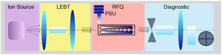
The beamline design originates from previous setups and past experience of SANAEM. It consists of an ion source, a LEBT, a RFQ and a beam dump with diagnostic stations inserted at the appropriate places. A schematic view of the beamline can be seen in Fig. 1.
2.1 Ion Source
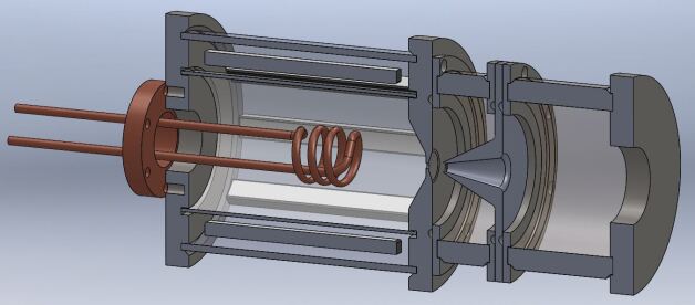
The ion source, consisting of two parts (plasma generator and extraction system) is being redesigned to match the required input parameters of the main accelerator structure, i.e. the RFQ. It should give as much current as possible at a low energy to keep the RFQ length as short as possible. Therefore, the main parameters of the ion source are: 20 keV output energy, at least 1mA of average beam current and a total normalized transverse emittance smaller than 1.5 .mm.mrad. The actual design is realized with IBSimu[1] and SimIon[2] software packages. Although the ion plasma can be generated by various methods, this work focuses on two options: By heating a filament with DC to provoke thermionic emission and alternatively by using an RF antenna. The plasma confinement system is achieved with 8 rod permanent multicusp magnets with a field of 4000 Gauss each. The requirement of using ions simplifies the extraction system to only 3 electrodes. The whole system is designed to be water-cooled housed in a Plexiglas vessel. The 3D representation of the ion source currently under construction is shown in Fig 2.
2.2 LEBT
The LEBT is used to transport the beam exiting the ion source with a minimum loss of particles up to the input of the RFQ and also to match its input parameters. The desired beam parameters will be achieved by the use of two solenoid magnets of length 15 cm each. The LEBT design is obtained with TRAVEL [3] software library and the solenoids themselves by the use of SUPERFISH [4]. The magnetic fields of the two solenoids have been calculated as 2830 Gauss at cm and 2480 Gauss at cm.
2.3 RFQ
The decision on the ion type, namely the selection of , also dictates the type of the RFQ as 4-vane type. Considering the local manufacturing capabilities and constraints, the inter-vane voltage was selected to be 60 kV, constant throughout the RFQ. Similar arguments lead to 1.5 as the Kilpatrick value. The decision on the RF operation frequency was not based on the readily available material but on the collaboration possibilities with CERN. Choice of 352.21 MHz operations frequency is compatible with the 4-vane decision and also results in a compact size RFQ cell that is compatible with the local CNC (Computer Numerical Control) capabilities. The actual design is made by the use of two computer programs (LIDOS [5] and DEMIRCI [6] discussed below.), cross-checking each other.
The SANAEM RFQ has been designed using LIDOS, one of the two commercially available computer programs. The main design parameters can be found in Table 1. The preliminary result from ”LIDOS.Advisor”, satisfies the initial design requirements, namely obtaining 1.5 MeV energy in less than 2 meters with two sections less than 90 cm each. This software package provides a total solution including the final vane design files that can be fed directly to the CNC machines. However some difficulties in running it in batch mode and in obtaining some design parameters as a text file lead us to develop a similar computer program, DEMIRCI, with local resources.
| Parameter | Value | Unit |
| 20 | keV | |
| 1.5 | MeV | |
| 352.21 | MHz | |
| I | 1 | mA |
| 1 | .mm.mrad | |
| 60 | kV | |
| KP | 1.5 | - |
| 2.799 | mm | |
| 2.5 | mm |
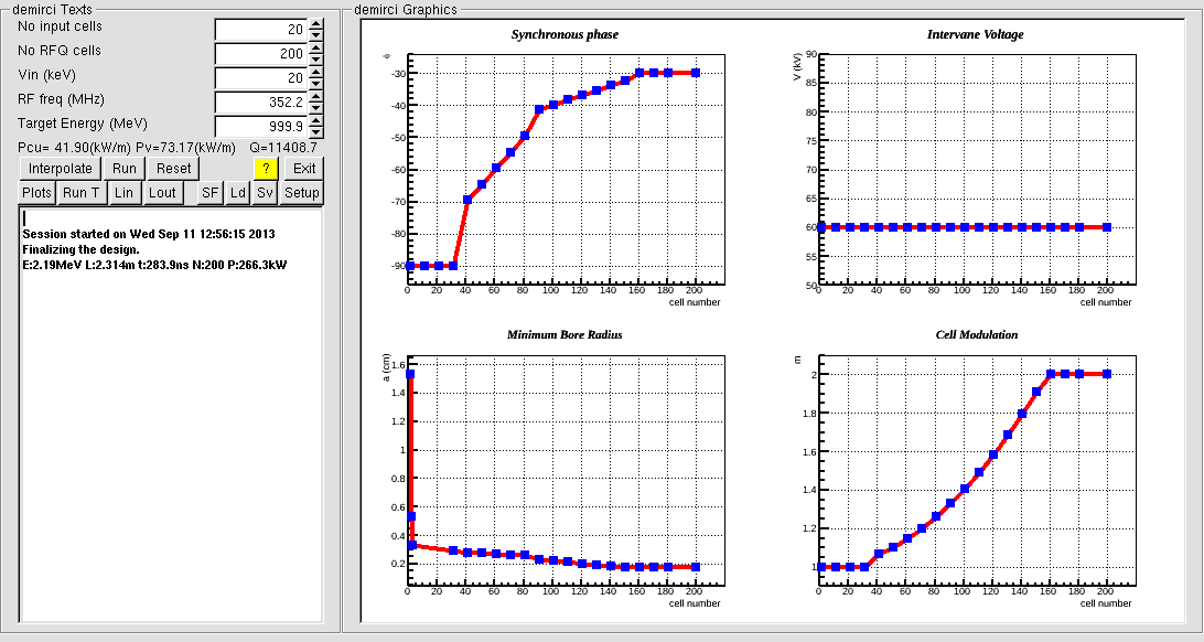
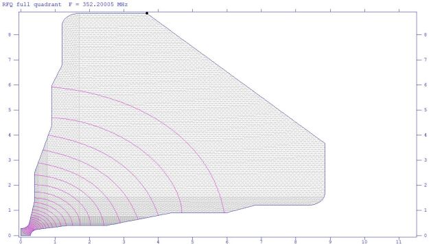
DEMIRCI, uses the classical RFQ formulas based on two term potential. It incorporates ROOT [7] library for user interaction and plotting facilities (see Fig. 3). It interfaces other available software like LIDOS, TOUTATIS [8] and SUPERFISH. It has also a command line interface, designed to be used in batch mode, where GNUPLOT is used for plotting. Although DEMIRCI results are found to be compatible with LIDOS and TOUTATIS within few percent error margin (see Table 2), its development continues as it does not yet provide CNC compatible vane design files. The difference between the results is believed to be originated from potential function expansions, i.e. 8 term multipole versus classical 2 term potential.
| Parameter | DEMIRCI | LIDOS | TOUTATIS |
|---|---|---|---|
| Length (m) | 1.555 | 1.585 | 1.549 |
| Energy (MeV) | 1.54 | 1.52 | 1.49 |
| Time (ns) | 249.9 | 265.8 | 243.8 |
| Transmission(%) | n/a | 99 | 97 |
3 RFQ Beam Dynamics
The SANAEM RFQ was designed using the Los Alamos National Laboratory’s (LANL) traditional Four Section Procedure (FSP). After the static design, the real vane shapes and actual beam dynamics were primarily calculated by ”LIDOS.RFQ.Designer” simulation code. In addition, a similar computer program, TOUTATIS, was used for beam dynamics design to validate the preliminary design by comparing it’s results with LIDOS. Two beam dynamics results obtained with TOUTATIS and LIDOS were compared with each other with the use of relevant DEMIRCI module. Additionally, LIDOS enables the segmentation of the RFQ design to the be with CNC manufacturing capabilities. The dividing gap is selected to be at cm with a separation of 1 mm. The resulting total structure is about 156 cm long, consisting of 176 cells with an inter-vane distance of 2.8 mm and a constant vane tip radius of 2.5 mm. The mismatch ratio is given by LIDOS as 1.03, which is a measure of the emittance match between the beam at the end of the LEBT and the ideal beam accepted by the RFQ. Also one should note that as the average current is modest, the space charge effects are negligible. Finally, the RFQ transmission is found to be about 99% for all particles and about 96% for accelerated particles. The beam dynamics design results are shown in Fig. 4 and Fig. 5.
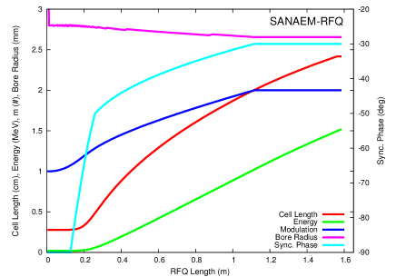
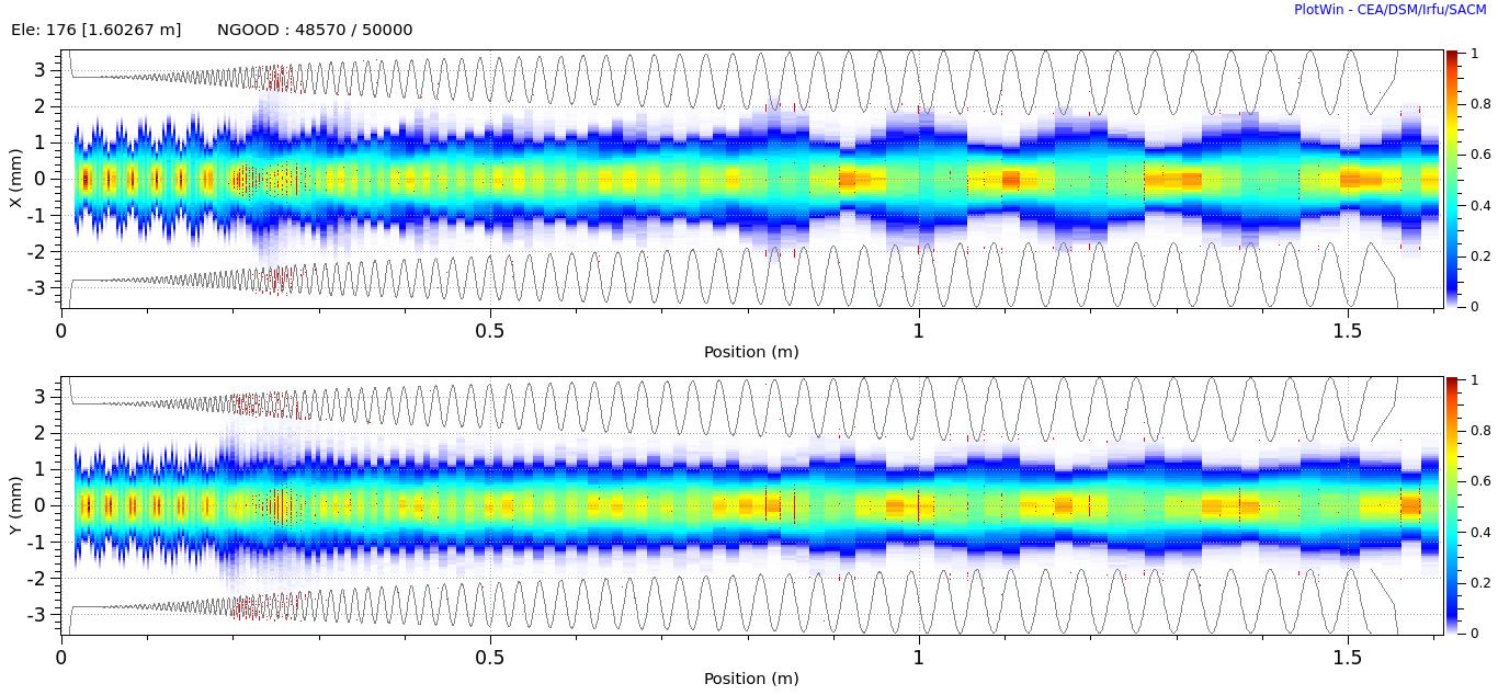
SANAEM RFQ exit ends with a Crandall cell which makes the beam properties time independent by canceling the phase difference between x and y dimensions. The proton beam at the RFQ exit can be guided by solenoid magnets into the next structure for further acceleration.
4 RFQ Electromagnetic Considerations
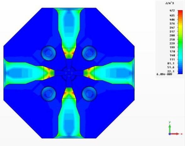
SANAEM RFQ electromagnetic studies were performed by using SUPERFISH, RFQFish and CST MWS [9] simulation programs to fine tune the cavity physical parameters. The first step was to start with the beam dynamics parameters and to achieve a preliminary design in 2D with Superfish which was subsequently optimized with RFQfish. The vane structure obtained after this last step was an input to CST MWS program which was used for 3 dimensional design. The cross sectional view and the geometrical properties can be seen in Fig. 6.
The quadrupole and dipole modes of the SANAEM RFQ are calculated by applying Neumann and Dirichlet boundary conditions and found 352.199 MHz with a quality factor of 10342 for the former, whereas the latter is at 341.903 MHz with a quality factor of 10173. The electrical energy density inside the SANAEM RFQ is shown in Fig 7. The power loss on the RFQ walls per quadrant is calculated to be 126 W/cm which gives a total ohmic loss of 91 kW at a total length of 164 cm which also include input and output matching sections. The volume power requirement has been calculated as 115 kW, which gives total power requirement of 206 kW. Including a conventional safety margin of 25% (50 kW) to account for losses in the transmission lines and RF connection, the RFQ power supply has to deliver 250 kW. Following the project principles, the RF power supply will be built by the local industry under the guidance of the project members. The RFQ operation will start in pulse mode with a relatively low duty factor of 5%. During the later stages of the operation, this value will be increased by upgrading the RF psu. The relevant (brief) list of physical parameters for the cavity is given in Table 3.
| Parameters | Superfish | CST MWS |
|---|---|---|
| Frequency (MHz) | 352.200 | 352.199 |
| Quality Factor | 10341.6 | 10216.4 |
| Power Dissipation (W/cm) | 123.5637 | 125.0779 |
| Kilpatrick Factor | 1.52 | 1.53 |
5 Mechanical Construction
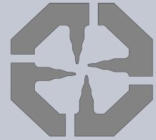
The choice of material, cross-sectional type and the assembly method were driven by local manufacturing constraints and row material accessibility. Therefore, the whole structure will be machined out of aluminum and coated with copper except vane-tips. The decision on the quadrant type and assembly technique has 4 criteria: CNC machining capability, RF considerations such as contact point optimization, easiness of assembling the manufactured pieces and laboratory work conditions. These criteria plus the availability of enough port (vacuum, RF input, cooling, etc…) area dictated a octagonal type geometry. Three possible major and minor vane manufacturing options are shown in Fig. 8. Detailed optimization and thermal analysis are ongoing to help with the final manufacturing decision. A novel idea of using silver paste between pieces and bolting through will be used for assembling procedure. The silver paste provides high RF and thermal conductivity and protection against high vacuum.


6 Current Status and Conclusions
As of September 2013, the last pieces of the ion source are being manufactured so that it can be assembled and tested before the end of the month. The LEBT solenoids and diagnostic stations are also being produced with the goal of doing the basic measurements (current, emittance, etc.) before the end of the year. As the design and production of the SANAEM RFQ is somewhat more challenging, a number of engineering models, i.e. so called cold model from Aluminum, will be used to understand the machining capabilities and to further test the other properties such as vacuum and low power RF. The first accelerated protons are expected to be available by the end of 2015.
7 ACKNOWLEDGMENT
The authors are grateful to TAEK for their enduring support and encouragements. The authors thank A. Bozbey and A. Tanrikut for useful discussions and comments.
References
- [1] T. Kalvas, et. al., IBSIMU: A three-dimensional simulation software for charged particle optics, Rev. Sci. Instrum. 81, 02B703, 2010.
- [2] SIMION 8.0 (Version 8 SIMION3D 8.0, SIMION™).
- [3] Perrin, A., et al., ”TRAVEL v4.07 User Manual”, CERN, April 2007.
- [4] J. Billen and L. M. Young, POISSON, SUPERFISH reference manual, LA-UR-96-1834.
-
[5]
LIDOS.RFQ.DESIGNER Version 1.3,
http://www.ghga.com/accelsoft/. - [6] G. Turemen, G. Unel, H.B. Yasatekin, DEMIRCI: a RFQ Design Code, in preparation.
- [7] R. Brun and F. Rademakers, ROOT - An Object Oriented Data Analysis Framework, Proceedings AIHENP’96 Workshop, Lausanne, Sep. 1996, Nucl. Inst. & Meth. in Phys. Res. A 389 81-86, 1997.
- [8] R. Duperrier, ”TOUTATIS: A radio frequency quadrupole code”, Phys. Rev. Vol.3, 124201, 2000.
- [9] CST Microwave Studio Suite User’s Manual, 2013.