Numerical analysis of the morphological and phase changes in the TiN/Al2O3 coating under high current electron beam modification
Abstract
A modification of the surface structure of the hybrid coating TiN/Al2O3 with a low-energy high-current electron beam (NCEB) is performed. The surface roughness is considered as a function of beam current. Surfaces of the obtained samples are investigated within the two-dimensional multifractal detrended fluctuation analysis (MF-DFA). The multifractal spectrum of the surface is calculated as a quantitative parameter of the roughness. It is shown that with an increase of the beam energy, the surface becomes more regular and uniform.
Key words: self-similarity, fractal dimension, hybrid coating, high-current electron beam(s) effect
PACS: 81.40.- z, 81.07.- b, 68.35.-p, 61.46.-w, 05.45.Df, 61.43.Hv
Abstract
Проаналiзовано процес модифiкацiї структури поверхнi гiбридного покриття TiN/Al2O3 пiд впливом низькоенергетичного сильнострумового електронного пучка. Шорсткiсть поверхнi розглянуто як функцiю струму пучка. Поверхнi отриманих зразкiв дослiджувались за допомогою двовимiрного мультифрактального флуктуацiйного аналiзу. Для кiлькiсного аналiзу змiни шорсткостi розрахована функцiя мультифрактального спектру. Показано, що зi збiльшенням енергiї пучка поверхня стає бiльш регулярною та рiвномiрною.
Ключовi слова: самоподiбнiсть, фрактальна розмiрнiсть, гiбридне покриття, НПЕП ефект
1 Introduction
Many objects and systems in nature exhibit a self-similar or self-affine structure [1, 2]. Self-similarity means that each segment of the initial set has the same structure as the whole object.The properties of such structures can be described by specific parameters, such as fractal dimension (or set of dimensions in the case of the multifractal objects [3]), Hurst exponent and others. Common examples of such objects are the Koch curve and the Cantor set. The property of self-similarity is inherent not only to topological structures but also to the phase space of complex stochastic systems with a hierarchical structure and non participant regions. The stochastic fractals can be illustrated through the Lorenz attractor and non-stationary time series [4].
The surface roughness characterization is an important problem for both applied and theoretical science. Many image techniques have been extensively used to investigate the rough surfaces, such as atomic force microscopy, secondary electron microscopy, optical imaging techniques and others [5]. It has been established [6] that the roughness parameters based on conventional theories depend on the sampling interval of a particular measuring instrument used. Using the methods of fractal geometry, this problem is eliminated because the fractal model includes topological parameters that do not depend on the resolution of the instrument used. The concept of fractal dimension, in contrast to traditional methods, has made it possible to explain the physical properties of the system depending on the geometry of the surface [7, 8]. For this purpose, many methods have been proposed, such as detrended fluctuation analysis (DFA) [9], two-dimensional multifractal detrended fluctuation analysis (2D MF-FDA) [10] a generalization of the 1D DFA and MF-DFA [11], rescaled range analysis [12] and many more [13].
In the present article we present the investigation of a self-similar structure of the TiN/Al2O3 hybrid coating surfaces using numerical methods of scaling analysis. Our calculations are based on the algorithm of two-dimensional multifractal detrended fluctuation analysis (MF-DFA) [9]. This algorithm was initially was developed for investigation of the time series as a one-dimensional self-similar set [14], and later on generalized for the analysis of more complicated objects [9]. Our calculations make it possible to present a quantitative characteristic of the surface roughness, and to compare it for different samples. Earlier in the work [15] we have considered the dependence of the generalized Hurst exponent surface of the coating TiN/Al2O3 at different beam current densities. However, a complete representation of multifractal formalism is achieved by calculating the multifractal spectrum and singularity strength . This knowledge would be useful because the roughness of hybrid coatings is an important factor at contact wear and physical phenomena such as absorption, catalysis and the dissolution of a fractal object.
The paper is organized as follows. In the opening section we briefly describe the object of our research — TiN/Al2O3 hybrid coatings, obtaining through plasma-detonation the technology and additional treatment by high-current electron beams (HCEB) at different regimes of partial melting. Next, we refer the main steps of the MF-DFA algorithm and present the results of our calculations, comparing them for different samples. The final section is devoted to discussion.
2 Samples under investigation
We used the -Al2O3 powder with a particle size of 27 to 56 microns as initial material for the deposition, which was applied in the facility ‘‘Impulse-5’’ on the substrate of austenite steel AISI 321 (18 wt.% Cr; 9 wt.% Ni; 1 wt.% Ti; 0.3 wt.% Cr; Fe the rest; 0.3 mm and 2 mm thickness) [16, 17, 18]. An oxide-aluminum ceramics and other coatings based on titanium carbide and tungsten carbide and nitrides possess a number of useful properties, which are capable of providing a corrosion protection, high hardness and mechanical strength, low wear and good electro-isolation properties. However, these coatings are characterized by the presence of macro-, micro- and submicroscopic porosity, and a certain number of defects [19]. For this purpose, to increase the corrosion resistance of protective ceramic coatings and to reduce the concentration of defects caused by deposition, the surface was coated with TiN layer. The deposition continued for 20 min in the atmosphere of ionized nitrogen, under 700 K temperature, and about to operation pressure of the reaction gas. The deposition TiN layer was made by means of the facility ‘‘Bulat-3T’’ with a vacuum-arc source (Kyiv, Ukraine).
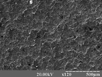
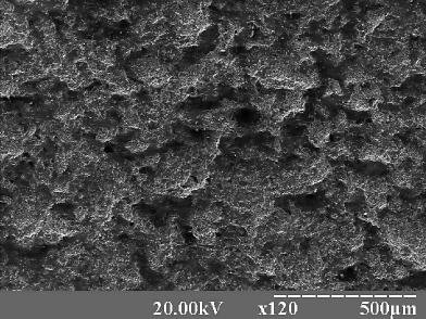
(a) (b)
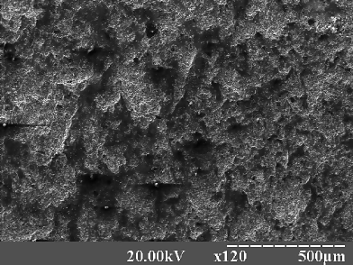
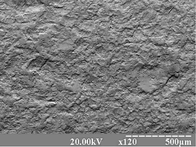
(c) (d)
One of the promising methods in solving the problem of adhesion of thin film coatings and reducing the roughness of the powder sublayer is a thermal treatment of the surface by high-current electron beams (HCEB) in the regime of partial melting. This technology made it possible to heal the micropores and to stimulate the diffusion processes between the deposited particles and layers.
It was found that the electron beam melting of hybrid coating surfaces TiN/Al2O3 (20 mA beam current) was accompanied by a partial melting of non-uniformities occurring in the surface structure (figure 1). It can be seen that the coating had a layered but melted structure. Regions of pit destruction were found on the surface (dark points seen in the photo). These craters appeared as a result of degassing induced by the electron beam melting of the surface layers. In addition, there were found light-color inclusions in the coatings. Repeated HCEB meltings of the coatings induced essential (even visible) changes in the surface relief.
During the second stage of melting, the geometry the surface layers of hybrid coatings depended on the electron beam power density. Correspondingly, the higher it was, the better these hybrid coating surfaces mixed and the more uniform they became. The thermal activation by the electron beam of coatings with the magnitude of 35 mA is accompanied by intense changes in the geometry of the surface layer. A complete fusion of the material near the surface is observed. The coating has a developed structure and represents a smooth alternation of peaks and valleys into each other, which is characterized by an appreciable decrease in the surface roughness.
3 Image analysis methodology
All surfaces were investigated within two-dimensional multifractal detrended fluctuation analyses (MF-DFA) methodology [14, 9]. This algorithm allows one to calculate the main parameters of the self-similar structure [1].
Self-similar surface is considered as a two-dimensional data array , where has discrete values and . itself is a surface obtained from the digital electronic microscopy image by decomposing it according to pixel indexes and brightness level . This surface is fragmented into non-overlapping segments of the sizes , where and are integer numbers.
For each segment identified by the cumulative sum :
| (3.1) |
is calculated for all segments . The next step is a detrending procedure for the obtained surface . The trend can be removed by the fitting procedure, when it is determined by some smooth polynomial function . There are many possible expressions of the function, but we choose the simplest one, in order to reduce the computational time:
| (3.2) |
where , , are coefficients defined by least-squares fitting algorithm. It should be mentioned that more complicated forms of do not provide any significant improvement of the precision of the method, but noticeably increase computational time [9]. After detrending we arrive at a residual function:
| (3.3) |
and a dispersion of the segment of length :
| (3.4) |
Dispersion of all the segments is calculated through averaging over all surfaces:
| (3.5) |
where is the deformation parameter initialized to increase the role of the segments with small (when ) or high () fluctuations , respectively. At , equation (3.5) takes the form (3.6):
| (3.6) |
according to l’Hôpital’s rule. For statistically correct results, the values must be varied within the range from to . The dispersion (3.5) and the segment size are linked through the scaling relation:
| (3.7) |
where is the generalized Hurst exponent.
Equation (3.7) can be rewritten according to the standard multifractal formalism through scaling exponent and partition function as [14]:
| (3.8) |
| (3.9) |
One can relate the Hölder exponent and the multifractal spectrum via Legendre transform [20, 21], deriving these multifractal parameters as
| (3.10) |
| (3.11) |
For monofractal objects, the function is a linear dependence which, with the transition to the multifractal, becomes more curved, keeping the linear sections within . In the analyzed structure, multifractality can be revealed more clearly from the shape of the multifractal spectrum , the width of which provides a set of fractal dimensions (for example, for monofractal curve has a -function with the fixed value).
4 Multifractal analysis of experimental results
In this section we apply the MF-DFA method to analyze the structure of the surface of the hybrid coating TiN/Al2O3 as shown in figure 1 at different magnitudes of the beam current.
![[Uncaptioned image]](/html/1310.1235/assets/x6.png)
![[Uncaptioned image]](/html/1310.1235/assets/x7.png)
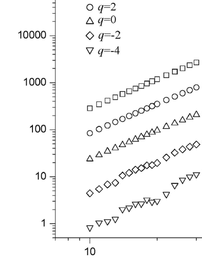
If the object under investigation has a self-similar structure, relation (3.7) is expected to be linear in double logarithmic scales. Figure 2 illustrates the dependence of the fluctuation function on the scale for different values of , calculated for TiN/Al2O3 surface modified by the beam current mA. As it follows from figure 2, the dependence has a clear linear part, which means that the surface of a hybrid coating has a self-similar structure. On the other hand, in the range where , the calculation is expected to yield a large error.
We have computed the mass exponent for different surfaces in the range . Figure 4 shows as a function of for hybrid coating surfaces under HCEB modification at different current magnitudes. The nonlinearity of indicates that the surface has a multifractal structure, i.e., it cannot be completely described by a single value of a fractal dimension . Different values of are related to the segments of the surface with different values of the fluctuation function . The latter is calculated as the difference of the surface local heights from some smooth fitting function. Thus, the set of the fractal exponents can be considered as a quantitative measure of the surface roughness. The strongest multifractality was observed for the surface being modified with the beam current magnitude mA, becoming more weaker with the growth of the beam current. It is shown that geometry of the surface layers of hybrid coatings depends on the electron density of the beam power.
We have calculated the values of the singularity strength function and the multifractal spectrum using equations (3.10) and (3.11). Figure 4 shows the spectrum for four samples under investigation. As it can be seen, the width of is different for the samples treated with different density of the beam current. The more uniform is the surface, the more restricted is the spectrum .
Minimum and maximum values of are important statistical parameters that describe the multifractal nature of fracture surfaces. These values are the singularity strengths associated with the region of the sets where the measures are the least and the most singular, respectively [10].
In the formalism of multifractals, is related to the maximum probability measure by , where represents the scale approaching zero and it is a small quantity, whereas is related to the minimum probability measure through . The width can be used to describe the range of the probability measures [10]:
| (4.1) |
The larger is , the wider is the probability distribution, and the strongest is the difference between the highest and the lowest growth probability.
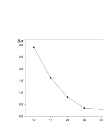
Figure 5 illustrates the relation between the width of the multifractal spectrum and different values of the beam current. As it can be seen, the width of the multifractal spectrum decreases with an increase of the current magnitude. The change of the surface relief, as shown in figure 5, proves the correspondence between the theoretical calculations and experimental results, i.e., with an increase of the beam current, the surface becomes more regular. A significant reduction of multifractal spectrum width with the increase of the current magnitude of 25 mA occurs due to remelting which smooths out the craters produced by degassing. A further increase of the beam current provides only an enhanced homogeneity of the structure and mass transfer processes between the layers composing the coating matrix. Figure 6 shows the dependence of phase composition on the singularity strength for hybrid coatings after duplex melting of their surfaces.
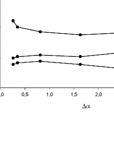
Special attention was paid to the change of concentration of the elements in the hybrid coating after duplex melting. It was shown in work [16] that the initial composition was about 60 wt. % of Al2O3. All the other phases and compounds comprised 40 wt. %.
As we can see from figure 6, with an increase of the density of the energy flow and, consequently, a decrease of the spectrum width, was accompanied by an insignificant increase in -Al2O3 amount. A further increase of the current led to a decrease in the percentage content of -phase from 58 wt. % to 50 wt. % and to an increase of -Al2O3 from 25 wt. % to 34 wt. %. The concentration of other phases and compounds underwent insignificant changes. Hence, a non-monotonous change of the phase percentage content was associated with an increase of the energy density. As a result, the surface of hybrid coating became more uniform by TiN and Al2O3 coating melting.
5 Conclusion
The mechanical studies demonstrated that hybrid coatings based on corundum and titanium nitride, which were modified by an electron beam until melted, possessed notably better servicing characteristics. Therefore, this technology could be applied to solve technical problems (for example, to decrease wear, to protect from corrosion, to increase adhesion and to improve nano- and micro-hardness).
Quantitative parameters of the surface structure obtained by the two-dimensional multifractal fluctuation method can be used to characterize the topology of the interface under modification. As shown by the numerical analysis, the character of surface morphology changed from high non-uniform roughness to smoothed regions with a gradual increase of the current density electron beam.
References
- [1] Feder J., Fractals, Plenum Press, New-York, London, 1998.
- [2] Olemskoi A., Danylchenko S., Borisyuk V., Shuda I., Metallofiz. Noveishie Tehknol., 2009, 31, 777.
- [3] Olemskoi A.A., Fractal in Condensed Matter Physics, In: Physics Reviews, 1995, 18, Part 1, 1.
- [4] Olemskoi A.A., Synergetics of Complex Systems: Phenomenology and Statistical Theory, KRASAND, Moscow, 2009 (in Russian).
- [5] Arnéodo A., Decoster N., Roux S.G., Eur. Phys. J. B, 2000, 15, 567; doi:10.1007/s100510051161.
- [6] Jeng Y.R., Tsai P.S., Fang T.H., Microelectron. Eng., 2003, 65, 406; doi:10.1016/S0167-9317(03)00052-2.
- [7] Pfeifer P., Wu Y.J., Cole M.W., Krim J., Phys. Rev. Lett., 1989, 62, 1997; doi:10.1103/PhysRevLett.62.1997.
- [8] Borisyuk V.N., Kassi J., Holovchenko A.I., J. Nano-Electron. Phys., 2011, 3, No. 4, 20.
- [9] Gu G.F., Zhou W.X., Phys. Rev. E, 2006, 74, 061104; doi:10.1103/PhysRevE.74.061104.
- [10] Liu C., Jiang X.L., Liu T., Zhao L., Zhou W.X., Yuan W.K., Appl. Surf. Sci., 2009, 255, 4239; doi:10.1016/j.apsusc.2008.11.014.
- [11] Niu M.R., Zhou W.X., Yan Z.Y., Guo Q.H., Liang Q.F., Wang F.C., Yu Z.H., Chem. Eng. J., 2008, 143, 230; doi:10.1016/j.cej.2008.04.011.
- [12] Hurst H.E., Trans. Am. Soc. Civ. Eng., 1951, 116, 770.
- [13] Olemskoi A., Shuda I., Borisyuk V., Europhys. Lett., 2010, 89, 50007; doi:10.1209/0295-5075/89/50007.
- [14] Kanthelhardt J.W., Zscheinger S.A., Koscienly-Bunde E., Havlin S., Bunde A., Stanley H.E., Physica A, 2002, 316, 87; doi:10.1016/S0378-4371(02)01383-3.
- [15] Pogrebnyak A.D., Borisyuk V.N., Bagdasaryan A.A., In: Proceedings of the International Conference ‘‘Nanomaterials: Applications and Properties’’ (Alushta, 2012), Vol. 1, 2012, 02NFC27.
- [16] Pogrebnyak A.D., Kravchenko Yu.A., Kislitsyn S.M., Ruzimov Sh.M., Noli F., Misaelides P., Hatzidimitriou A., Surf. Coat. Technol., 2006, 201, 2621; doi:10.1016/j.surfcoat.2006.05.018.
- [17] Pogrebnjak A. D., Ponomarev A.G., Shpak A.P., Kunitskii Yu.A., Phys. Usp., 2012, 55, 270; doi:10.3367/UFNe.0182.201203d.0287.
- [18] Pogrebnyak A.D., Sobol O.V., Beresnev V.M., Turbin P.V., Il’yashenko M.V., Kirik G.V., Makhmudov N.A., Shypylenko A.P., Kaverin M.V., Tashmetov M.Yu., Pshyk A.V., In: Nanostructured Materials and Nanotechnology IV: Ceramic Engineering and Science Proceedings, 2010, 31, 127; doi:10.1002/9780470944042.ch14.
- [19] Kunchenko Yu.V., Kunchenko V.V., Nekliudov I.M., Kartmazov G.N., Andreev A.A., Probl. Atomic Sci. Technol., 2007, 2, 203.
- [20] Peitgen H., Jürgens H., Saupe D., Chaos and Fractals: New Frontiers of Sciences, Springer-Verlag, New-York, 1992.
- [21] Halsey T.C., Jensen M.H., Kadanoff L.P., Procaccia I., Shraiman B.I., Phys. Rev. A, 1986, 33, 1141; doi:10.1103/PhysRevA.33.1141.
Ukrainian \adddialect\l@ukrainian0 \l@ukrainian
Чисельний аналiз морфологiчних та фазових перетворень покриття TiN/Al2O3 пiд час модифiкацiї низькоенергетичним сильнострумовим електронним пучком О.Д. Погребняк, В.М. Борисюк, А.А. Багдасарян
Сумський державний унiверситет , вул. Римського-Корсакова, 2, 40007 Суми, Україна