Mechanism for Radiation Damage Resistance in Yttrium Oxide Dispersion Strengthened Steels
Abstract
ODS steels based on yttrium oxide have been suggested as potential fusion reactor wall materials due to their observed radiation resistance properties. Presumably this radiation resistance can be related to the interaction of the particle with vacancies, self-interstitial atoms (SIAs) and other radiation damage debris. Density functional theory has been used to investigate this at the atomic scale. Four distinct interfaces, some based on HRTEM observations, between iron and yttrium oxide were investigated. It is been shown that the Y2O3-Fe interface acts as a strong trap with long-range attraction for both interstitial and vacancy defects, allowing recombination without altering the interface structure. The catalytic elimination of defects without change to the microstructure explains the improved behaviour of ODS steels with respect to radiation creep and swelling.
1 Introduction
Fusion energy has the potential to provide clean and abundant power for future generations[1]. Many designs have been suggested to make this a reality: These include the tokamak[2] and inertial confinement[3]. Current facilities attempting to realise these designs are, respectively, the International Thermonuclear Experimental Reactor (ITER) in France, which is under construction, and the National Ignition Facility (NIF) in California. Regardless of design, any fusion reactor would have to withstand the intense neutron radiation ITER is predicted to produce a flux rate of at least 1 MW m-2 at its walls[4], equivalent to fifty thousand 14.1 MeV neutrons incident per square centimetre every nanosecond.
Thus, it is critical to find materials that are resistant to neutron radiation at elevated temperatures. There have been a large number of other experiments on irradiated ODS [7, 8, 9, 10, 11, 13, 14, 15, 16] balance of experimental evidence suggests that ODS steels exhibit a lower level of swelling and creep than equivalent steels without ODS dispersoids. For example, a strong candidate material for the inner wall of a fusion reactor is the EUROFER97 ferritic/martensitic steel, a chromium-rich iron alloy. Oxide dispersion strengthened steels[5] based on EUROFER97 can be constructed through a sequence of mechanical alloying and hot isostatic pressing processes to incorporate yttrium oxide into the metal[6]. These ODS steels typically hold between between 0.3 and 0.5% yttrium oxide by weight[7], and are remarkably durable, with the form of yttria grains remaining stable after 590 MeV proton irradiation up to doses of 1.0 displacements per atom (dpa)[8]. These experiments have observed the increased yield stress of ODS steels compared to the standard EUROFER97 steel to be further enhanced under this level of irradiation. Other improvements include increased ultimate tensile strength, by a factor greater than 1.5, persisting up to 650∘C; the creep strength at 700∘C is equal to that of the base steel at 600∘C[7] and a 30-40% greater yield strength[8].
Some less ideal properties of the ODS steel include a reduced elongation on fracture at high temperature and raised ductile-to-brittle-transition temperature, rendering the ODS steel brittle at room temperature, has been observed[7, 8]. However, both high temperature elongation and ductility can be improved by the inclusion of titanium impurities[8]. These properties of ODS steel suggest that reactor operating temperature could be increased by 100K or more, compared to the base EUROFER97.
Suggested reasons for the radiation resistance exhibited by ODS steels have been summarised by Schäublin[8]. One idea is that the oxides provide a catalyst for annihilation of the structural defects (vacancies and SIAs caused by radiation (see Section 2). This could either be due to some attraction between the oxide and the defects, or altered defect dynamics at the interface boundary combined with the high density of particles. Another idea is that the disorder already brought about by the oxide dispersions in the steel structure make further disruptions caused by radiation less effective in weakening the material. A third is based on the original purpose of ODS: that the increased density of pinned dislocations aids recombination.
We investigate the recombination-catalyst idea for the idealised case of ferritic iron and pure yttrium oxide (Y2O. We use density functional theory (DFT) simulations of possible interfaces between the oxide and the metal. This allows for modelling of the behaviour of radiation induced defects near the interface. In particular, the question to be answered is whether these atomic scale methods will be able to provide an explanation for the impressive performance of ODS steels under irradiation. Additionally, it would be desirable if this explanation would give a clue to improving these materials’ properties.
Pure iron has a simple body-centred cubic lattice structure up to 1043 K, which contains the entirety of the operating temperature limits for a fusion reactor wall [6]. A 14.1MeV neutron penetrate deep into the metal and eventually collide with a lattice atom, this initiates a “displacement cascade” which creates vacancy and SIA defects in equal numbers. [17]
The displacement cascade is a rapid process (of order picoseconds). Further migration of vacancies and SIAs, mainly by diffusion, happens over a timescale of order nanoseconds[17]. This is still short compared to operating times, so is important to consider the equilibrium result of such processes: If the vacancies and SIAs were likely to find their Frenkel partner, recombine, and annihilate, then the metal should essentially return to its original structure; however, if defects instead formed large clusters of a single type this could result in formation of voids, dislocation loops or swelling, possibly weakening the material in the process. Defects can be trapped at grain boundaries or surface, so for an ODS particle to effect the diffusion, there concentration must be such that there are many such particles in each grain.
Atomic impurities dispersed throughout the metal play a significant role in point defect dynamics[17]. From elastic considerations, one might expect that substitutional impurities would attract SIAs, and oversized substitutional and interstitial defect attract vacancies. However, the stable SIA configuration iron is the (110) dumbbell, which has a quadrupole strain field with both tensile and compressive regions - thus the SIA binds to most impurities. Moreover, the magnetic structure of iron can lead to complex binding where the idea of “big” or “small” atoms is oversimplistic - for example Cr behaves like an undersized defect interacting with defects, but when added to Fe increases the lattice parameter; Ni is exactly opposite[20]. Recent DFT simulations[24, 25, 26, 27], in iron lattices, have shown well defined trends across the periodic table for defect binding in both fcc and bcc iron.
2 Yttrium Oxide in Iron
2.1 Pure Yttrium Oxide
The structure of pure yttrium oxide, , is described by the space group,[28] which has body-centred symmetry. This structure can be represented by an 80 atom cubic unit cell, with a lattice constant of 10.604 ,[28] or a 40 atom primitive cell.
Specifically, the 32 yttrium atoms in the cubic unit cell are on the Wyckoff 8a and 24d sites, with oxygen atoms at 48e . Previously obtained values of lattice parameter () are given in table 1.[29, 30, 31]
| Method | |||||
|---|---|---|---|---|---|
| X-Ray Diffraction [29] | 10.6 | 0.3895(4) | 0.1509(3) | 0.3820(4) | 0.03203(6) |
| Empirical potential [30] | 10.6 | 0.3906 | 0.1513 | 0.3797 | 0.0325 |
| Density Functional Theory [31] | 10.46 | 0.3903 | 0.1506 | 0.3805 | 0.0283 |
| This work | 10.7 | 0.3910 | 0.1516 | 0.3798 | 0.0326 |
| Approximated | 0 |
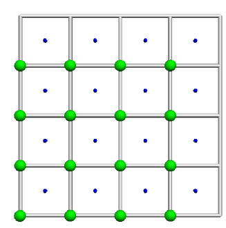
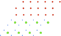
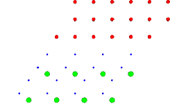
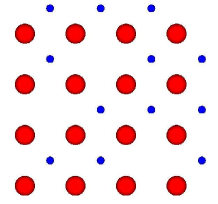
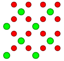
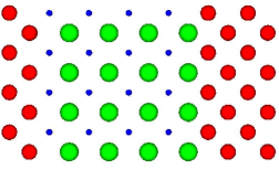
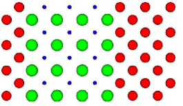
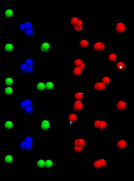
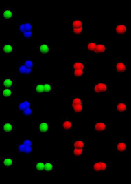
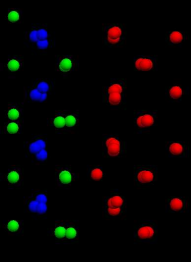
Note that the structural parameters are quite close to integer multiples of . Rounding these to the nearest such values approximates the yttrium and oxygen atoms to be located on vertices and centres, respectively, of cubes comprising a 4x4x4 grid. From this viewpoint the oxygen atoms occupy two thirds of the possible 64 sites, while the yttrium atoms occupy half (Fig. 1)
2.2 Interface Characterisation
In order to account for the observed radiation resistant properties of yttria-based ODS steels, the microstructure of the oxide dispersions in bulk iron must be considered. The dispersion of the nanoparticles throughout the steel has been observed to be largely homogeneous,[33] with a typical density of about one nanoparticle per [34]. Generally, the nanoparticles are spherical with a diameter on the order of ten nanometres, but larger nanoparticles tend to form pronounced faceted surfaces with no evidence of large interfacial strain[6].
Orientation correlations of the nanoparticle with the steel matrix have been observed using High Resolution Transition Electron Microscopy (HRTEM)[6, 35, 36], and for the EUROFER97-based ODS steel the dominant orientation correlation is ‘ and ’, where the aligned directions and Miller indices of the interface are specified.
Detailed measurement of energetics of the interface and its interactions are needed to show whether the nanoparticles act as attractive sinks for point defects. Here we use DFT to investigate this for two orientation correlations: the observed EUROFER97 correlation specified above and a simpler ‘ and ’ which also involves low strain mismatch.
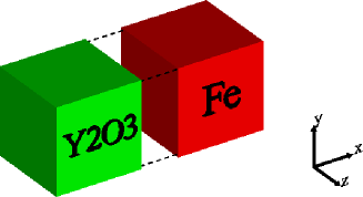
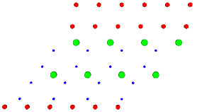
2.2.1 Structure of Simple Interface and
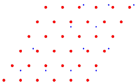
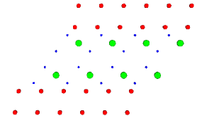
This interface is constructed by simply placing the two cubic structures side by side and joining them at a cube face. The ratio between the yttrium oxide and iron lattice constants is 3.7. This suggests a supercell with the periodicity of the cubic unit cell matches bcc iron cells. The strain in each structure from this fit is 4.0%. The orientation is uniquely defined due to the cubic symmetry, but the truncation of the slab may be either at O or Y atoms. Thus, the two cases of the iron bonding to the oxygen or yttrium must both be investigated, let these interfaces be referred to as (100)Fe-O and (100)Fe-Y respectively. A schematic of how these two setups might be constructed is shown below. Note the continuation of the bcc structure into the interface.
| (100)Fe-O | Key: | (100)Fe-Y |
 |
 |
|
|
|
||
|
|
||
|
|
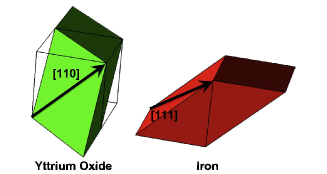
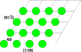
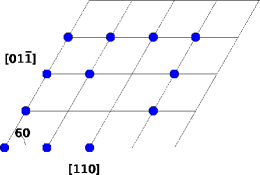
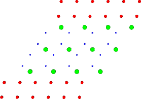
2.2.2 Structure of Klimiankou Interface: and
The orientation of the interface observed in EUROFER97[6] is slightly more complicated as the two planes are of different types. The interface model is best visualised by cutting the cubic unit cells along the relevant plane and shifting by a lattice vector, forming parallelepipeds each with two faces of the required type. If an arrow is drawn along the correlated directions on the respective faces, the interface is oriented by making both these arrows parallel. Again, due to symmetry, all orientations ‘ and ’ type are accounted for by this specific orientation correlation.
There are two distinct planes of the type in , one containing 16 yttrium atoms and the other with 12 oxygens. They can be thought of as atoms located on the vertices of a parallelogram grid, with some vertices empty in the case of oxygen. Consequently, iron-yttrium and iron-oxygen interfaces are both possible. Furthermore, there are two varieties of the iron-oxygen interface: The next layer into the oxide could be either a yttrium or another oxide layer. We label the candidate interfaces KlimFe-Y-O, KlimFe-O-Y and KlimFe-O-O, as depicted in figure 5.
The ratio between lengths in the correlated directions is . Thus a strain of only 0.4%, is required with three iron parallelepipeds joined corner-to-corner along the arrows depicted in figure 3. In the perpendicular direction the misfit can be accommodated by a shear in the iron lattice resulting in an increase of the angle between the and directions from to .
| Yttrium | Oxygen | Iron |
|---|---|---|
 |
 |
 |
| Fe-Y-O | Fe-O-Y | Fe-O-O |
|---|---|---|
 |
 |
 |
3 Computational Details
To calculate the interfacial energies, we use the Density Functional Theory as implemented in the Vienna Ab Initio Simulation Package (VASP)[37] using the projector augmented-wave (PAW) method[38] with eight(Fe), six(O) and eleven(Y) valence electrons and the spin polarised PBE exchange-correlation functional[39] with a 520eV cutoff energy for the plane wave basis set. The interface supercells contained over 200 atoms, and the largest calculations used k-point Monkhorst-Pack mesh (with the lower number of k-points in the longer direction). All atoms were fully relaxed from the “ideal” geometries described above. These settings are known from previous work to be reliable[19, 20, 21, 40].
The stability of the interface was determined by the work of adhesion for stoichiometric setups. The effect of creating iron vacancies and SIAs both at and near the interface was investigated by comparing the relative energy change with that in pure iron after ionic, but not volumetric, relaxation. between consecutive steps was less than eV. The chemistry of the binding was investigated from the density of states projected on atoms near the interface.
To calculate the reference energy cost of forming vacancies and SIAs in pure iron, we used a 256 atom supercell. Lattice constant (2.87Å), magnetic moment (2.2) vacancy (=2.16eV) and (110)-SIA (=4.02eV) energies in iron were consistent with previous work[19, 20, 21]. The calculated lattice parameter of Y2O3 is 10.7 , and its structural parameters, are given in table 1. Our results are comparable to recent studies of Y and O impurities in bcc FeCr[22, 23]. Y has a substitutional energy in Fe of 2.01 eV and Oxygen 0.13eV relative to metal and gas state respectively.
4 Stoichiometry and Interfacial Energy
Interfacial energy can be calculated when the yttrium to oxygen ratio in the supercell is stoichiometric with yttrium oxide i.e. 2:3. For example, if a supercell, with total energy F, contains iron particles and a total of yttrium and oxygen particles then the associated interfacial energy would be:
| (1) |
Where A is the total interfacial area in the supercell and =-8,212eV, are the VASP chemical potentials per atom for iron and Y2O3. These absolute values have no physical meaning, being the energy gained in forming the perfect solid from a non-spin-polarised pseudoatom, but can be compared to the metallic Y (-6.26eV), molecular oxygen (-4.92eV) Y substitutional in Fe (-8.27eV) and O interstitial in Fe (-5.05eV) to show that Y and O will dissolve in Fe, but would prefer to form the oxide.
5 Supercell Geometries
5.1 (100) Interfaces
Three supercells involving (100) interfaces were investigated: one considering two (100)Fe-O interfaces, one considering two (100)Fe-Y interfaces and the third considering one of each. The single-type setups are denoted by the corresponding interface, the mixed interface is called (100)Mixed. Only the mixed interface has the stoichiometry needed for calculating the surface energy. Periodic boundary conditions are used, and at the interfaces the iron atoms were placed to continue the bcc structure into the yttrium oxide as shown in figure 6. The number of atoms in each supercell is given in table 2.
| Number of atoms | |||
|---|---|---|---|
| Setup | Iron | Oxygen | Yttrium |
| (100)Fe-O | 112 | 60 | 32 |
| (100)Fe-Y | 112 | 36 | 32 |
| (100)Mixed | 96 | 48 | 32 |
| KlimFe-O-Y | 180 | 48 | 32 |
| KlimFe-Y-O | 144 | 48 | 48 |
| KlimMixed | 180 | 48 | 32 |
| (100)Fe-O | Key: | (100)Fe-Y |
 |
 |
|
|
|
||
|
|
||
|
|
| (100)Fe-O | (100)Mixed | (100)Fe-Y |
|---|---|---|
 |
 |
 |
5.2 Klimiankou Interfaces
Two variations of the HRTEM interfaces[6] have also been investigated: a stoichiometric setup with two single-O layer interfaces (denoted KlimFe-O-Y), a non-stoichiometric setup with two KlimFe-Y-O. Various setups containing KlimFe-O-O interfaces were attempted, but underwent massive spontaneous reconstruction indicating instability. However, one stoichiometric setup (KlimMixed), also containing a KlimFe-Y-O interface was relaxed enough to achieve acceptable formation energy results. The lattice vectors of the supercell were in the [010], [110] and [01] directions. The number of atoms in each cell are given in table 2.
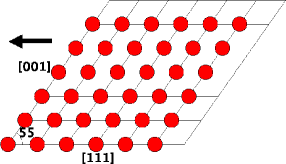
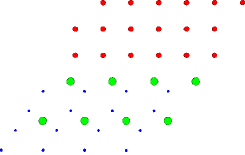
BCC iron [111] planes have hexagonal structure, with directions in this plane initially matched those of the corresponding pure yttrium oxide cell. The iron atoms at the interface were initialised to give the smallest interplanar distance, assuming fixed interatomic distances. An example of how this was achieved in the Fe-O case is shown in figure 7. The number of iron planes was determined by requiring that the fit would be similar at top and bottom of the interface. The setups resulting from periodic boundary conditions are shown in figure 7.
KlimFe-O-Y
KlimMixed
KlimFe-Y-O
5.3 Point Defects
After the supercells were relaxed, vacancies were formed by removing iron atoms and SIAs by replacing one iron atom with a dumbbell such that nearest-neighbour distances were maximised. Up to four SIAs or vacancies at the interface were investigated for each case. The low symmetry ensures that a local minimum energy configuration is found, but all sites in the interface are inequivalent (see Fig.7), so an exhaustive combinatoric search is impractical. Thus we selected sites with particularly high or low atomic density. For example, SIAs were often inserted in large gaps along, and vacancy sites chosen by removing Fe atoms closest to their adjacent O or Y. Additionally, the effect of creating a single point defect in planes further away from the interface was investigated, and in some cases this led to a more stable structure.
We define the defect energies in the interface relative to defect in the lattice. Thus if the defect-free interface calculation has energy , and the calculation of the interface with M extra Fe atoms has energy , then the formation energy per defect is given by
A similar definition is used for vacancies.
6 Results
6.1 Interfacial Energy
The energy needed to form the stoichiometric interface combinations from the pure components, and the associated surface energy, , are given in table 8. It can be seen that the interfaces observed experimentally do indeed have lowest energy.
| Interface | Formation Energy / eV | / eV | / J |
|---|---|---|---|
| (100)Mixed | 50.0 | 0.215 | 3.45 |
| KlimFe-Y-O | 65.0 | 0.163 | 2.60 |
| KlimMixed | 73.2 | 0.182 | 2.91 |
We investigated the local electronic density of states projected onto each atom. The main feature is that from an electronic point of view, the interfaces are sharp, with the chemically-expected Y3+ and O2- ions. The classical method for estimating metal-ionic interface binding involves the induction of “image charges” in the metal: there is no evidence of any physical image charges underpinning this calculational trick. The oxygen valence states lie below Fe d-band, while the yttrium d-states lie slightly above the iron d-band, well above the Fermi energy. Thus there is no metallic or covalent bonding across the interface. The sharpness of the interface explains why the calculations of interface energy converge rapidly with supercell size, even for non-stoichiometric cells.
6.2 Point Defects
Figure 9 shows the change in energy as the number of defects at the interface is altered by adding and removing iron atoms. It can be seen that in some cases there is a negative formation energy for defects in the (100) interface - this is further evidence of the instability of that interface. In all cases, the energy costs of vacancy and SIA creation at all interfaces were found to be consistently less than in bulk iron. Consequently the ODS particle acts as a trap for both types of defect.
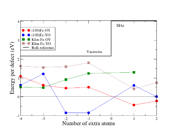
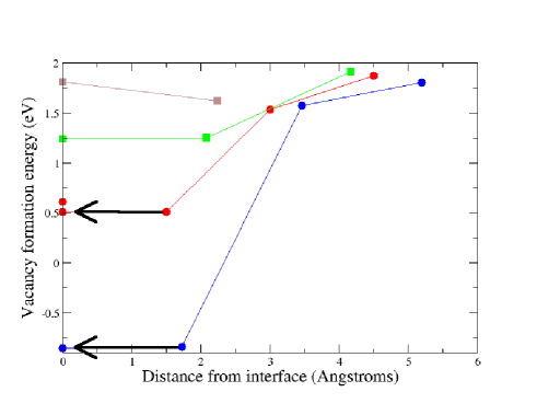
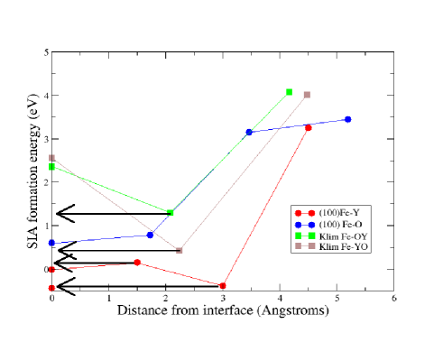
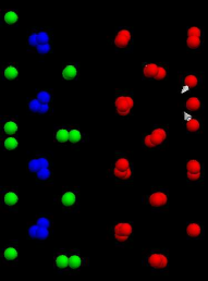
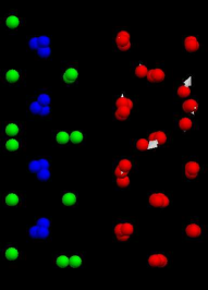
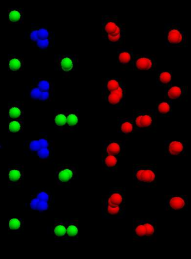
Figure 10 shows the point defects energetics at sites further away from the interface. Importantly, this is only a subset of the calculations we performed. In many cases defects that were created one layer from from the interface spontaneously relaxed into interface. This was particularly the case with SIAs near iron-yttrium interfaces as is depicted in figure 11 for the case of the (100)Fe-Y interface. The implication is the that the final step of capture of defects by ODS particles is essentially barrierless. It is also worth noting that, in some cases, the configuration obtained from interstitial migration has lower energy than the defect relaxed in the interface. This implies the existence of many low energy interface sites for absorption of SIAs and vacancies, and of easy migration within the interface. Interface interstitial configurations set up with (001) dumbbell iron atoms relaxed to metastable energies of 2.36eV (KlimFe-OY) and 2.56eV (KlimFe-YO). These energies (less the stable formation energy 1.30/0.43) place a limit on the migration barriers in the interface.
 |
 |
 |
|
 |
 |
As progressively more atoms are removed from the interface, the integrity of the layer itself is compromised. Trivially, removing (or adding) 16 atom from/to an iron layer (and allowing for a realigning relaxation) is exactly equivalent to recreating the perfect interface, and would have zero “energy per defect”. 15 vacancies would be equivalent to one interstitial etc. An interesting conformation is to remove a complete row of 6 atoms at the KlimFe-O-Y, essentially creating a misfit dislocation. This resulted in an energy increase of 3.19 eV (0.53eV/vacancy)
7 Discussion
DFT is now well established as a reliable technique for describing these types of material, so the agreement with experiment for the perfect materials and superior stability of the Klim interfaces is no surprise. The large planar separation, high particle density and low misfit strain are contributing factors to its stability. Stoichiometry makes it impossible to define the stable interface: the Klim-Fe-O-Y termination is certainly more stable than the average of Klim-Fe-O-O and Klim-Fe-Y-O interfaces. However reconstruction suggests that the double-oxygen layer at the KlimFe-O-O is least favoured, probably due to low binding between the double oxygen layer, so Klim-Fe-Y-O may be low energy.
Electronic wavefunctions are attenuated before the second plane of atoms. This suggests that the interface is sharp, and electronic effects do not significantly affect the electronic structure away from the interface. Thus most long-range behaviour could be attributed to ‘physical’ rather than ‘chemical’ effects.
For nuclear applications, the most important results concern the energetics of point defects. In all cases both SIA and vacancy defects are much more stable at the interface than in the bulk iron, and multiple defects can be accommodated simultaneously. Moreover, if a full layer of Fe atoms is created/removed the interface is perfectly restored, so there is no effect dues to sink strength bias. Crucially, unlike grain boundaries, surfaces and other sinks, the oxide nanoparticle is unaffected by the flow of defects. Incoming vacancies were not observed to trigger the outward diffusion of Y or O atoms into the steel. Consequently, ODS particles are perfectly capable of absorbing defects without contributing to swelling, hardening, creep etc. Thus our calculations provide strong evidence in favour of the catalyst model of the action of ODS particles [8]
Furthermore, the energy gradients in figure 10 for the (100) interfaces and numerous barrier-free pathways for inward migration of SIAs near iron-yttrium interfaces suggest a long range ‘attraction’ of the interface to point defects[41].
We note that additional alloy elements present in EUROFER97 were not considered. In fact, an energy-dispersive X-ray study on the EUROFER97-based ODS steel has shown that the chromium and vanadium present in the alloy form thin shells around the nanoparticles[42], presumably attracted by the strain fields. These elements have their own attraction for point defects, and consequently could be important in modifying the interface properties. Unfortunately, this possibility has had to be neglected in this present investigation.
In sum, our study shows that the ODS-Fe interface has a strong attraction for vacancy and interstitial defects, and provides strong support for a “catalytic” model of point defect removal and consequent radiation resistance.
8 Acknowledgements
We wish to acknowledge the use of the EPSRC funded Chemical Database Service at Daresbury[32], and the UKCP collaboration for supercomputer time (HECToR). This work was inspired by the FP7-Getmat project.
References
- [1] M. Homma in Future prospects of nuclear fusion energy, Proc. of the 2nd Int. Symp. on Lib. Arts and General Edu. Kyoto University, eds. P.H. Harvey and L. Partridge,p24 2011
- [2] P. Helander et al. Plasma Phys. Control Fusion 54 124009 (2012)
- [3] L. J. Perkins et al, Phys. Rev Lett. 103 045004 (2009)
- [4] F. W. Perkins et al. Nucl. Fusion 39(12) 2137 (1999)
- [5] R. L. Klueh et al, J. Nucl. Mater. 241 103 (2005)
- [6] M. Klimiankou et al, J. of Crystal Growth 249 381 (2003)
- [7] R. Lindau et al. J. Nucl. Mater 307 769 (2002)
- [8] R. Schäublin et al. J. Nucl. Mater 351 247 (2006)
- [9] G.R. Odette, M.J. Alinger and B.D. Wirth Annual Review of Materials Research 38 471-503 (2008)
- [10] J. Saito et al. J. Nucl. Mater 258 1264 (1998)
- [11] M.B. Toloczko, D.S. Gelles, F.A. Garner, R.J. Kurtz, K. Abe, J. Nucl. Mater. 329-333 352 (2004)
- [12] M.B. Toloczko, F.A. Garner, and S.A. Maloy, J. Nucl. Mater. 428 170-175 (2012)
- [13] J. Chen and W. Hoffelner J. Nucl. Mater., 392 pp. 360 (2009)
- [14] J. Chen et al. J. Nucl. Mater., 437, 432 (2013)
- [15] I.S. Kim et al. J. Nucl. Mater., 280, 264 (2000)
- [16] C.H. Zhang et al. J. Nucl. Mater., 386 457 (2009)
- [17] G. S. Was ”Fundamentals of radiation materials science: Metals and alloys”, isbn 978-3-540-49471-3, Berlin Heidelberg: Springer-Verlag p155 (2007)
- [18] C. Domain and C. S. Becquart, Phys. Rev. B 65, 024103 (2001)
- [19] C.C.Fu, F.Willaime and P.Ordejon Phys.Rev.Letters, 92 175503 (2004)
- [20] T.P.C. Klaver, D.J. Hepburn and G.J. Ackland, Phys. Rev. B85, 174111 (2012).
- [21] P. Olsson, C. Domain and J. Wallenius, Phys.Rev.B 75 014110 (2007)
- [22] A. Claisse and P. Olsson, J.Nucl.Mater. http://dx.doi.org/10.1016/j.nimb.2013.01.016, in press (2013)
- [23] Y Jiang, J.R.Smith and G.R.Odette, Phys.Rev B 79, 064103 (2009)
- [24] A. Gopejenko, Nanodevices and Nanomaterials for Ecological Security, eds. Y. N. Shunin and A. E. Kiv, Springer , Dordrecht, p149, (2012)
- [25] L.Malerba, et al. J.Nucl.Mater. 406, 1, 7 (2010)
- [26] D.J.Hepburn, G.J. Ackland and P.Olsson Phil.Mag 89 34-36 3393 (2009)
- [27] D. Murali, B.K. Panigrahi M.C. Valsakumar, S. Chandra, C.S. Sundar, and B Raj J. Nucl. Mater 403, 1–3, 113 (2010)
- [28] Y. Xu, Z. Gu and W.Y. Ching, Phys. Rev. B, 56, 23, 14993–15000 (1997)
- [29] Z. K. Heiba and L. Arda, Crys. Res. Tech., 43, 282–288 (2008)
- [30] K. Umemoto and R. M. Wentzcovitch, Phys. Chem. Minerals, 38, 387–395 (2011)
- [31] L. P. Putilov, J. Phys. Chem. Solids, 72, 1090–1095 (2011)
- [32] D. A. Fletcher et al, J. Chem. Inf. Comput. Sci., 36, 746-749, (1996)
- [33] R. Lindau et al, J. Nucl. Mater., 307-311, 769-772, (2002)
- [34] V. de Castro et al. Mater. Sci. Tech. 27 719 (2011)
- [35] L. L. Hsiung, Microscopy 1, 1811-1919, (2010)
- [36] R. Behr, Intermetallics, 7, 423-436, (1999)
- [37] G. Kresse and J. Hafner, Phys. Rev. B 47, 558 (1993);
- [38] P.E. Blöchl, Phys. Rev. B 50, 17953 (1994); G. Kresse and D. Joubert, Phys. Rev. B 59, 1758 (1999).
- [39] J. P. Perdew, K. Burke, and M. Ernzerhof Phys. Rev. Lett. 77, 3865 (1996)
- [40] L. Zhu, Q.-M. Hu, R. Yang, G. J. Ackland: J. Phys Chem C 116 4224-4233 (2012)
- [41] X.M. Bai et al., Science 327 5973 1631 (2010); G. Ackland, Science 327 5973 1587 (2010)
- [42] M. Klimenkov, R. Lindau, A. Möslang J. Nucl. Mater., 386-388, 533-556, (2009)