Capillary fracture of soft gels
Abstract
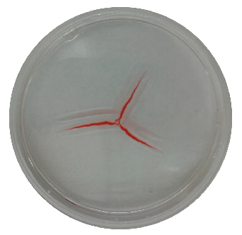
A liquid droplet resting on a soft gel substrate can deform that substrate to the point of material failure, whereby fractures develop on the gel surface that propagate outwards from the contact-line in a starburst pattern. In this paper, we characterize i) the initiation process in which the number of arms in the starburst is controlled by the ratio of surface tension contrast to the gel’s elastic modulus and ii) the propagation dynamics showing that once fractures are initiated they propagate with a universal power law . We develop a model for crack initiation by treating the gel as a linear elastic solid and computing the deformations within the substrate from the liquid/solid wetting forces. The elastic solution shows that both the location and magnitude of the wetting forces are critical in providing a quantitative prediction for the number of fractures and, hence, an interpretation of the initiation of capillary fractures. This solution also reveals that the depth of the gel is an important factor in the fracture process, as it can help mitigate large surface tractions; this finding is confirmed with experiments. We then develop a model for crack propagation by considering the transport of an inviscid fluid into the fracture tip of an incompressible material, and find that a simple energy-conservation argument can explain the observed material-independent power law. We compare predictions for both linear elastic and neo-Hookean solids finding that the latter better explains the observed exponent.
I Introduction
The interaction of soft substrates with fluid interfaces is common to many biological, medical, and industrial processes. For this reason, the field of elastocapillarity Roman2010 , in which one studies how surface tension forces couple to the deformations of elastic substrates, has been the subject of much recent attention. Even the most basic characterization of the wetting forces at the three-phase contact-line remains in dispute, especially for soft viscoelastic materials kajiya13 that have both liquid and solid properties. For such materials, the Young-Dupré law for a liquid wetting a hard solid, Neumann’s law for a liquid wetting another liquid, or some hybrid thereof may apply Snoeijer ; Weijs2013 . Theoretical efforts have been made to bridge the gap between the hard solid and liquid regime, such as introducing the concept of solid surface tension jerison11 ; style12 . Alternative methods employ computational approaches such as density functional theory (DFT) Das2011 and molecular dynamic (MD) simulations Weijs2013 to gain a more thorough understanding of the wetting forces acting at the contact-line.
In general, the elastic resistance must be comparable in magnitude to the surface tension forces applied to the elastic medium for many elastocapillary phenomenon. The elastocapillary number is a typical measure of the relative importance of capillarity to elasticity. Here is the surface tension, the elastic modulus and a characteristic length scale. In experiments, it is typically easiest to adjust , as seen in the wrinkling of elastic sheets huang07 ; vella10 ; Davidovitch2011 , capillary origami jung09 and buckling of elastic fibers evans13 . However, it is also possible to use a gel as the solid phase Mora2006 ; daniels07 ; jerison11 ; kajiya13 , which permits to be tuned over several orders of magnitude.
| () | () |
|---|---|
 |
 |
We focus our attention on recent experiments in which surfactant-laden fluid droplets are applied to soft gel substrates (daniels07, ; spandagos12a, ; spandagos12b, ), as shown in Figure 1. In these experiments, a partially-wetting liquid spreading on an agarose or gelatin substrate can produce capillary fractures that originate at the contact-line and propagate outwards in a starburst pattern. It is convenient to divide the fracture process into three phases: i) initiation, ii) nucleation and iii) propagation. The initiation phase sets a critical wavenumber through the elastic deformation field that controls the number of arms within the starburst fracture. In previous experiments, the number of arms has been shown to be controlled by the ratio of surface tension contrast to the gel’s elastic modulus (daniels07, ). The nucleation process in soft materials such as agarose gel is not deterministic, rather thermal fluctuations begin the fracture dynamics after some finite time delay (bonn, ; Wang2012a, ). Once the cracks are nucleated, they fill with fluid from the droplet and grow with a universal power-law which does not scale with any material parameters(daniels07, ). Intriguingly, even the application of a super-spreading surfactant (Silwet 77) does not increase the exponent (spandagos12a, ; spandagos12b, ). In this paper, we analyze the initiation and propagation processes separately.
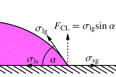
To study problems coupling elasticity to capillarity, it is helpful to put the typical length scales involved with such deformations into perspective. For a liquid on a hard substrate, the wetting properties are defined by the Young-Dupré equation young ; dupre ,
| (1) |
which relates the liquid/gas , liquid/solid and solid/gas surface tensions to the static contact-angle . Figure 2 illustrates the interpretation of the Young-Dupré relationship as a horizontal force balance. Note that this formulation also leads to an imbalance of vertical forces with magnitude . For a soft substrate with elastic modulus , this force gives rise to deformations of size , more commonly referred to as the elastocapillary length. For example, water ( mN/m) wetting a glass substrate ( GPa) yields a characteristic deformation m, justifying the neglect of the unbalanced force. Recently, Jerison et al. have used fluorescence confocal microscopy to show that water droplets interacting with silicone gel ( kPa) yield micron-size substrate deformations m jerison11 ; style12 . For the capillary fracture experiments shown in Figure 1, which involve ultra-soft agaraose substrate ( Pa), the elastocapillary length corresponds to m (millimetric) deformations. Given the size of such deformations, it is therefore unsurprising that fractures occur.
| () |
 |
| () |
 |
We begin this paper by defining the equations governing the deformation of an elastic substrate loaded by a partially-wetting liquid droplet with a corrugated contact-line in §II. We solve the governing equations to show there is a critical disturbance with wavenumber that generates the largest elastic response, as measured by the tangential displacement, which we associate with the number of arms in a starburst fracture. The solution illustrates that the location of the unbalanced contact-line force is an important parameter in wavenumber selection. This dependence is quantitatively confirmed in experiments where the wetting conditions are fixed and the volume is varied, validating our interpretation of the initiation of capillary fractures. In addition, the depth of the gel can play a similar role in the initiation process, which we confirm with experiments. Section III briefly discusses the nucleation process. In §IV, we model the crack propagation dynamics by considering the transport of an inviscid fluid into the crack tip of an elastic solid, subject to energy conservation (Bernoulli’s law). While it is reasonable to assume that the solid behaves as a linear elastic material for the deformation phase, this assumption is almost certainly violated once a fracture has been nucleated. Therefore, we develop a model for the propagation dynamics which allows for considering either a i) linear elastic or ii) neo-Hookean solid. Both elastic models for the solid predict power law growth, but the exponent from the neo-Hookean model matches the observed power law behavior . The predicted exponent and pre-factor do not depend on any of the material parameters, consistent with experimental observations daniels07 ; spandagos12a ; spandagos12b . We conclude with some remarks in §V regarding capillary fracture in soft materials.
II Crack initiation
Consider a liquid droplet, contained at its free surface by the liquid-gas surface tension and resting on a linear elastic substrate of thickness , which is characterized by an elastic modulus and Poisson ratio , as shown in Figure 3(). This partially-wetting liquid interacts with the solid through the capillary pressure uniformly distributed over the liquid/solid contact area and the unbalanced (vertical) contact-line force applied at the contact-line radius (see Figure 3 ()). Here we note that an alternative model of wetting which, in addition to the capillary pressure and vertical contact-line force, also includes a horizontal contact-line force directed into the liquid phase has recently been put forth Snoeijer ; Weijs2013 . For the purposes of this paper, however, we restrict ourselves to a model of wetting that includes the capillary pressure and vertical contact-line force. The extent to which the liquid partially wets the solid is controlled by the surface tension contrast , or equivalently the static contact-angle , defined by the Young-Dupré equation (Equation 1). We characterize the elastic response in the substrate due to both the capillary pressure and the contact-line force associated with a corrugated contact-line.
II.1 Field equations
We begin by introducing the displacement field ,
| (2) |
in cylindrical coordinates (), which satisfies the governing elastostatic Navier equations,
| (3) |
The strain field is defined as
| (4) |
while the stress field for this linear elastic solid is given by
| (5) |
II.2 Boundary conditions
We assume the elastic substrate is pinned to a rigid support at by enforcing a zero displacement boundary condition there,
| (6) |
In experiments this support corresponds to the bottom of the dish holding the substrate material. Similarly, we specify the surface tractions on the free surface ,
| (7) |
where is the surface Laplacian and is the applied force associated with the liquid/solid (wetting) interactions. Here we introduce the solid surface tension for rigor as well as to regularize the singularity associated with applying a delta function force to the surface of an elastic medium, as discussed in style12 .
We now develop a model for the forces associated with the wetting of a liquid droplet on a soft elastic substrate. First, we note that the surface of our gel substrate is heterogeneous so that the location of the contact-line generally takes the form (in fact, corrugations are typically present even for ideal solid or liquid substrates). For a liquid droplet held by uniform surface tension , the wetting forces associated with this configuration are given by
| (8) |
where and are the Heaviside and delta functions, respectively (see Figure 3 ()). Here the capillary pressure is uniformly distributed over the liquid/solid surface area, whereas the unbalanced contact-line force is applied as a point load at the contact-line. Note the orientation of the applied forces; the capillary pressure compresses the substrate, while the contact-line force tends to pull the substrate upwards. As we are interested in identifying a critical wavenumber to associate with the number of arms in the starburst fracture, we assume the contact-line radius has the following representation , where is the azimuthal wavenumber. We then apply this functional form for to eqn. (8) and expand for small to show the non-uniform part of the wetting force is given by
| (9) |
Equations (3, 6, 7 & 9) define a boundary value problem governing the elastic deformations of a substrate interacting with a liquid droplet with a corrugated contact-line.
II.3 Displacement potential
We simplify the elastostatic governing equations (3) by introducing the displacement potentials defined such that
| (10) |
with
| (11) |
Substituting (10) into the coupled system of differential equations (3) delivers a set of uncoupled equations for ,
| (12) |
The displacement (6) and traction (7) boundary conditions can similarly be written in terms of the potential functions .
II.4 Fourier-Hankel expansion
We seek solutions to (12) for the potential functions using Fourier-Hankel transforms. To begin, we assume has the following Fourier decomposition,
| (13) |
Next, the Hankel transform is applied to each Fourier component to yield
| (14) |
where is the Bessel function of the first kind and is the radial wavenumber. One applies the inverse Hankel transform
| (15) |
to recover , and equivalently .
II.5 Reduced equations
The following dimensionless variables are introduced:
| (16) |
with lengths scaled by the thickness of the elastic substrate and elastic deformations by the elastocapillary length . In the derivation that follows, we drop the hats for notational simplicity. Substituting the expansions (13),(14) into (12) gives reduced field equations for ,
| (17) |
The following conditions are enforced on the rigid support ,
| (18) |
while on the free surface we require
| (19) |
with
| (20) |
The following dimensionless groups arise naturally from this choice of scaling,
| (21) |
Here is the solid elastocapillary number and is the aspect ratio or dimensionless contact-line radius. The solution to (17)–(19) is given by
| (22) |
where
| (23) |
II.6 Results
We compute the elastic response in the substrate for a fixed wavenumber , consistent with the boundary conditions (6,7). That is, we assume that a corrugated contact-line, with wavenumber , gives rise to surface tractions (7) that generate displacements , and equivalently stresses and strains , within the gel substrate. We seek to develop a criteria based upon our solution for the elastic fields, that will yield a prediction for the critical wavenumber that is consistent with the number of fractures seen in experiments. This value can then be compared with the number of fracture arms observed in experiments.
For the problem considered here, there are independent components of the displacement field, for the strain field and for the stress field, all of which vary in the two-dimensional space (domain) in cylindrical coordinates. We utilize several experimental observations to formulate our criteria. Firstly, we restrict our criteria to components of the displacement field, as failure in agarose gels typically correspond to disentanglement of the helices within the network of cross-linked, polymeric bonds. Secondly, experiments reveal that fractures are typically of the Mode (opening) variety daniels07 . These observations suggest our ‘failure criteria’ should correlate with the maximum value of the component of the displacement field. Accordingly, we compute the displacement for fixed values of the parameters . We simplify our problem further by setting the Poisson ratio , which is a reasonable assumption for incompressible agarose gels. In this case, the elastic modulus is then simply related to the shear modulus through the relationship .
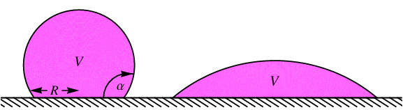
The connection between the problem considered here and the experiment in question is somewhat subtle. For a given set of experimental conditions, one defines the liquid/solid (wetting) interactions by the choice of fluid, which sets (equivalently) either the surface tension contrast or the static contact-angle through the relation . Hence, the unbalanced contact-line force could also be written in terms of the surface tension contrast , if desired. Note that increasing the surface tension contrast is equivalent to decreasing the static contact-angle and consequently the magnitude of the contact-line force . Naively, one might think that fixing the droplet volume , as is typically done in experiments, would set the contact-line radius and hence the location of the contact-line force. However, is also a function of the the wetting conditions. For a spherical-cap droplet, this relationship is given by
| (24) |
as shown schematically in Figure 4. The difficulty is that adjusting for fixed , as is typically done in experiments, changes both and . The benefit is that it is possible to explore a wide range of contact-line radii by changing either or .
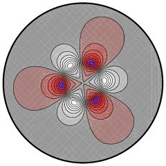
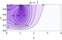
To summarize, both the magnitude and location of the contact-line force implicitly depend upon the wetting conditions through the static contact-angle . Henceforth, we restrict ourselves to variations in , and equivalently . To isolate the critical disturbance , we fix the parameters and compute the displacement everywhere in the plane for each wavenumber searching for its maximum value, our failure criteria. As such, Figure 5 shows that the location of maximum displacement occurs directly beneath the contact-line at some finite depth below the gel surface . For this set of parameters , the critical disturbance is the mode, as it generates the greatest elastic response in the gel substrate (see Figure 6()).
| () | () | () |
|---|---|---|
 |
 |
 |
| () | () | () |
|---|---|---|
 |
 |
 |
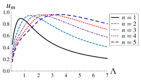
We systematically study the parametric dependence of the critical disturbance upon the parameters utilizing the observation that the maximum displacement occurs directly beneath the contact-line. Figure 6 plots the displacement as a function of depth for various wavenumber disturbances to demonstrate that the critical disturbance depends strongly upon the contact-line radius . For example, Figure 6() shows that the mode is the critical disturbance for , whereas the mode is the most dangerous for , as shown in Figure 6(). In general, one observes from Figure 6 that the critical disturbance is the one that penetrates deepest into the elastic layer.
| () | () |
|---|---|
 |
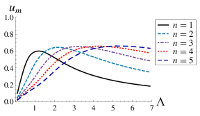 |
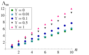
For fixed wavenumber , we compute the maximum displacement through the depth of the elastic layer as a function of contact-line radius , as shown in Figure 7 for two different solid elastocapillary numbers () and () . For a given , there is a wavenumber that generates the largest elastic response, as measured by . Here one should note the tight spacing between curves in Figure 7, which perhaps explains why a range of wavenumbers are observed for a given experiment. More specifically, slight variations in due to a number of experimental factors can alter the expected wavenumber. Figure 8 plots the critical wavenumber against contact-line radius . Here we note that our theoretical prediction is consistent with experiments for fixed volume droplets daniels07 , which indicate the number of arms in the starburst fracture increases with increasing (decreasing) (), and equivalently increasing . In fact, Figure 9 shows good quantitative agreement between theory and experiments for fixed volume droplets. For the comparison, we have estimated experimental values using reasonable values of the liquid/solid surface tension to compute the contact-angle and equivalently .
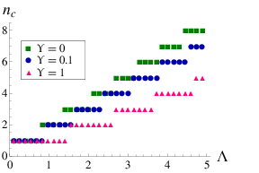
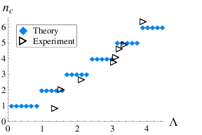
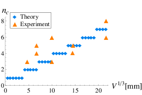
Our model indicates that it is the location of the contact-line force that selects the critical wavenumber , as opposed to the magnitude of that force. In fact, the magnitude of the contact-line force, , decreases with increasing (decreasing) (), which is somewhat paradoxical considering that naively one expects less fractures for smaller forces. Our interpretation of the fracture mechanism is confirmed in Figure 10, which plots the experimentally-observed wavenumber against for fixed compared to the model’s prediction. We observe quantitative agreement between the model and experiments.
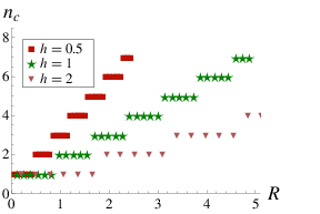
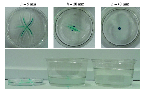
Our computations reveal that the thickness of the gel substrate is also a critical parameter in determining the critical wavenumber, as couples two length scales, and . Figure 11 plots the critical wavenumber against the unscaled contact-line radius for various values of substrate height . As shown, the critical wavenumber increases (decreases) with decreasing (increasing) substrate height . This result, in effect, implies that large substrate heights are better able to mitigate the imposed surface tractions. Experiments conducted on substrates of two different thicknesses confirm this prediction. Figures 11 () & () are two experiments both conducted on substrates with elastic modulus Pa, but differing thickness () cm, () cm and surface tension contrast () mN/m, () mN/m, whose critical wavenumber is given by () and () , respectively. If the thickness of the elastic layer were unimportant, then one would expect () to produce more arms than (), because of the greater surface tension contrast. We observe the opposite, demonstrating that the thickness of the elastic layer is more important in identifying the critical wavenumber.
| () |
 |
| () |
 |
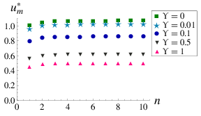
Lastly, we note that for a given wavenumber there is a preferred contact-line radius that generates the largest elastic response , as shown in Figure 7. In Figure 12, we plot the () location and () value of the maximal disturbance as a function of wavenumber , as it depends upon the solid elastocapillary number . First, we note that the location is an increasing function of both wavenumber and solid elastocapillary number . In contrast, Figure 12 () shows that is a slightly increasing function of that plateaus for large wavenumber. More specifically, the increase in is particularly evident in Figure 7 () when comparing the to the disturbances. This implies that if, in experiment, one observes fractures, then it is always possible to adjust the droplet volume to generate fractures. The converse is not necessarily true. Finally, we show that decreases with reflecting the energetic penalty for flexure associated with the solid surface tension. In the large- regime, the gel substrate behaves more like a liquid than a solid. We note that this result is not inconsistent with larger deformations for weaker substrates, as the real displacements are scaled with the elastocapillary length (16). That is, decreasing the elastic modulus increases the solid elastocapillary number , but also the elastocapillary length and, thus, the real displacements.
| () |
 |
| () |
 |
We end this section with a comment on the failure criteria. The results presented in this section have assumed that the substrate is always weak enough to generate deformations that exceed the failure threshold for agar gel. As such, we have focused our study on identifying a critical wavenumber and not the failure threshold. Additional experiments would be needed to extract such information.
III Crack nucleation
The model developed above captures the central feature required to generate a starburst with a particular number of arms: a critical wavenumber for which the tangential displacement is maximal. In experiments, we observe that for a given set of experimental conditions, a narrow range of wavenumbers are selected; this is not surprising given that values of can have a maximum displacement similar to . However, the failure criteria does not provide a failure mechanism. In physical gels such as agar or gelatin, the stiffness of the material is provided by a network of entangled polymers (Goldbart1989a, ). Under strain, these polymers are stretched further away from equilibrium, although not necessarily to the point of failure. Because polymers are subject to thermal fluctuations, even a sub-critical strain can be triggered by a sufficiently large thermal fluctuation. This is the mechanism behind delayed fracture, whereby there is an exponential distribution of waiting times (indicating a Poisson process) before which a strained material fractures. This has been directly observed in both stiffer gelatin rods ( kPa) bonn and in vibration-controlled experiments in this system.
IV Crack propagation
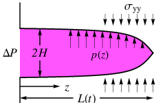
Once a fracture is initiated, fluid begins to flow into the crack tip and the crack propagates outward (away from the central droplet) until the reservoir of fluid is exhausted. We develop a two-dimensional model for the asymptotic propagation of a Mode I fracture driven by a pressure head . A schematic is shown in Figure 13. To begin, we consider an incipient crack of length , filled with an inviscid fluid of density , propagating into an elastic solid.In this section, we model the solid as either i) a linear elastic material or ii) an incompressible neo-Hookean material, as is typically used for polymeric gels, and contrast the computed propagation rates.
We assume the capillary pressure head at the fluid reservoir is greater than the elastic stress in the solid in front of that reservoir, so as to drive fluid into the crack tip. The flow of this inviscid fluid is governed by Bernoulli’s law,
| (25) |
and, hence, driven by the gradient in fluid pressure , which is related to the elastic stress induced by deformations of the crack surface. Here we assume there is no ambient stress field in the elastic solid, or the substrate is not pre-stressed. The localized stress (pressure) field near the crack tip of a linear elastic solid has the well-known asymptotic form pook ,
| (26) |
For an incompressible neo-Hookean solid, the asymptotic stress field is given by stephenson82 ; krishnan09 ,
| (27) |
Here and are stress intensity factors for a linear elastic and incompressible neo-Hookean solid, respectively. In general, is a function of the crack geometry and far-field loading conditions, but we may simplify our model by utilizing several experimental observations.
Recent experiments have demonstrated self-healing behavior of fluid-filled cracks in soft substrates spandagos12a ; spandagos12b . This observation is characteristic of stable, or transport-limited, crack growth. That is, the speed of crack growth is limited by the extent to which the fluid can be supplied (transported) to the crack tip. For reference, unstable crack growth would be controlled by the speed of an elastic wave in the solid, a characteristic which is not observed experimentally. Hereafter, we assume the crack propagates in the marginal state , where is the fracture toughness, consistent with stable crack growth.
We apply Bernoulli’s law (25) using the crack tip (state 1) and a point upstream (state 2) to derive an equation relating the crack-tip velocity to the pressure gradient in the linear elastic solid (26):
| (28) |
whose solution gives
| (29) |
This predicts a characteristic exponent of for the growth of the arm. A similar relationship is derived for an incompressible neo-Hookean solid by applying the respective stress field (27) instead:
| (30) |
For this system, the characteristic exponent is instead :
| (31) |
Note that both constitutive models predict power law behavior, but the neo-Hookean model is able to reproduce the universal exponent observed experimentally daniels07 . We attribute this result to the observation that the gel substrate is incompressible and that the large scale deformation of the soft solid are more aptly described by the nonlinear neo-Hookean constitutive law.
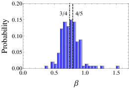
Because the gels are spatially-heterogeneous, cracks nucleate with different widths and propagate at varying rates. We fit the length of each fracture arm to the form and examine the distribution of values observed. No systematic variation with material parameters was found for the values of , but the width of the crack determines the pre-factor (daniels07, ). For this same data set of individual arms, we find that (standard error). The full probability distribution is show in Figure 14, which allows for comparison to the (neo-Hookean) and (linear elastic) constitutive models.
V Discussion
We have analyzed the deformations of a soft elastic substrate induced by the liquid/solid interactions with a liquid droplet, as well as the propagation of a fluid-filled crack in a soft elastic medium. The deformations associated with a corrugated contact-line yield a critical disturbance with wavenumber that generates the largest elastic response within the substrate. We quantify the response with the tangential displacement, a failure criteria which we correlate with the initiation of a starburst fracture (see Figure 1). Computations reveal that the location of the unbalanced contact-line force is the most important parameter in wavenumber selection. Our theoretical predictions compare favorably to i) previously-reported experiments with fixed volume droplets daniels07 and ii) experiments where the contact-angle is fixed and the droplet volume is varied, thereby confirming our interpretation of the initiation process. Our model also predicts that the substrate thickness is also an important parameter in wavenumber selection, an observation which we see in experiments. For the crack propagation problem, we develop a model by considering the transport of an inviscid fluid into the crack tip of either a linear elastic or incompressible neo-Hookean solid. While both elastic models yield power law growth, the neo-Hookean model predicts the crack length grows with universal exponent and does not scale with any material parameters, consistent with experimental observations daniels07 ; spandagos12a ; spandagos12b .
Studies on fracture necessarily take place on materials which are strong enough to resist fracture until the point when the measurement is made. However, many biological materials are soft enough that conventional fracture measurements are not possible because the material is too weak to support its own weight. The present study suggests that by depositing a droplet of known size and wettability, it could be possible to use starburst fractures to measure the fracture toughness of very soft materials so long as they remain fully supported by the dish. Furthermore, because the growth rate of fractures is sensitive to whether or not the material is linear-elastic, this could also provide a new method for materials characterization.
Acknowledgements
The authors are grateful for support from the National Science Foundation under grant number DMS-0968258, as well as NC State’s Undergraduate Research Office, to Michael Shearer for valuable discussions, and to Mark Schillaci for preliminary experiments useful in formulating the model.
References
- (1) B Roman and J Bico. Elasto-capillarity: deforming an elastic structure with a liquid droplet. Journal of Physics: Condensed Matter, 22(49):493101, November 2010.
- (2) Tadashi Kajiya, Adrian Daerr, Tetsuharu Narita, Laurent Royon, Francois Lequeux, and Laurent Limat. Advancing liquid contact line on visco-elastic gel substrates: stick-slip vs. continuous motions. Soft Matter, 9:454–461, 2013.
- (3) Antonin Marchand, Siddhartha Das, Jacco H. Snoeijer, and Bruno Andreotti. Contact angles on a soft solid: from Young’s Law to Neumann’s Law. Phys. Rev. Lett., 109:236101, Dec 2012.
- (4) Joost H Weijs, Bruno Andreotti, and Jacco H Snoeijer. Elasto-capillarity at the nanoscale : on the coupling between elasticity and surface energy in soft solids. Soft Matter, 9:8494–8503, 2013.
- (5) Elizabeth R. Jerison, Ye Xu, Larry A. Wilen, and Eric R. Dufresne. Deformation of an elastic substrate by a three-phase contact line. Phys. Rev. Lett., 106:186103, May 2011.
- (6) Robert W. Style and Eric R. Dufresne. Static wetting on deformable substrates, from liquids to soft solids. Soft Matter, 8:7177–7184, 2012.
- (7) Siddhartha Das, Antonin Marchand, Bruno Andreotti, and Jacco H. Snoeijer. Elastic deformation due to tangential capillary forces. Phys. Fluids, 23(7):072006, 2011.
- (8) Jiangshui Huang, Megan Juszkiewicz, Wim H. de Jeu, Enrique Cerda, Todd Emrick, Narayanan Menon, and Thomas P. Russell. Capillary wrinkling of floating thin polymer films. Science, 317(5838):650–653, 2007.
- (9) D. Vella, M. Adda-Bedia, and E. Cerda. Capillary wrinkling of elastic membranes. Soft Matter, 6:5778–5782, 2010.
- (10) Benny Davidovitch, Robert D Schroll, Dominic Vella, Mokhtar Adda-Bedia, and Enrique Cerda. Prototypical model for tensional wrinkling in thin sheets. Proceedings of the National Academy of Sciences, 108(45), October 2011.
- (11) Sunghwan Jung, Pedro M. Reis, Jillian James, Christophe Clanet, and John W. M. Bush. Capillary origami in nature. Phys. Fluids, 21(9):091110, 2009.
- (12) Arthur A. Evans, Saverio E. Spagnolie, Denis Bartolo, and Eric Lauga. Elastocapillary self-folding: buckling, wrinkling, and collapse of floating filaments. Soft Matter, 9:1711–1720, 2013.
- (13) T Mora and a Boudaoud. Buckling of swelling gels. The European Physical Journal E: Soft matter, 20(2):119–24, June 2006.
- (14) Karen E. Daniels, Shomeek Mukhopadhyay, Paul J. Houseworth, and Robert P. Behringer. Instabilities in droplets spreading on gels. Phys. Rev. Letters, 99:124501, 2007.
- (15) Constantinos Spandagos, Thomas B. Goudoulas, Paul F. Luckham, and Omar K. Matar. Surface tension-induced gel fracture. part 1. fracture of agar gels. Langmuir, 28(18):7197–7211, 2012.
- (16) Constantinos Spandagos, Thomas B. Goudoulas, Paul F. Luckham, and Omar K. Matar. Surface tension-induced gel fracture. part 2. fracture of gelatin gels. Langmuir, 28(21):8017–8025, 2012.
- (17) D Bonn, H Kellay, M Prochnow, K Ben-Djemiaa, and J Meunier. Delayed Fracture Of An Inhomogeneous Soft Solid. Science, 280(5361):265–267, Apr 1998.
- (18) Xiao Wang and Wei Hong. Delayed fracture in gels. Soft Matter, 2012.
- (19) T. Young. An essay on the cohesion of fluids. Phil. Trans. R. Soc. London, 95:65–87, 1805.
- (20) A. Dupré. Théorie Méchanique de La Chaleur. Paris, Gauthier-Villars, Paris, France, 1869.
- (21) Paul Goldbart and Nigel Goldenfeld. Microscopic theory for cross-linked macromolecules. I. Broken symmetry, rigidity, and topology. Physical Review A, 39(3):1402–1411, feb 1989.
- (22) L.P. Pook. Linear Elastic Fracture Mechanics for Engineers: Theory and Applications. WIT Press, Boston, MA, 2000.
- (23) R.A. Stephenson. The equilibrium field near the tip of a crack for finite plane strain of incompressible elastic materials. J. Elasticity, 2:65–99, 1982.
- (24) V.R. Krishnan and C.-Y. Hui. Finite strain stress fields near the tip of an interface crack between a soft incompressible elastic material and a rigid substrate. The European Physical Journal E, 29:61–72, 2009.