Realization of Morphing Logic Gates in a Repressilator with Quorum Sensing Feedback
Abstract
We demonstrate how a genetic ring oscillator network with quorum sensing feedback can operate as a robust logic gate. Specifically we show how a range of logic functions, namely AND/NAND, OR/NOR and XOR/XNOR, can be realized by the system, thus yielding a versatile unit that can morph between different logic operations. We further demonstrate the capacity of this system to yield complementary logic operations in parallel. Our results then indicate the computing potential of this biological system, and may lead to bio-inspired computing devices.
I Introduction
The operation of any computing device is necessarily a physical process, and this fundamentally determines the possibilities and limitations of the computing machine. A common thread in the history of computers is the exploitation and manipulation of different natural phenomena to obtain newer forms of computing paradigms computing . For instance, chaos computing chaogates , neurobiologically inspired computing, quantum computingquantum , and DNA computingdna all aim to utilize, at the basic level, some of the computational capabilities inherent in natural systems. In particular, larger understanding of biological systems has triggered the interesting question: what new directions do bio-systems offer for understanding and implementing computations?
The broad idea then, is to create machines that benefit from natural phenomena and utilize patterns inherent in systems to encode inputs and subsequently obtain a desired output. Different physical principles can yield logic outputs, for logic gates such as AND, OR, XOR, NOR and NAND which form the basis of the universal general-purpose computation. It is particularly interesting if systems of biological relevance can also yield logic outputs consistent with the truth tables of different logic functions benenson ; ando ; gene2 .
In this work we will explore the computational possibilities arising from the dynamics of a genetic network with quorum sensing feedback. Quorum sensing allows cells to sense their own density and to communicate with each other, giving the cells the ability to behave as a population instead of individually. The autoinduction of luminescence in the symbiotic marine bacterium Vibrio fischeri is perhaps the best characterized example of quorum sensing. Some other examples include sporulation and fruiting body formation by Myxococcus Xanthus and antibiotic production by several species of Streptomyces. The way quorum sensing is accomplished in cells is through diffusive exchange of auto-inducer molecules which participate in intercellular coupling and self feedback. At low cell density, the auto inducer is synthesized at basal levels and diffuses into the extracellular space and gets diluted. But as the cell density increases, the intracellular autoinducer concentration increases until it reaches a threshold beyond which it is produced auto-catalytically. This results in a dramatic increase of product concentrations, thus creating bi-stability between a high steady state and a low steady state dockery ; james .
Specifically, in this work we focus on an artificial genetic network known as the repressilator, with feedback of the kind that quorum sensing may provide to an isolated repressilator. A repressilator consists of a ring of three genes, products of which inhibit each other in cyclic order. The quorum sensing feedback stimulates the activity of a chosen gene providing competition between the inbitory and the stimulatory activities localized in that gene. In this work we attempt to use the varying concentrations of proteins in the repressilator, arising due to quorum sensing feedback, to realize different logic gates.
In the sections below we will first discuss the model of the repressilator genetic network with quorum sensing feedback, and present the change in dynamics of repressilator proteins with changing parameters of the quorum sensing feedback. We will then go on to use this dynamics to implement a range of logic functions, by appropriate input-output associations.
II Repressilator Genetic Network with Quorum sensing Feedback
We consider a basic genetic ring oscillator network in which three genes inhibit each other in unidirectional manner, and an additional quorum sensing feedback loop stimulates the activity of a chosen gene, providing competition between inhibitory and stimulatory activities localized in that gene. This system is known to yield behaviour ranging from limit cycles, to high and low stable steady states Hellen .
In the model, 3 genes in a cyclic loop forms mRNA () and proteins (). The three genes inhibit each other, where one gene is inhibited by the preceding gene. Quorum sensing feedback acts between gene and , where stimulates the production of by quorum sensing along with an inhibitory action. The model can be reduced to fast mRNA kinetics, where is assumed to be in a steady state with their respective proteins (), leading to .
The equations describing the dynamics of this system then are:
| (1) | |||||
| (2) | |||||
| (3) | |||||
| (4) |
Here denotes the concentration of the auto-inducer AI.
The relevant parameters in this system are the ratio of protein decay rate to mRNA decay rate , maximum transcription rate in the absence of an inhibitor , Hill co-efficient for inhibition , diffusion co-efficient depending on the permeability of the membrane to auto-inducer molecule , the rate of auto-inducer decay to mRNA decay rate , rate of auto-inducer production , and most importantly, the co-efficient for the production of protein due to auto-inducer and the concentration of auto-inducer in external medium responsible for the quorum sensing feedback.
In our simulations we fix the parameters at realistic values Hellen : , ; ; , and (relevant to slow protein kinetics). We vary the parameters that determine the strength of quorum sensing, namely and .
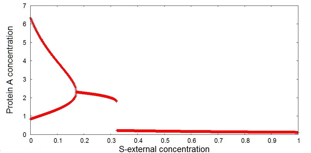
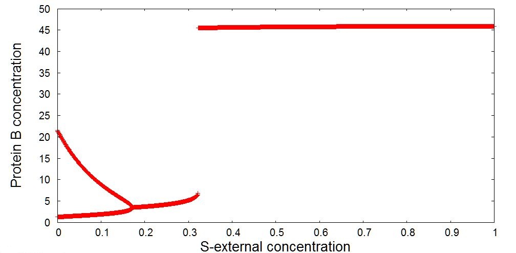
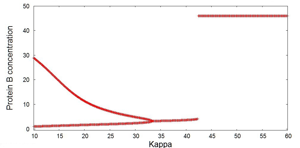
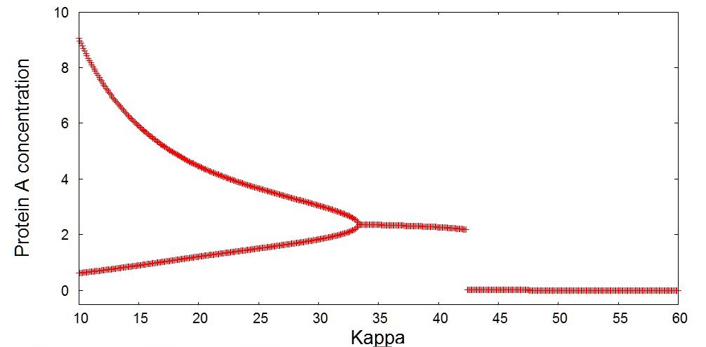
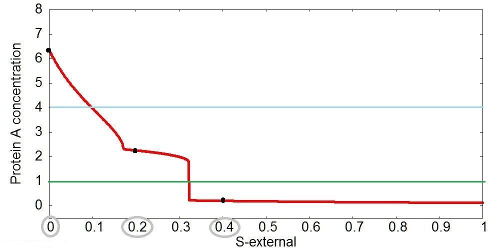
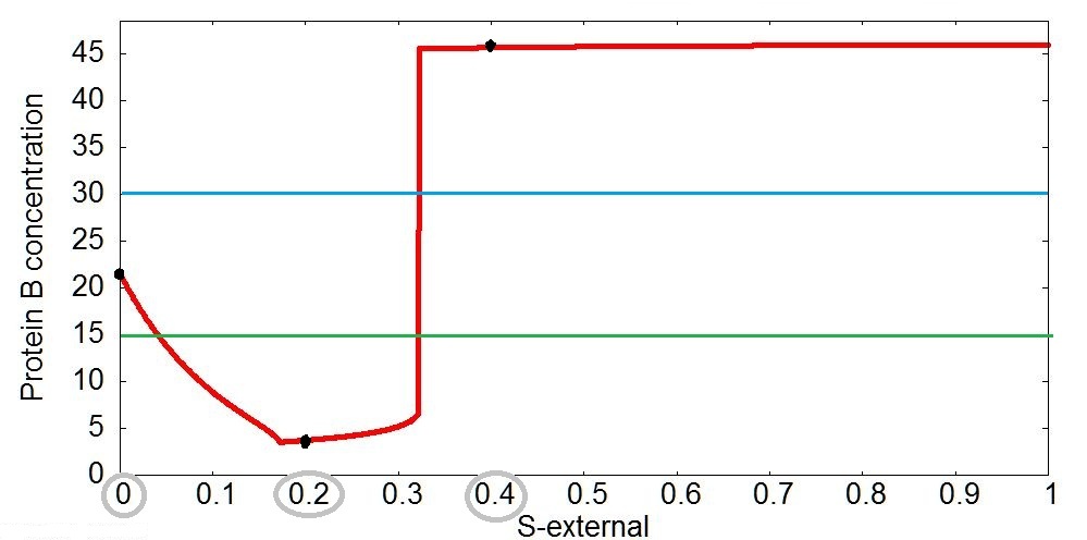
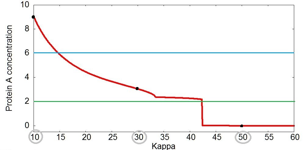
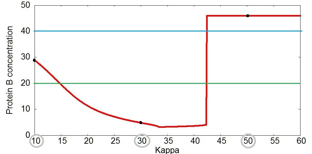
On taking different values of parameters and , the strength of quorum sensing changes, and hence the qualitative nature of the dynamics changes. This is clearly evident from the bifurcation analysis of the concentrations of protein and with respect to parameters and displayed in Figs. 1-2, which shows the change in dynamics from limt cycles to stable steady states as the external concentration of auto-inducer increases. There is also a sudden switch in the value of the steady state after a critical value of and .
III Realization of Logic Gates
Now, in order to utilize this system to realize a logic gate we need to propose an appropriate input-output mapping, namely, we must first suggest how inputs and outputs are encoded. The task at hand then, is to ensure that this input and output encoding consistently yields the correct input-output association corresponding to different logic functions, as displayed in the truth table (Table I).
Specifically, here we will implement a series of logic gates, such as
AND/NAND, OR/NOR and XOR/XNOR, using the change in dynamics of protein
and . Further we will obtain logic operations in parallel by
simultaneous measurement of the concentrations of these two proteins.
Encoding Logic Inputs:
Consider the inputs to be encoded by , namely the concentration of auto-inducer in external medium, which is responsible for the quorum sensing feedback.
We propose that the two inputs where and encode the two logic inputs as follows:
-
(i)
When logic input is , ;
-
(ii)
When logic input is , ;
So the pair of inputs lead to the following three distinct conditions:
-
(i)
for input set
-
(ii)
for input set
-
(iii)
for input set
Encoding Logic Output:
We consider the maximum protein concentration as an indicator of the output of the system. Specifically we consider the maximum concentrations of proteins and , denoted by and respectively. This gives us the ability to obtain two outputs from the system in parallel.
Now a prescribed output determination threshold, and , leads to the mapping of the concentration to a logic output, as folllows:
For protein :
-
(i)
If , then the Logic Output is
-
(ii)
If , then the Logic Output is
And for protein :
-
(i)
If , then the Logic Output is
-
(ii)
If , then the Logic Output is
One can obtain the complementary gates by exchanging the output determination criterion. Namely:
For protein :
-
(i)
If , then the Logic Output is
-
(ii)
If , then the Logic Output is
And for protein :
-
(i)
If , then the Logic Output is
-
(ii)
If , then the Logic Output is
Controlling the nature of the Logic Function:
We can control the type of logic operation obtained by simply changing the output determination threshold. Namely, we can obtain AND/NAND, OR/NOR or XOR/XNOR input-output mappings by considering different and .
For instance, for realizing the fundamental NAND Logic gate (see Truth table I), we have the binary logic output determined by the threshold level . Namely, if the maximum concentration of protein , is greater than , then the Logic Output is , and if , then Logic Output is . This is clearly evident in Fig. 3 and Table 2.
In order to change the logic function from the fundamental NAND gate to the funademental NOR gate, we simply have to change the prescribed output determination threshold. Specifically, the system yields NOR logic when the output determination threshold is .
Similarly, using different output determination thresholds for protein concentration , we can obtain AND and XNOR logic operations. This is clearly evident through Fig. 4 and Table 3. Again note that the complementary logic functions NAND and XOR are implemented by a simple toggle of the logic output determination condition.
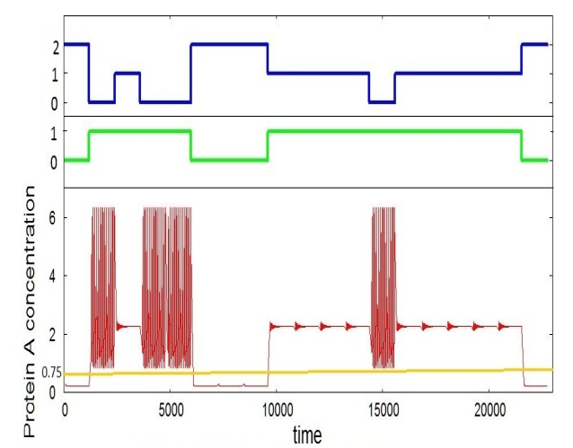
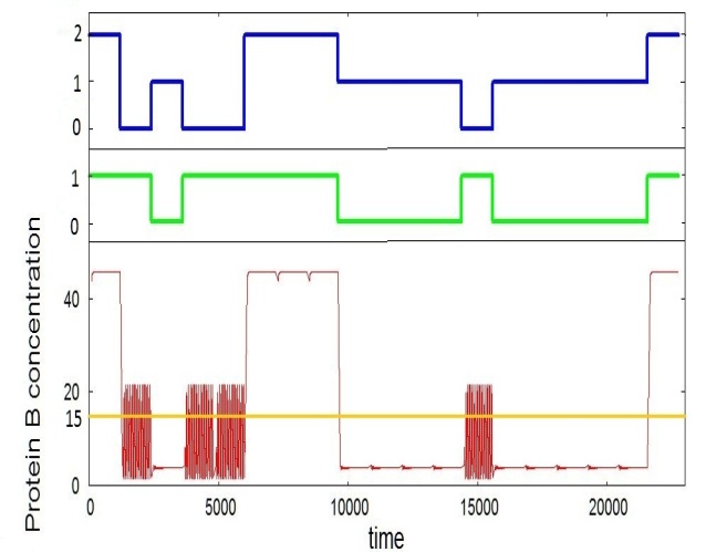
So we can obtain any combination of AND/NAND/OR/NOR in parallel with AND/NAND/XOR/XNOR logic through the two protein concentrations for the same pair of inputs. In Fig. 5, the time series plots for Protein and exhibits the simultaneous realization of NAND and XNOR gates respectively, for a representative random stream of input values. Clearly, this same system can yield XOR and AND in parallel by the alternate output association, namely a logic output is obtained when the proteins and are below output threshold and respectively, and otherwise. In fact, the combination of AND and XOR in parallel is particularly useful, as it forms the basis of the ubiquitous bit-by-bit addition.
Alternately, the logic operation may also be changed by a constant
shift in input encoding, namely ,
where different values of yield different logic
functions. For instance, using protein for output determination,
and keeping level fixed at , yields XNOR,
and yields NAND. Similarly, using protein for
output determination, with , yields NAND, and
yields NOR.
Using activation rate parameter to encode Logic Inputs:
We now consider an alternate input encoding, with the logic inputs determining . Here is held fixed at , and varying yields different protein concentrations, which leads to different outputs (see Figs. 6-7).
Specifically, let be determined by the logic inputs and as follows:
with when logic input is , and when logic input is .
Taking a base value of , we have:
-
(i)
when input set () is
-
(ii)
when input set () is
-
(iii)
when input set () is
The binary Logic Output is obtained from the maximum concentration of proteins and , as before. Namely, we determine the logic output through a threshold: if , then logic output is , and if , then logic output is .
As before, the nature of the logic function obtained can be controlled by the output determination threshold for the proteins and . When we obtain NAND logic and for we obtain the fundamental NOR operation. Similarly, when we obtain AND and for we obtain XNOR. Representative values are displayed in Tables 4 and 5.
Hence, XNOR/XOR/AND/NAND and NAND/AND/NOR/OR gates can be realized in parallel for the same set of inputs. Namely, by setting the appropriate output determination condition, the protein concentrations can yield any of the logic functions XNOR/XOR/AND/NAND and NAND/AND/NOR/OR independently and simultaneously.
IV Conclusions
In summary, we have demonstrated how a genetic ring oscillator network with quorum sensing feedback can operate as a robust logic gate. We use the concentration of auto-inducer in external medium , and alternatively an activation rate parameter (cf. Eqn. 1), to encode logic inputs. Both these quantities regulate the strength of the quorum sensing feedback. The concentrations of proteins and determine the logic outputs. This input-output association yields a range of logic functions, namely AND/NAND, OR/NOR and XOR/XNOR. So the system can act as a versatile unit that can morph between different logic operations. We further demonstrated the capacity of this system to yield different logic operations simultaneously through the two proteins and .
These observations may provide an understanding of the computational
capacity of systems with quorum sensing feedback. It also may have
potential relevance in the design of biological gates, with the
ability to flexibly reconfigure logic operations, and implement logic
operations in parallel. Further, since electronic analogs of such
systems have already been implemented Hellen , our results may
readily lead to bio-inspired computing devices.
References
- (1) J. P. Crutchfield, W. L. Ditto, and S. Sinha, Introduction to Focus Issue: Intrinsic and Designed Computation: Information Processing in Dynamical Systems – Beyond the Digital Hegemony, Chaos 20 037101 (2010)
- (2) S. Sinha and W.L. Ditto, Phys. Rev. Lett. 81 (1998) 2156; K. Murali, S. Sinha, W.L. Ditto, A.R. Bulsara, Phys. Rev. Lett. 102 (2009) 104101; W. L. Ditto, A. Miliotis, K. Murali, S. Sinha, and M. L. Spano, Chaos 20 (2010) 037107
- (3) A. Steane (1998) Rep. Prog. Phys. 61 117
- (4) DNA Computing: New Computing Paradigms, G. Paun, G. Rozenberg and A. Salomaa, Springer (Berlin and New York) 1998
- (5) Y. Benenson, Science 340 (2013) 554
- (6) Ando, H., Sinha, S., Storni, S., and Aihara, K.: Synthetic gene networks as potential flexible parallel logic gates. Europhys. Letts., 93 (2011) 50001.
- (7) E. H. Hellen, S. K. Dana, J. Kurths, E. Kehler, S. Sinha, Noise-aided Logic in an Electronic Analog of Synthetic Genetic Networks, PLoS One (2013) doi:10.1371/journal.pone.0076032
- (8) Dockery, J.D., Keener, J.P.:A mathematical model for quorum sensing in Pseudomonas aeruginosa. Bull. Math. Biol. 63, 95–116 (2001).
- (9) S. James, P. Nilsson, G. James, S. Kjelleberg and T. Fagerström (2000). Luminescence control in the marine bacterium Vibrio fischeri: An analysis of the dynamics of lux regulation. J. Mol. Biol. 296, 1127-1137.
- (10) Ward, J.P., King, J.R., Koerber,A.J.,Williams, P., Croft, J.M., Sockett, R.E.:Mathematical model of quorum sensing in bacteria. IMA J. Math. Appl. Med. Biol. 18, 263–292 (2001).
- (11) Hellen EH, Dana SK, Zhurov B, Volkov E (2013) Electronic Implementation of a Repressilator with Quorum Sensing Feedback. PLoS ONE 8(5): e62997. doi:10.1371/journal.pone.0062997.
- (12) Garcia-Ojalvo, J., Elowitz, M.B. and Strogatz, S.H.: Modeling a synthetic multicellular clock: Repressilators coupled by quorum sensing. Proceedings of the National Academy of Sciences of the U.S.A. 101, 10955-10960 (2004).
- (13) Potapov, I., Zhurov, B. and Volkov, E.: “Quorum sensing” generated multistability and chaos in a synthetic genetic oscillator. Chaos,22, 023117 (2012).
- (14) Koseska A, Ullner E, Volkov E, Kurths J, Garcı ´a-Ojalvo J (2010) Cooperative differentiation through clustering in multicellular populations. J. Theor. Biol. 263: 189–202.
- (15) Elowitz M, Lim WA (2010) Build life to understand it. Nature 468: 889–890.
- (16) M.M. Mano, Computer System Architecture, 3rd edition, Prentice Hall, Englewood Cliffs, 1993; Bartee, T.C. Computer Architecture and Logic Design, New York, Mc-Graw Hill, 1991.
| Inputs | AND | OR | NAND | NOR | XOR | XNOR |
|---|---|---|---|---|---|---|
| (0,0) | 0 | 0 | 1 | 1 | 0 | 1 |
| (0,1)/(1,0) | 0 | 1 | 1 | 0 | 1 | 0 |
| (1,1) | 1 | 1 | 0 | 0 | 0 | 1 |
| Inputs | NAND Logic with | NOR Logic with | ||
|---|---|---|---|---|
| Inputs | AND Logic with | XNOR Logic with | ||
|---|---|---|---|---|
| Inputs | NAND Logic with | NOR Logic with | ||
|---|---|---|---|---|
| Input | AND Logic with | XNOR Logic with | ||
|---|---|---|---|---|