FiWi Access Networks Based on Next-Generation PON and
Gigabit-Class WLAN Technologies:
A Capacity and Delay
Analysis (Extended Version)††thanks: A shorter version of this paper appears
in Proc., IEEE Wireless Communications and Networking
Conference (WCNC), Shanghai, China, April 2013.††thanks: This work
was supported by the FQRNT MERIT Short-term Research Scholarship
Program and NSERC Strategic Project Grant No. 413427-2011.
Abstract
Current Gigabit-class passive optical networks (PONs) evolve into next-generation PONs, whereby high-speed 10+ Gb/s time division multiplexing (TDM) and long-reach wavelength-broadcasting/routing wavelength division multiplexing (WDM) PONs are promising near-term candidates. On the other hand, next-generation wireless local area networks (WLANs) based on frame aggregation techniques will leverage physical layer enhancements, giving rise to Gigabit-class very high throughput (VHT) WLANs. In this paper, we develop an analytical framework for evaluating the capacity and delay performance of a wide range of routing algorithms in converged fiber-wireless (FiWi) broadband access networks based on different next-generation PONs and a Gigabit-class multi-radio multi-channel WLAN-mesh front-end. Our framework is very flexible and incorporates arbitrary frame size distributions, traffic matrices, optical/wireless propagation delays, data rates, and fiber faults. We verify the accuracy of our probabilistic analysis by means of simulation for the wireless and wireless-optical-wireless operation modes of various FiWi network architectures under peer-to-peer, upstream, uniform, and nonuniform traffic scenarios. The results indicate that our proposed optimized FiWi routing algorithm (OFRA) outperforms minimum (wireless) hop and delay routing in terms of throughput for balanced and unbalanced traffic loads, at the expense of a slightly increased mean delay at small to medium traffic loads.
Index Terms:
Availability, fiber-wireless (FiWi) access networks, frame aggregation, integrated routing algorithms, next-generation PONs, VHT WLAN.I Introduction
Fiber-wireless (FiWi) access networks, also referred to as wireless-optical broadband access networks (WOBANs), combine the reliability, robustness, and high capacity of optical fiber networks and the flexibility, ubiquity, and cost savings of wireless networks [1]. To deliver peak data rates up to 200 Mb/s per user and realize the vision of complete fixed-mobile convergence, it is crucial to replace today’s legacy wireline and microwave backhaul technologies with integrated FiWi broadband access networks [2].
Significant progress has been made on the design of advanced FiWi network architectures as well as access techniques and routing protocols/algorithms over the last few years [3]. Among others, the beneficial impact of advanced hierarchical frame aggregation techniques on the end-to-end throughput-delay performance of an integrated Ethernet passive optical network (EPON)/wireless mesh network (WMN)-based FiWi network was demonstrated by means of simulation and experiment for voice, video, and data traffic [4]. A linear programming based routing algorithm was proposed in [5, 6] with the objective of maximizing the throughput of a FiWi network based on a cascaded EPON and single-radio single-channel WMN. Extensive simulations were conducted to study the throughput gain in FiWi networks under peer-to-peer traffic among wireless mesh clients and compare the achievable throughput gain with conventional WMNs without any optical backhaul. The presented simulation results show that FiWi and conventional WMN networks achieve the same throughput when all traffic is destined to the Internet, i.e., no peer-to-peer traffic, since the interference in the wireless front-end is the major bandwidth bottleneck. However, with increasing peer-to-peer traffic the interferences in the wireless mesh front-end increase and the throughput of WMNs decreases significantly, as opposed to their FiWi counterpart whose network throughput decreases to a much lesser extent for increasing peer-to-peer traffic.
The design of routing algorithms for the wireless front-end only or for both the wireless and optical domains of FiWi access networks has received a great deal of attention, resulting in a large number of wireless, integrated optical-wireless, multipath, and energy-aware routing algorithms. Important examples of wireless routing algorithms for FiWi access networks are the so-called delay-aware routing algorithm (DARA) [7], delay-differentiated routing algorithm (DDRA) [8], capacity and delay aware routing (CaDAR) [9], and risk-and-delay aware routing (RADAR) algorithm [10]. Recently proposed integrated routing algorithms for path computation across the optical-wireless interface include the so-called availability-aware routing [11], multipath routing [12], and energy-aware routing algorithms [13]. Most of these previous studies formulated routing in FiWi access networks as an optimization problem and obtained results mainly by means of simulation.
In this paper, we present to the best of our knowledge the first analytical framework that allows to evaluate the capacity and delay performance of a wide range of FiWi network routing algorithms and provides important design guidelines for novel FiWi network routing algorithms that leverage the different unique characteristics of disparate optical fiber and wireless technologies. Although a few FiWi architectural studies exist on the integration of EPON with long-term evolution (LTE) (e.g., [2]) or worldwide interoperability for microwave access (WiMAX) wireless front-end networks (e.g., [14]), the vast majority of studies, including but not limited to those mentioned in the above paragraph, considered FiWi access networks consisting of a conventional IEEE 802.3ah EPON fiber backhaul network and an IEEE 802.11b/g wireless local area network (WLAN)-based wireless mesh front-end network [15]. Our framework encompasses not only legacy EPON and WLAN networks, but also emerging next-generation optical and wireless technologies, such as long-reach and multi-stage 10+ Gb/s time and/or wavelength division multiplexing (TDM/WDM) PONs as well as Gigabit-class very high throughput (VHT) WLAN.
Our contributions are threefold. First, we develop a unified analytical framework that comprehensively accounts for both optical and wireless broadband access networking technologies. We note that recent studies focused either on TDM/WDM PONs only, e.g., [16, 17, 18, 19, 20, 21, 22, 23], or on WLANs only, e.g., [24]. However, there is a need for a comprehensive analytical framework that gives insights into the performance of bimodal FiWi access networks built from disparate yet complementary optical and wireless technologies. Toward this end, our framework is flexibly designed such that it not only takes the capacity mismatch and bit error rate differences between optical and wireless networks into account, but also includes possible fiber cuts of optical (wired) infrastructures.
Second, our analysis emphasizes future and emerging next-generation PON and WLAN technologies, as opposed to many previous studies that assumed state-of-the-art solutions, e.g., conventional IEEE 802.11a WLAN without frame aggregation [24]. Our analytical approach in part builds on previous studies and includes significant original analysis components to achieve accurate throughput-delay modeling and cover the scope of FiWi networks. Specifically, we build on analytical models of the distributed coordination function in WLANs, e.g., [25, 26], and WLAN frame aggregation, e.g., [27]. We develop an accurate delay model for multihop wireless front-ends under nonsaturated and stable conditions for traffic loads from both optical and wireless network nodes, as detailed in Section VI.
Third, we verify our analysis by means of simulations and present extensive numerical results to shed some light on the interplay between different next-generation optical and wireless access networking technologies and configurations for a variety of traffic scenarios. We propose an optimized FiWi routing algorithm (OFRA) based on our developed analytical framework. The obtained results show that OFRA outperforms previously proposed routing algorithms, such as DARA [8], CaDAR [9], and RADAR [10]. They also illustrate that it is key to carefully select appropriate paths across the fiber backhaul in order to minimize link traffic intensities and thus help stabilize the entire FiWi access network.
To our best knowledge, the presented unified analytical framework is the first to allow capacity and delay evaluations of a wide range of FiWi network routing algorithms, both previously proposed and new ones. Our analytical framework covers not only legacy EPON and WLAN, but also next-generation high-speed long-reach WDM PON and emerging Gigabit-class VHT WLAN technologies.
The remainder of the paper is structured as follows. In Section II, we discuss related work and recent progress on FiWi access networks. Section III describes FiWi access networks based on next-generation PON and Gigabit-class WLAN technologies in greater detail. Section IV outlines our network model as well as traffic and routing assumptions. The capacity and delay of the constituent fiber backhaul and wireless front-end networks are analyzed in Sections V and VI, respectively, while the stability and end-to-end delay of the entire FiWi access network are evaluated in Section VII. Section VIII presents numerical and verifying simulation results. Section IX concludes the paper.
II Related Work
The recent survey of hybrid optical-wireless access networks [28] explains the key underlying photonic and wireless access technologies and describes important FiWi access network architectures. Energy-efficient FiWi network architectures as well as energy-efficient medium access control (MAC) and routing protocols were reviewed in [29]. Recent efforts on energy-efficient routing in FiWi access networks focused on routing algorithms for cloud-integrated FiWi networks that offload the wireless mesh front-end and the optical-wireless gateways by placing cloud components, such as storage and servers, closer to mobile end-users, while at the same time maintaining low average packet delays [30, 31]. A delay-based admission control scheme for providing guaranteed quality-of-service (QoS) in FiWi networks that deploy EPON as backhaul for connecting multiple WiMAX base stations was studied in [32].

A promising approach to increase throughput, decrease delay, and achieve better load balancing and resilience is the use of multipath routing schemes in the wireless mesh front-end of FiWi networks. However, due to different delays along multiple paths, packets may arrive at the destination out of order, which deteriorates the performance of the Transmission Control Protocol (TCP). A centralized scheduling algorithm at the optical line terminal (OLT) of an EPON that resequences the in-transit packets of each flow to ensure in-order packet arrivals at the corresponding destination was examined in [33]. In addition, [33] studied a dynamic bandwidth allocation (DBA) algorithm that prioritizes flows that may trigger TCP’s fast retransmit and fast recovery, thereby further improving TCP performance.
Given the increasing traffic amounts on FiWi networks, their survivability has become increasingly important [34, 35]. Cost-effective protection schemes against link and node failures in the optical part of FiWi networks have been proposed and optimized in [36, 37, 38, 39]. The survivability of FiWi networks based on multi-stage PONs, taking not only partial optical protection but also protection through a wireless mesh network into account, was probabilistically analyzed in [40]. Deployment of both back-up fibers and radios was examined in [41].
III FiWi Access Networks
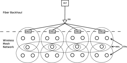
Most previous FiWi access network studies considered a cascaded architecture consisting of a single-stage PON and a multihop WMN, as shown in Fig. 1. Typically, the PON is a conventional IEEE 802.3ah compliant wavelength-broadcasting TDM EPON based on a wavelength splitter/combiner at the remote node (RN), using one time-shared wavelength channel for upstream (ONUs to OLT) transmissions and another time-shared wavelength channel for downstream (OLT to ONUs) transmissions, both operating at a data rate of 1 Gb/s. A subset of ONUs may be located at the premises of residential or business subscribers, whereby each ONU provides fiber-to-the-home/business (FTTH/B) services to a single or multiple attached wired subscribers. Some ONUs have a mesh portal point (MPP) to interface with the WMN. The WMN consists of mesh access points (MAPs) that provide wireless FiWi network access to stations (STAs). Mesh points (MPs) relay the traffic between MPPs and MAPs through wireless transmissions. Most previous FiWi studies assumed a WMN based on IEEE 802.11a/b/g WLAN technologies, offering a maximum raw data rate of 54 Mb/s at the physical layer.
Future FiWi access networks will leverage next-generation PON and WLAN technologies to meet the ever increasing bandwidth requirements. A variety of next-generation PON technologies are currently investigated to enable short-term evolutionary and long-term revolutionary upgrades of coexistent Gigabit-class TDM PONs [44]. Promising solutions for PON evolution toward higher bandwidth per user are () data rate upgrades to 10 Gb/s and higher, and () multi-wavelength channel migration toward wavelength-routing or wavelength-broadcasting WDM PONs with or without cascaded TDM PONs [45, 46]. Similarly, to alleviate the bandwidth bottleneck of the wireless mesh front-end, future FiWi networks are expected to be based on next-generation IEEE 802.11n WLANs, which offer data rates of 100 Mb/s or higher at the MAC service access point, as well as emerging IEEE 802.11ac VHT WLAN technologies that achieve raw data rates up to 6900 Mb/s.
III-A Next-Generation PONs

As shown in Fig. 2, current TDM PONs may evolve into next-generation single- or multi-stage PONs of extended reach by exploiting high-speed TDM and/or multichannel WDM technologies and replacing the splitter/combiner at the RN with a wavelength multiplexer/demultiplexer, giving rise to the following three types of next-generation PONs:
III-A1 High-speed TDM PON
III-A2 Wavelength-broadcasting WDM PON
A wavelength-broadcasting WDM PON has a splitter/combiner at the RN and deploys multiple wavelength channels , as shown in Fig. 2(b). Each of these wavelength channels is broadcast to all connected WDM ONUs and is used for bidirectional transmission. Each WDM ONU selects a wavelength with a tunable bandpass filter (e.g., fiber Bragg grating) and reuses the downstream modulated signal coming from the OLT for upstream data transmission by means of remodulation techniques, e.g., FSK for downstream and OOK for upstream [48].
III-A3 Wavelength-routing multi-stage WDM PON
Fig. 2(c) shows a wavelength-routing WDM PON, where the conventional splitter/combiner at the RN is replaced with a wavelength multiplexer/demultiplexer, e.g., arrayed-waveguide grating (AWG), such that each of the wavelength channels on the common feeder fiber is routed to a different distribution fiber. A given wavelength channel may be dedicated to a single ONU (e.g., business subscriber) or be time shared by multiple ONUs (e.g., residential subscribers). In the latter case, the distribution fibers contain one or more additional stages, whereby each stage consists of a wavelength-broadcasting splitter/combiner and each wavelength channel serves a different sector, see Fig. 2(c). Note that due to the wavelength-routing characteristics of the wavelength multiplexer/demultiplexer, ONUs can be made colorless (i.e., wavelength-independent) by using, for example, low-cost reflective semiconductor optical amplifiers (RSOAs) that are suitable for bidirectional transmission via remodulation [45]. Wavelength-routing multi-stage WDM PONs enable next-generation PONs with an extended optical range of up to 100 km, thus giving rise to long-reach WDM PONs at the expense of additional in-line optical amplifiers. Long-reach WDM PONs promise major cost savings by consolidating optical access and metropolitan area networks [49].
III-B Gigabit-Class WLAN
IEEE 802.11n specifies a number of PHY and MAC enhancements for next-generation WLANs. Applying orthogonal frequency division multiplexing (OFDM) and multiple-input multiple-output (MIMO) antennas in the PHY layer of IEEE 802.11n provides various capabilities, such as antenna diversity (selection) and spatial multiplexing. Using multiple antennas also provides multipath capability and increases both throughput and transmission range. The enhanced PHY layer applies two adaptive coding schemes: space time block coding (STBC) and low density parity check coding (LDPC). IEEE 802.11n WLANs are able to co-exist with IEEE 802.11 legacy WLANs, though in greenfield deployments it is possible to increase the channel bandwidth from 20 MHz to 40 MHz via channel bonding, resulting in significantly increased raw data rates of up to 600 Mb/s at the PHY layer.
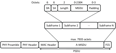
A main MAC enhancement of 802.11n is frame aggregation, which comes in two flavors, as shown in Fig. 3.
Aggregate MAC Service Data Unit (A-MSDU): Multiple MSDUs, each up to 2304 octets long, are joined and encapsulated into a separate subframe, see Fig. 3(a). Specifically, multiple MSDUs are packed into an A-MSDU, which is encapsulated into a PHY service data unit (PSDU). All constituent MSDUs must have the same traffic identifier (TID) value (i.e., same QoS level) and the resultant A-MSDU must not exceed the maximum size of 7935 octets. Each PSDU is prepended with a PHY preamble and PHY header. Although the fragmentation of MSDUs with the same destination address is allowed, A-MSDUs must not be fragmented.
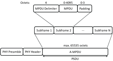
Aggregate MAC Protocol Data Unit (A-MPDU): Multiple MPDUs, each up to 4095 octets long, are joined and inserted in a separate subframe, see Fig. 3(b). Specifically, multiple MPDUs are aggregated into one PSDU of a maximum size 65535 octets. Aggregation of multiple MPDUs with different TID values into one PSDU is allowed by using multi-TID block acknowledgment (MTBA).
Both A-MSDU and A-MPDU require only a single PHY preamble and PHY header. In A-MSDU, the PSDU includes a single MAC header and frame check sequence (FCS), as opposed to A-MPDU where each MPDU contains its own MAC header and FCS. A-MPDU and A-MSDU can be used separately or jointly.
Future Gigabit-class WMNs may be upgraded with emerging IEEE 802.11ac VHT WLAN technologies that exploit further PHY enhancements to achieve raw data rates up to 6900 Mb/s and provide an increased maximum A-MSDU/A-MPDU size of 11406/1048575 octets [50].
IV Network Model
IV-A Network Architecture
We consider a PON consisting of one OLT and attached ONUs. The TDM PON carries one upstream wavelength channel and a separate downstream wavelength channel. We suppose that both the wavelength-broadcasting and the wavelength-routing multi-stage WDM PONs carry bidirectional wavelength channels . In the wavelength-routing multi-stage WDM PON, the ONUs are divided into sectors. We use to index the wavelength channel as well as the corresponding sector. In our model, sector , accommodates ONUs. Specifically, ONUs with indices between and belong to sector , i.e., form the set of nodes
| (1) |
Thus, sector comprises ONUs , sector comprises ONUs , and so on, while we assign the index to the OLT. The one-way propagation delay between OLT and ONUs of sector is (in seconds) and the data rate of the associated wavelength channel is denoted by (in bit/s). Hence, each sector of the wavelength-routing multi-stage WDM PON is allowed to operate at a different data rate serving a subset of ONUs located at a different distance from the OLT (e.g., business vs. residential service areas). For ease of exposition, we assume that in the wavelength-broadcasting TDM and WDM PONs all wavelength channels operate at the same data rate (in bit/s) and that all ONUs have the one-way propagation delay (in seconds) from the OLT.
All or a subset of the ONUs are equipped with an MPP to interface with the WMN. The WMN is composed of different zones , whereby each zone operates on a distinct frequency such that the frequencies of neighboring zones do not overlap. Frequencies may be spatially reused in nonadjacent zones. A subset of MPs are assumed to be equipped with multiple radios to enable them to send and receive data in more than one zone and thereby serve as relay nodes between adjacent zones. We denote each radio operating in a given relay MP in a given zone by a unique . The remaining MPs as well as all MPPs, MAPs, and STAs are assumed to have only a single radio operating on the frequency of their corresponding zone. All wireless nodes are assumed to be stationary; incorporating mobility is left for future research. Adopting the notation proposed in [51], we let denote the set of multi-radio relay MPs and denote the set of single-radio MPs, MPPs, MAPs, and STAs in zone . Note that set is empty if there are only single-radio MPs in zone . Note that due to this set definition each multi-radio MP is designated by multiple ; one and corresponding set for each zone in which it can send and receive. The WMN operates at a data rate (in bit/s).
In the WMN, we assume that the bit error rate (BER) of the wireless channel is . On the contrary, the BER of the PON is assumed to be negligible and is therefore set to zero. However, individual fiber links may fail due to fiber cuts and become unavailable for routing traffic across the PON, as described next in more detail. Throughout, we neglect nodal processing delays.
IV-B Traffic Model and Routing
We denote for the set of FiWi network nodes that act as traffic sources and destinations. Specifically, we consider to contain the OLT, the ONUs (whereby a given ONU models the set of end users with wired access to the ONU), and a given number of STAs. In our model, MPPs, MPs, and MAPs forward in-transit traffic, without generating their own traffic. Hence, the number of traffic sources/destinations is given by . Furthermore, we define the traffic matrix , where represents the number of frames per second that are generated at FiWi network node and destined to FiWi network node (note that for ). We allow for any arbitrary distribution of the frame length (in bit) and denote and for the mean and variance of the length of a frame, respectively. The traffic generation is assumed to be ergodic and stationary.
Our capacity and delay analysis flexibly accommodates any routing algorithm. For each pair of FiWi network source node and destination node , a particular considered routing algorithm results in a specific traffic rate (in frames/s) sent in the fiber domain and traffic rate sent in the wireless domain. A conventional ONU without an additional MPP cannot send in the wireless domain, i.e., , and sends its entire generated traffic to the OLT, i.e., . On the other hand, an ONU equipped with an MPP can send in the wireless domain, i.e., . Note that we allow for multipath routing in both the fiber and wireless domains, whereby traffic coming from or going to the OLT may be sent across a single or multiple ONUs and their collocated MPPs. We consider throughout first-come-first-served service in each network node.
V Fiber Backhaul Network
V-A Capacity Analysis
For the wavelength-routing multi-stage WDM PON, we define the normalized downstream traffic rate (intensity) in sector , as
| (2) |
where the first term represents the traffic generated by the OLT for sector and the second term accounts for the traffic from all ONUs sent to sector via the OLT. We define the upstream traffic rate (in frames/s) of ONU as
| (3) |
where the first term denotes traffic destined to the OLT and the second term represents the traffic sent to other ONUs via the OLT. The normalized upstream traffic rate (intensity) of sector is
| (4) |
For stability, the normalized downstream and upstream traffic rates have to satisfy
| (5) |
in each sector , of the wavelength-routing multi-stage WDM PON.
In the wavelength-broadcasting TDM PON () and WDM PON (), we define the upstream traffic intensity and downstream traffic intensity as:
| (6) |
| (7) |
The TDM and WDM PONs are stable if and . The delay analysis of Section V-B applies only for a stable network, which can be ensured through admission control techniques.
V-B Delay Analysis
In the wavelength-routing multi-stage WDM PON, the OLT sends a downstream frame to an ONU in sector by transmitting the frame on wavelength , which is received by all ONUs in the sector. We model all downstream transmissions in sector to emanate from a single queue. For Poisson frame traffic, the downstream queueing delay is thus modeled by an M/G/1 queue characterized by the Pollaczek-Khintchine formula [52]
| (8) |
giving the total downstream frame delay
| (9) |
Weighing the downstream delays in the sectors by the relative downstream traffic intensities in the sectors, gives the average downstream delay of the wavelength-routing multi-stage WDM PON
| (10) |
For the upstream delay, we model each wavelength channel , as a single upstream wavelength channel of a conventional EPON. Accordingly, from Eq. (39) in [53], we obtain for the mean upstream delay of sector
| (11) |
and the average upstream delay of the wavelength-routing multi-stage WDM PON equals
| (12) |
To improve the accuracy of our delay analysis, we take into account that traffic coming from an ONU in sector and destined to ONU in sector is queued at the intermediate OLT before being sent downstream to ONU , i.e., the OLT acts like an insertion buffer between ONUs and . Consequently, to compensate for the queueing delay at the OLT we apply the method proposed in [54] by subtracting the correction term
| (13) |
whereby for the setting that for all channels
| (14) |
denotes the rate of upstream traffic in sector destined for sector , from the above calculated mean downstream delay. Thus, for sector , the corrected mean downstream delay is given by
| (15) |
By replacing with in Eq. (10) we obtain a more accurate calculation of the average downstream delay for the wavelength-routing multi-stage WDM PON, as examined in Section VIII.
Next, we evaluate the average downstream and upstream delays for the wavelength-broadcasting TDM PON () and WDM PON (). With the aforementioned correction term the average downstream and upstream delays are given by
| (16) |
and
| (17) |
respectively, whereby
| (18) |
VI Wireless Front-End Network
So far, we have analyzed only the optical fiber backhaul of the FiWi network. Next, we focus on the wireless front-end. In the following, we derive multiple relations between known parameter values and unknown variables. Afterwards, we outline how to obtain the unknowns numerically. More specifically, in Sections VI-A–VI-D we build on and adapt existing models of distributed coordination [25, 26, 51] and frame aggregation [27] in WLANs to formulate the basic frame aggregate transmission and collision probabilities as well as time slot duration in the distributed access system. We note that these existing models have primarily focused on accurately representing the collision probabilities and system throughput; we found that directly adapting these existing models gives delay characterizations that are reasonably accurate only for specific scenarios, such as single-hop networking, but are very coarse for multi-hop networking. In Sections VI-E–VI-G we develop a general multihop delay model that is simple, yet accurate by considering the complete service time of a frame aggregate in the wireless front-end network carrying traffic streams from and to both wireless and optical network nodes.
VI-A Frame Traffic Modeling
As defined in Section IV-A, we denote the radio operating in a given STA or ONU equipped with an MPP by a unique . Moreover, we denote each radio operating in a given relay MP in a unique zone by a unique . For ease of exposition, we refer to “radio ” henceforth as “node .”
Similar to [51], we model time as being slotted and denote for the mean duration of a time slot at node . The mean time slot duration corresponds to the average time period required for a successful frame transmission, a collided frame transmission, or an idle waiting slot at node and is evaluated in Section VI-D. We let denote the probability that there is a frame waiting for transmission at node in a time slot.
For an STA or ONU with collocated MPP we denote for the traffic load that emanates from node , i.e.,
| (19) |
For a relay MP we obtain for a given wireless mesh routing algorithm the frame arrival rate for each of the MP’s radios associated with a different zone :
| (20) |
whereby and denote any pair of STA or ONU with collocated MPP that send traffic on a path via relay MP , as computed by the given routing algorithm for the wireless mesh front-end of the FiWi network.
For exponentially distributed inter-frame arrival times with mean (which occur for a Poisson process with rate ), is related to the offered frame load at node during mean time slot duration via
| (21) |
VI-B Frame Aggregate Error Probability
In this section, we first characterize the sizes of the frame aggregates and then the frame aggregate error probability. For a prescribed distribution of the size (in bit) of a single frame, e.g., the typical trimodal IP packet size distribution, the distribution of the size (in bit) of a transmitted A-MSDU or A-MPDU can be obtained as the convolution of with itself, i.e.,
| (22) |
The number of required convolutions equals the number of frames carried in the aggregate, which in turn depends on the minimum frame size, including the MAC-layer overhead of the corresponding frame aggregation scheme, and the maximum size of an A-MSDU/A-MPDU (see Fig. 3). From the distribution we obtain the average frame aggregate sizes and . Correspondingly, we divide the traffic rate (in frames/s) by the average number of frames in an aggregate to obtain the traffic rate in frame aggregates per second.
Moreover, as ground work for Section VI-D we obtain the average size of the longest A-MSDU, , and longest A-MPDU, , involved in a collision with the simplifying assumption of neglecting the collision probability of more than two packets [25] as
| (23) |
The probability of an erroneously transmitted frame aggregate, referred to henceforth as “transmission error”, can be evaluated in terms of bit error probability and size of a transmitted A-MSDU (with distribution ) with [55, Eqn. (16)]; for A-MPDU, can be evaluated in terms of and the sizes of the aggregated frames with [55, Eqn. (18)]. In particular,
| (24) |
where is the size of a transmitted A-MSDU (with distribution ), index runs from one to the total number of aggregated frames, and is the size of the th frame in a transmitted A-MPDU.
VI-C Probabilities for Frame Aggregate Collision and Successful Frame Aggregate Transmission
Following [51], we note that the transmission of any transmitting node in zone cannot collide if none of the other nodes transmits, i.e., we obtain the collision probability as
| (25) |
where denotes the transmission probability of WMN node . Note that if the considered node is a relay MP, Eq. (25) holds for each associated zone (and corresponding radio ). We define the probability of either a collision or transmission error , in brief collision/transmission error probability, as
| (26) |
The transmission probability for any node can be evaluated as a function of the frame waiting probability , the frame collision/transmission error probability , the minimum contention window , and the maximum backoff stage by [51, Eqn. (1)], as explained in [26]. In particular,
| (27) |
with
| (28) | |||||
where is node ’s minimum contention window, is the node’s maximum window size, and is the maximum backoff stage.
The probability that there is at least one transmission taking place in zone in a given time slot is given by
| (29) |
A successful frame aggregate transmission occurs if exactly one node transmits (and all other nodes are silent), given that there is a transmission, i.e.,
| (30) |
VI-D Duration of Single Frame Aggregate Transmission
We denote for the duration of an empty time slot without any data transmission on the wireless channel in zone , which occurs with probability . With probability there is a transmission in a given time slot in zone , which is successful with probability and unsuccessful (resulting in a collision) with the complementary probability .
We denote for the mean duration of a successful frame aggregate transmission and is the mean duration of a frame aggregate transmission with collision in zone . Note that and depend on the frame aggregation technique (A-MSDU or A-MPDU) and on the access mechanism (basic access denoted by or RTS/CTS denoted by ). For the basic access mechanism, we define , where denotes the propagation delay and the WMN data rate. For the RTS/CTS access mechanism, we define . (Note that in IEEE 802.11n the parameters ACK, RTS, and CTS as well as the PHY/MAC Header and FCS below are given in bits, while the other parameters are given in seconds.) Then, for a successful frame aggregate transmission we have:
| (31) |
Moreover, with , for a collided frame aggregate transmission we have:
| (32) |
as well as for both A-MSDU and A-MPDU,
| (33) |
Thus, we obtain the expected time slot duration at node in zone of our network model (corresponding to [25, Eq. (13)]) as
| (34) |
Equations (21), (26), [51, Eqn. (1)], and (34) can be solved numerically for the unknown variables , , , and for each given set of values for the known network model parameters. We use the obtained numerical solutions to evaluate the mean delay at node as analyzed in the following Sections VI-E and VI-F.
VI-E Service Time for Frame Aggregate
We proceed to evaluate the expected service (transmission) time for a frame aggregate, which may require several transmission attempts, at a given node . With the basic access mechanism, the transmission of the frame aggregate occurs without a collision () or transmission error with probability (26), requiring one . With probability , the frame aggregate suffers , collisions or transmission errors, requiring backoff procedures and re-transmissions. Thus, the expected service time for basic access is
| (35) |
For the RTS/CTS access mechanism, collisions can occur only for the RTS or CTS frames (which are short and have negligible probability of transmission errors), whereas transmission errors may occur for the frame aggregates. Collisions require only retransmissions of the RTS frame, whereas transmission errors require retransmissions of the entire frame aggregate. More specifically, only one frame transmission () is required if no transmission error occurs; this event has probability . This transmission without transmission error may involve , collisions of the RTS/CTS frames. On the other hand, two frame transmissions () are required if there is once a transmission error; this event has probability . This scenario requires twice an RTS/CTS reservation, which each time may experience collisions, as well as two full frame transmission delays . Generally, , frame transmissions are required if times there is a frame transmission error. Each of the frame transmission attempts requires an RTS/CTS reservation and a full frame transmission delay . In summary, we evaluate the mean service delay for a frame aggregate with RTS/CTS access as
| (36) | |||||
VI-F Delay at WMN Node
We first evaluate the overall service time from the time instant when a frame aggregate arrives at the head of the queue at node to the completion of its successful transmission. Subsequently, with characterizing the overall service time at node , we evaluate the queueing delay .
The overall service time is given by the service time required for transmitting a frame aggregate and the sensing delay required for the reception of frame aggregates by node from other nodes, i.e.,
| (37) |
As a first step towards modeling the sensing delay at a node , we consider the service times at nodes and scale these service times linearly with the corresponding traffic intensities to obtain the sensing delay component
| (38) |
As a second modeling step, we consider the service times plus sensing delay components scaled by the respective traffic intensities to obtain the sensing delay
| (39) |
employed in the evaluation of the overall service delay (37).
We approximate the queue at node by an M/M/1 queue with mean arrival rate and mean service time . This queue is stable if
| (40) |
The total delay (for queueing plus service) at node is then given by
| (41) |
If node is an ONU with a collocated MPP the accuracy of the queueing delay calculation is improved by subtracting a correction term:
| (42) |
for the wavelength-broadcasting TDM PON and WDM PON, or
| (43) |
for the wavelength-routing multi-stage WDM PON, whose sector accommodates the ONU with collocated MPP. Note that or accounts for the traffic of all pairs of source node and destination node traversing ONU from the fiber backhaul towards the wireless front-end network.
VI-G Delay on WMN Path
In order to obtain the delay in the wireless front-end of our FiWi network, we have to average the sums of the nodal delays of all possible paths for all pairs of source node and destination node :
| (44) |
with the queueing delay correction terms
| (45) |
whereby is the traffic intensity at node due to traffic flowing from source node to destination node .
VII FiWi Network Stability and Delay
The entire FiWi access network is stable if and only if all of its optical and wireless subnetworks are stable. If the optical backhaul consists of a wavelength-routing multi-stage WDM PON the stability conditions in Eq. (5) must be satisfied. In the case of the wavelength-broadcasting TDM and WDM PON, the optical backhaul is stable if both and defined in Eqs. (6) and (7), respectively, are smaller than one. The wireless mesh front-end is stable if the stability condition in Eq. (40) is satisfied for each WMN node.
We obtain the mean end-to-end delay of the entire bimodal FiWi access network as
| (46) |
VIII Numerical and Simulation Results
We set the parameters of the FiWi mesh front-end to the default values for next-generation WLANs [56], see Table I. We consider a distance of 1 km between any pair of adjacent WMN nodes (which is well within the maximum distance of presently available outdoor wireless access points), translating into a propagation delay of s.
| Parameter | Value |
|---|---|
| Min. contention window | 16 |
| Max. backoff state | 6 |
| Empty slot duration | 9 s |
| SIFS | 16 s |
| DIFS | 34 s |
| PHY Header | 20 s |
| MAC Header | 36 bytes |
| RTS | 20 bytes |
| CTS | 14 bytes |
| ACK | 14 bytes |
| FCS | 4 bytes |
VIII-A Model Verification
We first verify the accuracy of our probabilistic analysis by means of simulations.
VIII-A1 Configuration
In our initial verifying simulations, we consider the FiWi network configuration of Fig. 4. The fiber backhaul is a TDM PON, or a wavelength-broadcasting/routing WDM PON with bidirectional wavelength channels (, ), each operating at Gb/s (compliant with IEEE 802.3ah). In the case of the wavelength-routing (WR) WDM PON, the two sectors are defined as: : and : . All four ONUs are located 20 km from the OLT (translating into a one-way propagation delay ms) and are equipped with an MPP. The WMN is composed of the aforementioned 4 MPPs plus 16 STAs and 4 MPs, which are distributed over 11 wireless zones, as shown in Fig. 4. For instance, the WMN zone containing comprises 1 MPP, 2 STAs, and 1 MP. MPPs and STAs use a single radio, whereas MPs use 3, 4, 4, 3 radios from left to right in Fig. 4. All WMN nodes apply the RTS/CTS access mechanism. The WMN operates at Mb/s (compliant with IEEE 802.11n) with a bit error rate of .
VIII-A2 Traffic and Routing Assumptions
We consider Poisson traffic with fixed-size frames of 1500 bytes (octets). We use A-MSDU for frame aggregation, whereby each A-MSDU carries the maximum permissible payload of 5 frames, see Fig. 3(a). Similar to [5], we consider two operation modes: () WMN-only mode which has no fiber backhaul in place; and WMN nodes apply minimum wireless hop routing () wireless-optical-wireless mode which deploys the FiWi network configuration of Fig. 4. For both modes, we consider the minimum interference routing algorithm [6], which selects the path with the minimum number of wireless hops. We compare different routing algorithms in Section VIII-B.
VIII-A3 Verifying Simulations
The simulation results presented in [5] indicate that the throughput performance of WMNs deteriorates much faster for increasing peer-to-peer traffic among STAs than that of FiWi networks, while WMN and FiWi networks achieve the same throughput when all traffic is destined to the Internet. For comparison with [5], we consider peer-to-peer (P2P) traffic, where each frame generated by a given STA is destined to any other of the remaining 15 STAs with equal probability 1/15, and upstream traffic, where all frames generated by the STAs are destined to the OLT. Fig. 5 depicts the results of our probabilistic analysis for the mean delay as a function of the mean aggregate throughput of a stand-alone WMN network and a TDM PON based FiWi network for P2P and upstream traffic. The figure also shows verifying simulation results and their 95% confidence intervals, whereby simulations were run 100 times for each considered traffic load111Our simulator is based on OMNeT++ and uses the communication networks package inetmanet with extensions for frame aggregation, wireless multihop routing, TDM/WDM PONs, and integrated WMN/PON routing..
We observe from Fig. 5 that the mean delay of the WMN increases sharply as the mean aggregate throughput asymptotically approaches its maximum data rate of 300 Mb/s. We also confirm the findings of [5] that under P2P traffic the mean aggregate throughput can be increased by using a TDM PON as fiber backhaul to offload the wireless mesh front-end at the expense of a slightly increased mean delay due to the introduced upstream and downstream PON delay to and from the OLT. As opposed to [5], however, Fig. 5 shows that the throughput-delay performance of the considered FiWi network is further improved significantly under upstream traffic. These different observations are due to the fact that in [5] the single-radio single-channel WMN based on legacy IEEE 802.11a WLAN with a limited data rate of 54 Mb/s suffered from severe channel congestion close to the MPPs, which is alleviated in the multi-radio multi-channel WMN based on next-generation high-throughput WLAN technologies.


Next, we verify different FiWi network architectures and their constituent subnetworks for uniform and nonuniform traffic for minimum (wireless or optical) hop routing [5]. Fig. 6 depicts the throughput-delay performance of a stand-alone WMN front-end, stand-alone TDM PON, and a variety of integrated FiWi network architectures using different fiber backhaul solutions, including conventional TDM PON, wavelength-broadcasting WDM PON (WDM PON), and wavelength-routing WDM PON (WR PON). In the TDM PON only (WMN only) scenario under uniform traffic, each ONU (STA) generates the same amount of traffic and each generated frame is destined to any of the remaining ONUs (STAs) with equal probability. As expected, the WMN and TDM PON saturate at roughly 300 Mb/s and 1 Gb/s, respectively, and the TDM PON is able to support much higher data rates per source node (ONU) at lower delays than the WMN. Furthermore, we observe from Fig. 6 that under uniform traffic conditions, where STAs and ONUs send unicast traffic randomly uniformly distributed among themselves, FiWi networks based on a wavelength-broadcasting WDM PON or a WR PON give the same throughput-delay performance, clearly outperforming their single-channel TDM PON based counterpart. However, there is a clear difference between WDM PON and WR PON fiber backhauls when traffic becomes unbalanced. To see this, let us consider a nonuniform traffic scenario, where and and their 4 associated STAs (see Fig. 4) generate 30% more traffic than the remaining ONUs and STAs. Under such a nonuniform traffic scenario, a FiWi network based on a wavelength-broadcasting WDM PON performs better, as shown in Fig. 6. This is due to the fact that the WDM PON provides the two heavily loaded and with access to both wavelength channels, as opposed to the WR PON, thus resulting in an improved throughput-delay performance.
VIII-B FiWi Routing Algorithms
Recall from Section IV-B that our capacity and delay analysis flexibly accommodates any routing algorithm and allows for multipath routing in both the fiber and wireless domains. In this section, we study the impact of different routing algorithms on the throughput-delay performance of next-generation FiWi access networks in greater detail, including their sensitivity to key network parameters. Specifically, we examine the following single-path routing algorithms:
Minimum hop routing: Conventional shortest path routing selects for each source-destination node pair the path minimizing the required number of wireless and/or optical hops.
Minimum interference routing [6]: The path with the minimum wireless hop count is selected. The rationale behind this algorithm is that the maximum throughput of wireless networks is typically much lower compared to the throughput in optical networks. Thus, minimizing the wireless hop count tends to increase the maximum FiWi network throughput.
Minimum delay routing: Similar to the previously proposed WMN routing algorithms DARA [7], CaDAR [9], and RADAR [10], we apply a slightly extended minimum delay routing algorithm, which aims at selecting the path that minimizes the end-to-end delay of Eq. (46) across the entire bimodal FiWi access network. The applied minimum delay routing algorithm is a greedy algorithm and proceeds in two steps. In the initialization step, paths are set to the minimum hop routes. The second step computes for each source-destination node pair the path with the minimum end-to-end delay under given traffic demands.
Optimized FiWi routing algorithm (OFRA): We propose the optimized FiWi routing algorithm (OFRA), which proceeds in two steps similar to minimum delay routing. After the initialization step to minimum hop routes, the second step of OFRA computes for each source-destination node pair the path with the minimization objective
| (47) |
where represents the long-run traffic intensity at a generic FiWi network node , which may be either an optical node belonging to the fiber backhaul or a wireless node belonging to the wireless mesh front-end. Based on a combination of historic traffic patterns as well as traffic measurements and estimations similar to [57, 58, 59], the traffic intensities used in OFRA can be periodically updated with strategies similar to [9, 60]. These long-run traffic intensities vary typically slowly, e.g., with a diurnal pattern, allowing essentially offline computation of the OFRA paths. More precisely, for the WR PON we have (see Eq. (2)) if node is the OLT and (see Eq. (4)) if node is an ONU. For the wavelength-broadcasting TDM and WDM PON, we have (Eq. (7)) and (Eq. (6)) if node is the OLT or an ONU, respectively. For a wireless node , is given by the left-hand side of (40).
OFRA’s path length measure includes the maximum traffic intensity along a path in order to penalize paths with a high traffic intensity at one or more FiWi network nodes. For a given set of traffic flows, OFRA minimizes the traffic intensities, particularly the high ones, at the FiWi network nodes. Decreasing the traffic intensities tends to allow for a higher number of supported traffic flows and thus higher throughput.
To allow for a larger number of possible paths for the following
numerical investigations of the different considered routing algorithms,
we double the FiWi network configuration of Fig. 4.
We consider a wavelength-routing (WR) WDM PON with
a total of 8 ONU/MPPs, 8 MPs, and 32 STAs in 22 wireless zones, whereby
ONU/MPPs 1-4 and ONU/MPPs 5-8 are served on wavelength channel
and , respectively. Furthermore, to evaluate
different traffic loads in the optical and wireless domains, we consider
the following traffic matrix for the OLT, ONUs, and
STAs:
0 1 …O O+1 …O + N
0 ( 0 BαBαBαααα) 1 Bα0 BαBαααα⋮BαBα0 BααααO BαBαBα0 αααO+1 αααα0 αα⋮ααααα0 αO+N αααααα0 ,
where denotes the mean traffic rate (in frames/second).
The parameter can be used to test different traffic
intensities in the PON, since
the ONUs could be underutilized compared to the WMN in the
considered topology.
Recall from Fig. 1 that ONUs may
serve multiple subscribers with wired ONU access,
whose aggregate traffic leads to an increased load at ONUs.

For a conventional WR WDM PON with a typical optical fiber range of 20 km, Fig. 7 illustrates that OFRA yields the best throughput-delay performance for , i.e., every optical and wireless FiWi node generates the same amount of traffic. Minimum interference routing tends to overload the wireless MPP interfaces as it does not count the fiber backhaul as a hop, resulting in high delays.
The throughput-delay performance of the four considered FiWi routing algorithms largely depends on the given traffic loads and length of the fiber backhaul. Fig. 8 depicts their throughput-delay performance for () a conventional 20 km range and () a 100 km long-reach WR WDM PON, whereby in both configurations we set , i.e., the amount of generated traffic among optical nodes (OLT and ONUs) is 100 times higher than that between node pairs involving at least one wireless node (STA). More precisely, all the (increased) inter-ONU/OLT traffic is sent across the WDM PON only, thus creating a higher loaded fiber backhaul. We observe from Fig. 8 that in general all four routing algorithms achieve a higher maximum aggregate throughput due to the increased traffic load carried on the fiber backhaul.
We observe that for a conventional 20 km range WR WDM PON with small to medium traffic loads, OFRA gives slightly higher delays than the other considered routing algorithms. This observation is in contrast to Fig. 7, though in both figures OFRA yields the highest maximum aggregate throughput. We have measured the traffic on the optical and wireless network interfaces of each ONU/MPP. Our measurements show that at low to medium traffic loads with , OFRA routes significantly less traffic across the WDM PON than the other routing algorithms, but instead uses the less loaded wireless mesh front-end. This is due to the objective of OFRA to give preference to links with lower traffic intensities. As a consequence, for , OFRA routes relatively more traffic over lightly loaded wireless links, even though this implies more wireless hops, resulting in a slightly increased mean delay compared to the other routing algorithms at low to medium loads.

Fig. 8 also shows the impact of the increased propagation delay in a long-reach WDM PON with a fiber range of 100 km between OLT and ONUs. Aside from a generally increased mean delay, we observe that minimum hop and minimum interference routing as well as OFRA provide comparable delays at low to medium traffic loads, while the maximum achievable throughput differences at high traffic loads are more pronounced than for the 20 km range. The favorable performance of OFRA at high traffic loads is potentially of high practical relevance since access networks are the bottlenecks in many networking scenarios and thus experience relatively high loads while core networks operate at low to medium loads.
Fig. 8 illustrates that minimum delay routing performs poorly in long-reach WDM PON based FiWi access networks. Our measurements indicate that minimum delay routing utilizes the huge bandwidth of the long-reach WDM PON much less than the other routing algorithms in order to avoid the increased propagation delay. As a consequence, with minimum delay routing most traffic is sent across the WMN, which offers significantly lower data rates than the fiber backhaul, resulting in a congested wireless front-end and thereby an inferior throughput-delay performance.
VIII-C Fiber Failures
To highlight the flexibility of our analysis, we note that it accommodates any type and number of fiber failures. Fiber failures represent one of the major differences between optical (wired) fiber and wireless networks and affect the availability of bimodal FiWi networks. In the event of one or more distribution fiber cuts, the corresponding disconnected ONU/MPP(s) turn(s) into a conventional wireless MP without offering gateway functions to the fiber backhaul any longer. FiWi access network survivability for arbitrary fiber failure probabilities has been analyzed in [40].
Fig. 9 illustrates the detrimental impact of distribution fiber failures on the throughput-delay performance of a 20 km range wavelength-routing WDM PON, which is typically left unprotected due to the small number of cost-sharing subscribers and cost-sensitivity of access networks.

We also note that the analytical framework is able to account for other types of network failure, e.g., ONU/MPP failures. In this case, malfunctioning ONU/MPPs become unavailable for both optical and wireless routing.
In principle, FiWi access networks can be made more robust against fiber failures through various optical redundancy strategies, such as ONU dual homing, point-to-point interconnection fibers between pairs of ONUs, fiber protection rings to interconnect a group of closely located ONUs by a short-distance fiber ring, or meshed PON topologies [35]. These redundancy strategies in general imply major architectural and ONU modifications of the FiWi access network of Fig. 1 under consideration. To incorporate such topological PON modifications, the fiber part of the capacity and delay analysis would need to be modified accordingly.
VIII-D Very High Throughput WLAN
Our analysis is also applicable to the emerging IEEE standard 802.11ac for future VHT WLANs with raw data rates up to 6900 Mb/s. In addition to a number of PHY layer enhancements, IEEE 802.11ac will increase the maximum A-MSDU size from 7935 to 11406 octets and the maximum A-MPDU size from 65535 octets to 1048575 octets. Both enhancements can be readily accommodated in our analysis by setting the parameters and accordingly.

Fig. 10 illustrates the FiWi network performance gain achieved with a wireless front-end based on VHT WLAN instead of IEEE 802.11n WLAN with maximum data rate of 600 Mb/s, for minimum hop routing, an optical range of 20 km, and . For a wavelength-routing WDM PON operating at a wavelength channel data rate of 1 Gb/s, we observe from Fig. 10 that VHT WLAN roughly triples the maximum mean aggregate throughput and clearly outperforms 600 Mb/s 802.11n WLAN in terms of both throughput and delay. Furthermore, the figure shows that replacing the 1 Gb/s wavelength-routing WDM PON with its high-speed 10 Gb/s counterpart (compliant with the IEEE 802.3av 10G-EPON standard) does not yield a higher maximum aggregate throughput, but it does lower the mean delay especially at medium traffic loads before wireless links at the optical-wireless interfaces get increasingly congested at higher traffic loads.
IX Conclusions
A variety of routing algorithms have recently been proposed for integrated FiWi access networks based on complementary EPON and WLAN-mesh networks. In this article, we presented the first analytical framework to quantify the performance of FiWi network routing algorithms, validate previous simulation studies, and provide insightful guidelines for the design of novel integrated optical-wireless routing algorithms for future FiWi access networks leveraging next-generation PONs, notably long-reach 10+ Gb/s TDM/WDM PONs, and emerging Gigabit-class WLAN technologies. Our analytical framework is very flexible and can be applied to any existing or new optical-wireless routing algorithm. Furthermore, it takes the different characteristics of disparate optical and wireless networking technologies into account. Beside their capacity mismatch and bit error rate differences, the framework also incorporates arbitrary frame size distributions, traffic matrices, optical/wireless propagation delays, data rates, and fiber cuts. We investigated the performance of minimum hop, minimum interference (wireless hop), minimum delay, and our proposed OFRA routing algorithms. The obtained results showed that OFRA yields the highest maximum aggregate throughput for both conventional and long-reach wavelength-routing WDM PONs under balanced and unbalanced traffic loads. For a higher loaded fiber backhaul, however, OFRA gives priority to lightly loaded wireless links, leading to an increased mean delay at small to medium wireless traffic loads. We also observed that using VHT WLAN helps increase the maximum mean aggregate throughput significantly, while high-speed 10 Gb/s WDM PON helps lower the mean delay especially at medium traffic loads.
There are several important directions for future research. One direction is to examine mechanisms for providing qulity of service or supporting specific traffic types, see e.g., [61, 62]. Further detailed study of the impact of different dynamic bandwidth allocation approaches for long-reach PONs, e.g., [63, 64, 65, 66, 67, 68], and their effectiveness in integrated FiWi networks is of interest. Yet another direction is the examine the internetworking of FiWi networks with metropolitan area networks [69, 70, 71, 72, 73, 74].
References
- [1] S. Sarkar, H.-H. Yen, S. Dixit, and B. Mukherjee, “Hybrid Wireless-Optical Broadband Access Network (WOBAN): Network Planning Using Lagrangean Relaxation,” IEEE/ACM Transactions on Networking, vol. 17, no. 4, pp. 1094–1105, Aug. 2009.
- [2] M. A. Ali, G. Ellinas, H. Erkan, A. Hadjiantonis, and R. Dorsinville, “On the Vision of Complete Fixed-Mobile Convergence,” IEEE/OSA J. Lightwave Technol., vol. 28, no. 16, pp. 2343–2357, Aug. 2010.
- [3] N. Ghazisaidi and M. Maier, “Fiber-Wireless (FiWi) Networks: Challenges and Opportunities,” IEEE Network, vol. 25, no. 1, pp. 36–42, Jan./Feb. 2011.
- [4] ——, “Hierarchical Frame Aggregation Techniques for Hybrid Fiber-Wireless Access Networks,” IEEE Communications Magazine, vol. 49, no. 9, pp. 64–73, Sep. 2011.
- [5] Z. Zheng, J. Wang, and J. Wang, “A Study of Network Throughput Gain in Optical-Wireless (FiWi) Networks Subject to Peer-to-Peer Communications,” in Proc., IEEE ICC, Jun. 2009, pp. 1–6.
- [6] Z. Zheng, J. Wang, and X. Wang, “ONU Placement in Fiber-Wireless (FiWi) Networks Considering Peer-to-Peer Communications,” in Proc., IEEE GLOBECOM, Nov./Dec. 2009, pp. 1–7.
- [7] S. Sarkar and et al., “A Novel Delay-Aware Routing Algorithm (DARA) for a Hybrid Wireless-Optical Broadband Access Network (WOBAN),” IEEE Network, vol. 22, no. 3, pp. 20–28, Jan./Feb. 2008.
- [8] X. Chen and et al., “Delay-Differentiated Routing Algorithm to Enhance Delay Performance of WOBAN,” in Proc., International Conference on Optical Internet (COIN), Jul. 2010, pp. 1–4.
- [9] A. Reaz, V. Ramamurthi, S. Sarkar, D. Ghosal, S. Dixit, and B. Mukherjee, “CaDAR: An Efficient Routing Algorithm for a Wireless-Optical Broadband Access Network (WOBAN),” IEEE/OSA Journal of Optical Communications and Networking, vol. 1, no. 5, pp. 392–403, Oct. 2009.
- [10] S. Sarkar and et al., “RADAR: Risk-and-Delay Aware Routing Algorithm in a Hybrid Wireless-Optical Broadband Access Network (WOBAN),” in Proc., OFC/NFOEC, Mar. 2007, pp. 1–3.
- [11] X. Shao, Y. K. Yeo, L. H. Ngoh, X. Cheng, W. Rong, and L. Zhou, “Availability-Aware Routing for Large-Scale Hybrid Wireless-Optical Broadband Access Network,” in Proc., OFC, Mar. 2010, pp. 1–3.
- [12] J. Wang, K. Wu, S. Li, and C. Qiao, “Performance Modeling and Analysis of Multi-Path Routing in Integrated Fiber-Wireless Networks,” in Proc., Mini-Conference at IEEE INFOCOM, Mar. 2010, pp. 1–5.
- [13] P. Chowdhury, M. Tornatore, S. Sarkar, and B. Mukherjee, “Building a Green Wireless-Optical Broadband Access Network (WOBAN),” IEEE J. Lightw. Techn., vol. 28, no. 16, pp. 2219–2229, Aug. 2010.
- [14] G. Shen, R. S. Tucker, and C.-J. Chae, “Fixed Mobile Convergence Architectures for Broadband Access: Integration of EPON and WiMAX,” IEEE Communications Magazine, vol. 45, no. 8, pp. 44–50, Aug. 2007.
- [15] M. Maier and N. Ghazisaidi, FiWi Access Networks. Cambridge University Press, 2012.
- [16] N. Antunes, C. Fricker, P. Roberts, and J. Roberts, “Traffic capacity of large WDM passive optical networks,” in Proc., Int. Teletraffic Congress, Sep. 2010.
- [17] F. Aurzada, M. Scheutzow, M. Reisslein, and M. Maier, “Towards a fundamental understanding of the stability and delay of offline WDM EPONs,” IEEE/OSA J. Optical Communications and Networking, vol. 2, no. 1, pp. 51–66, Jan. 2010.
- [18] F. Aurzada, M. Scheutzow, M. Reisslein, N. Ghazisaidi, and M. Maier, “Capacity and delay analysis of next-generation passive optical networks (NG-PONs),” IEEE Transactions on Communications, vol. 59, no. 5, pp. 1378–1388, May 2011.
- [19] S. Bharati and P. Saengudomlert, “Analysis of mean packet delay for dynamic bandwidth allocation algorithms in EPONs,” IEEE/OSA Journal of Lightwave Technology, vol. 28, no. 23, pp. 3454–3462, 2010.
- [20] B. Lannoo, L. Verslegers, D. Colle, M. Pickavet, M. Gagnaire, and P. Demeester, “Analytical model for the IPACT dynamic bandwidth allocation algorithm in EPONs,” OSA Journal of Optical Networking, vol. 6, no. 6, pp. 677–688, Jun. 2007.
- [21] M. McGarry, M. Reisslein, F. Aurzada, and M. Scheutzow, “Shortest propagation delay (SPD) first scheduling for EPONs with heterogeneous propagation delays,” IEEE Journal on Selected Areas in Communications, vol. 28, no. 6, pp. 849–862, Aug. 2010.
- [22] M. T. Ngo, A. Gravey, and D. Bhadauria, “A mean value analysis approach for evaluating the performance of EPON with Gated IPACT,” in Proc. of Int. Conference on Optical Network Design and Modeling (ONDM), Mar. 2008, pp. 1–6.
- [23] J. Zhang and N. Ansari, “Scheduling Hybrid WDM/TDM Passive Optical Networks With Nonzero Laser Tuning Time,” IEEE/ACM Transactions on Networking, vol. 19, no. 4, pp. 1014–1027, Aug. 2011.
- [24] B. Jang and M. L. Sichitiu, “IEEE 802.11 Saturation Throughput Analysis in the Presence of Hidden Terminals,” IEEE/ACM Transactions on Networking, vol. 20, no. 2, pp. 557–570, Apr. 2012.
- [25] G. Bianchi, “Performance Analysis of the IEEE 802.11 Distributed Coordination Function,” IEEE Journal on Selected Areas in Communications, vol. 18, no. 3, pp. 535–547, Mar. 2000.
- [26] D. Malone, K. Duffy, and D. Leith, “Modeling the 802.11 Distributed Coordination Function in Nonsaturated Heterogeneous Conditions,” IEEE/ACM Trans. Netw., vol. 15, no. 1, pp. 159–172, Feb. 2007.
- [27] Y. Lin and V. W. S. Wong, “Utility-Optimal Cross-Layer Design for WLAN with MIMO Channels,” in Proc., IEEE ICC, May 2008, pp. 2612–2617.
- [28] L. Kazovsky and et al., “Hybrid Optical-Wireless Access Networks,” Proceedings of the IEEE, vol. 100, no. 5, pp. 1197–1225, May 2012.
- [29] B. Katarci and H. T. Mouftah, “Energy Efficiency in the Extended-Reach Fiber Wireless Access Networks,” IEEE Network, vol. 26, no. 2, pp. 28–35, March/April 2012.
- [30] A. Reaz, V. Ramamurthi, M. Tornatore, and B. Mukherjee, “Green Provisioning of Cloud Services over Wireless-Optical Broadband Access Networks,” in Proc., IEEE GLOBECOM, Dec. 2011, pp. 1–5.
- [31] A. Reaz, V. Ramamurthi, and M. Tornatore, “Cloud-over-WOBAN (CoW): an Offloading-Enabled Access Network Design,” in Proc., IEEE International Conference on Communications (ICC), Jun. 2011, pp. 1–5.
- [32] A. R. Dhaini, P.-H. Ho, and X. Jiang, “QoS Control for Guaranteed Service Bundles Over Fiber-Wireless (FiWi) Broadband Access Networks,” IEEE J. Lightw. Techn., vol. 29, no. 10, pp. 1500–1513, May 2011.
- [33] S. Li, J. Wang, C. Qiao, and Y. Xu, “Mitigating Packet Reordering in FiWi Networks,” IEEE/OSA Journal of Optical Communications and Networking, vol. 3, no. 2, pp. 134–144, Feb. 2011.
- [34] Y. Liu, L. Guo, B. Gong, R. Ma, X. Gong, L. Zhang, and J. Yang, “Green survivability in fiber-wireless (FiWi) broadband access network,” Optical Fiber Technology, vol. 18, no. 2, pp. 68–80, Mar. 2012.
- [35] M. Maier, “Survivability Techniques for NG-PONs and FiWi Access Networks,” in Proc., IEEE ICC, Jun. 2012, pp. 1–6.
- [36] T. Feng and L. Ruan, “Design of a Survivable Hybrid Wireless-Optical Broadband-Access Network,” IEEE/OSA Journal of Optical Communications and Networking, vol. 3, no. 5, pp. 458–464, May 2011.
- [37] B. Kantarci and H. Mouftah, “Reliable and fast restoration for a survivable wireless-optical broadband access network,” in Proc. Int. Conf. on Transparent Optical Networks (ICTON), 2010, pp. 1–4.
- [38] Y. Liu, L. Guo, R. Ma, and W. Hou, “Auxiliary graph based protection for survivable fiber-wireless (FiWi) access network considering different levels of failures,” Opt. Fiber Techn., vol. 18, no. 6, pp. 430–439, 2012.
- [39] Z. Yubin, H. Li, X. Ruitao, Q. Yaojun, and J. Yuefeng, “Wireless protection switching for video service in wireless-optical broadband access network,” in Proc. Int. Conf. on Broadband Network Multimedia Technology (IC-BNMT), 2009, pp. 760–764.
- [40] N. Ghazisaidi, M. Scheutzow, and M. Maier, “Survivability Analysis of Next-Generation Passive Optical Networks and Fiber-Wireless Access Networks,” IEEE Trans. Reliab., vol. 60, no. 2, pp. 479–492, June 2011.
- [41] Y. Liu, Q. Song, R. Ma, B. Li, and B. Gong, “Protection based on backup radios and backup fibers for survivable fiber-wireless (FiWi) access network,” J. Network and Computer Appl., in print, 2013.
- [42] K. Fouli, M. Maier, and M. Médard, “Network Coding in Next-Generation Passive Optical Networks,” IEEE Communications Magazine, vol. 49, no. 9, pp. 38–46, Sep. 2011.
- [43] J. Zhang, W. Xu, and X. Wang, “Distributed Online Optimization of Wireless Optical Networks with Network Coding,” IEEE/OSA Journal of Lightwave Technology, vol. 30, no. 14, pp. 2246–2255, Jul. 2012.
- [44] M. Maier, M. Lévesque, and L. Ivanescu, “NG-PONs 1&2 and Beyond: The Dawn of the Über-FiWi Network,” IEEE Network, vol. 26, no. 2, pp. 15–21, March/April 2012.
- [45] M. D. Andrade, G. Kramer, L. Wosinska, J. Chen, S. Sallent, and B. Mukherjee, “Evaluating Strategies for Evolution of Passive Optical Networks,” IEEE Comm. Mag., vol. 49, no. 7, pp. 176–184, Jul. 2011.
- [46] G. Kramer, M. De Andrade, R. Roy, and P. Chowdhury, “Evolution of Optical Access Networks: Architectures and Capacity Upgrades,” Proceedings of the IEEE, vol. 100, no. 5, pp. 1188–1196, May 2012.
- [47] F. J. Effenberger, “The XG-PON System: Cost Effective 10 Gb/s Access,” IEEE J. Lightw. Techn., vol. 29, pp. 403–409, Feb. 2011.
- [48] K. Grobe and J.-P. Elbers, “PON in Adolescence: From TDMA to WDM-PON,” IEEE Comm. Mag., vol. 46, no. 1, pp. 26–34, Jan. 2008.
- [49] D. P. Shea and J. E. Mitchell, “Long-Reach Optical Access Technologies,” IEEE Network, vol. 21, no. 5, pp. 5–11, Sept./Oct. 2007.
- [50] E. H. Ong, J. Kneckt, O. Alanen, Z. Chang, T. Huovinen, and T. Nihilä, “IEEE 802.11ac: Enhancements for Very High Throughput WLANs,” in Proc., IEEE PIMRC, Sep. 2011, pp. 849–853.
- [51] K. Duffy, D. J. Leith, T. Li, and D. Malone, “Modeling 802.11 Mesh Networks,” IEEE Comm. Let., vol. 10, no. 8, pp. 635–637, Aug. 2006.
- [52] L. Kleinrock, Queueing Systems. Wiley, 1975.
- [53] F. Aurzada, M. Scheutzow, M. Herzog, M. Maier, and M. Reisslein, “Delay analysis of Ethernet passive optical networks with gated service,” OSA Journal of Optical Networking, vol. 7, no. 1, pp. 25–41, Jan. 2008.
- [54] W. Bux and M. Schlatter, “An Approximate Method for the Performance Analysis of Buffer Insertion Rings,” IEEE Transactions on Communications, vol. COM-31, no. 1, pp. 50–55, Jan. 1983.
- [55] Y. Lin and V. W. S. Wong, “Frame Aggregation and Optimal Frame Size Adaptation for IEEE 802.11n WLANs,” in Proc., IEEE GLOBECOM, San Francisco, CA, USA, Dec. 2006, pp. 1–6.
- [56] E. Perahia and R. Stacey, Next Generation Wireless LANs. Cambridge University Press, 2008.
- [57] A. Bianco, J. Finochietto, G. Giarratana, F. Neri, and C. Piglione, “Measurement-based reconfiguration in optical ring metro networks,” IEEE/OSA J. Lightwave Tech., vol. 23, no. 10, pp. 3156––3166, 2005.
- [58] A. Elwalid, D. Mitra, I. Saniee, and I. Widjaja, “Routing and protection in GMPLS networks: from shortest paths to optimized designs,” IEEE/OSA J. Lightwave Tech., vol. 21, no. 11, pp. 2828––2838, 2003.
- [59] A. Gencata and B. Mukherjee, “Virtual-topology adaptation for WDM mesh networks under dynamic traffic,” IEEE/ACM Trans. Netw., vol. 11, no. 2, pp. 236––247, 2003.
- [60] S. Floyd and V. Jacobson, “The synchronization of periodic routing messages,” IEEE/ACM Trans. Netw., vol. 2, no. 2, pp. 122–136, 1994.
- [61] A. Dixit, B. Lannoo, G. Das, D. Colle, M. Pickavet, and P. Demeester, “Dynamic bandwidth allocation with SLA awareness for QoS in ethernet passive optical networks,” IEEE/OSA Journal of Optical Communications and Networking, vol. 5, no. 3, pp. 240–253, 2013.
- [62] X. Wei, F. Aurzada, M. McGarry, and M. Reisslein, “EIBT: Exclusive intervals for bulk transfers on EPONs,” IEEE/OSA Journal of Lightwave Technology, vol. 31, no. 1, pp. 99–110, Jan. 2013.
- [63] J. Ahmed, J. Chen, L. Wosinska, B. Chen, and B. Mukherjee, “Efficient inter-thread scheduling scheme for long-reach passive optical networks,” IEEE Communications Mag., vol. 51, no. 2, pp. S35–S43, Feb. 2013.
- [64] A. Buttaboni, M. De Andrade, and M. Tornatore, “A multi-threaded dynamic bandwidth and wavelength allocation scheme with void filling for long reach WDM/TDM PONs,” IEEE/OSA Journal of Lightwave Technology, vol. 31, no. 8, pp. 1149–1157, Apr. 2013.
- [65] M. Kiaei, K. Fouli, M. Scheutzow, M. Maier, M. Reisslein, and C. Assi, “Low-latency polling schemes for long-reach passive optical networks,” IEEE Transactions on Communications, in print, 2013.
- [66] T. Jimenez, N. Merayo, P. Fernandez, R. Duran, I. de Miguel, R. Lorenzo, and E. Abril, “Implementation of a PID controller for the bandwidth assignment in long-reach PONs,” IEEE/OSA J. Optical Commun. and Netw., vol. 4, no. 5, pp. 392–401, May 2012.
- [67] A. Mercian, M. McGarry, and M. Reisslein, “Offline and online multi-thread polling in long-reach PONs: A critical evaluation,” IEEE/OSA Journal of Lightwave Technology, vol. 31, no. 12, pp. 2018–2228, Jun. 2013.
- [68] N. Merayo, T. Jimenez, R. Duran, P. Fernandez, I. Miguel, R. Lorenzo, and E. Abril, “Adaptive polling algorithm to provide subscriber and service differentiation in a long-reach EPON,” Photonic Network Communications, vol. 19, pp. 257–264, 2010.
- [69] A. Bianco, T. Bonald, D. Cuda, and R.-M. Indre, “Cost, power consumption and performance evaluation of metro networks,” IEEE/OSA J. Opt. Comm. Netw., vol. 5, no. 1, pp. 81–91, Jan. 2013.
- [70] M. Maier, M. Reisslein, and A. Wolisz, “A hybrid MAC protocol for a metro WDM network using multiple free spectral ranges of an arrayed-waveguide grating,” Computer Networks, vol. 41, no. 4, pp. 407–433, Mar. 2003.
- [71] M. Scheutzow, M. Maier, M. Reisslein, and A. Wolisz, “Wavelength reuse for efficient packet-switched transport in an AWG-based metro WDM network,” IEEE/OSA Journal of Lightwave Technology, vol. 21, no. 6, pp. 1435–1455, Jun. 2003.
- [72] H.-S. Yang, M. Maier, M. Reisslein, and W. M. Carlyle, “A genetic algorithm-based methodology for optimizing multiservice convergence in a metro WDM network,” IEEE/OSA Journal of Lightwave Technology, vol. 21, no. 5, pp. 1114–1133, May 2003.
- [73] M. Yuang, I.-F. Chao, and B. Lo, “HOPSMAN: An experimental optical packet-switched metro WDM ring network with high-performance medium access control,” IEEE/OSA Journal of Optical Communications and Networking, vol. 2, no. 2, pp. 91–101, Feb. 2010.
- [74] I. M. White, M. S. Rogge, K. Shrikhande, and L. G. Kazovsky, “A summary of the HORNET project: A next-generation metropolitan area network,” IEEE Journal on Selected Areas in Communications, vol. 21, no. 9, pp. 1478–1494, Nov. 2003.