Application of a linear elastic - brittle interface model to the crack initiation and propagation at fibre-matrix interface under biaxial transverse loads. 11footnotemark: 1
Application of a linear elastic - brittle interface model to the crack initiation and propagation at fibre-matrix interface under biaxial transverse loads
Abstract
The crack onset and propagation at the fibre-matrix interface in a composite under tensile/compressive remote biaxial transverse loads is studied by a new linear elastic - (perfectly) brittle interface model. In this model the interface is represented by a continuous distribution of springs which simulates the presence of a thin elastic layer. The constitutive law for the continuous distribution of normal and tangential of initially linear elastic springs takes into account possible frictionless elastic contact between fibre and matrix once a portion of the interface is broken. A brittle failure criterion is employed for the distribution of springs, which enables the study of crack onset and propagation. This interface failure criterion takes into account the variation of the interface fracture toughness with the fracture mode mixity. The main advantages of the present interface model are its simplicity, robustness and its computational efficiency when the so-called sequentially linear analysis is applied. Moreover, in the present plane strain problem of a single fibre embedded in a matrix subjected to uniform remote transverse loads, this model can be used to obtain analytic predictions of interface crack onset. The numerical results provided by a 2D boundary element analysis show that a fibre-matrix interface failure initiates by onset of a finite debond in the neighbourhood of an interface point where the failure criterion is reached first (under increasing proportional load), this debond further propagating along the interface in mixed mode or even, in some configurations, with the crack tip under compression. The analytical predictions of the debond onset position and associated critical load are used for checking the computational procedure implemented, an excellent agreement being obtained.
keywords:
B. Debonding , B. Fracture toughness , B. Interfacial strength , C. Failure criteria , C. Transverse cracking1 Introduction
Matrix (or interfibre) failure in composite unidirectional laminates subjected to loads transverse to the fibres is often initiated by the debonding of some fibres [1, 2, 3, 4, 5, 6]. The problem of an elastic circular cylindrical inclusion (fibre) embedded in an elastic matrix without or with a partial debond at their interface, subjected to uniaxial tensile/compressive loads, has intensively been studied in the past. An extensive review of these works can be found in [4, 7, 8]. In the present work, debond onset and propagation along the interface of an isolated fibre embedded in an elastic matrix subjected to remote biaxial transverse loads is studied, cf. [9, 10, 11]. The aim is to obtain, among other results, failure curves predicting the critical loads which cause the fibre-matrix interface failure. The results presented may contribute to understand the mechanisms of damage initiation in unidirectional composite laminas under transverse loads.
In many practical situations, the behavior of (adhesively) bonded solids can be described by modeling a thin (adhesive) elastic layer, also called interphase, as a continuos distribution of linear-elastic springs with appropriate stiffness parameters [12, 13, 14, 15, 16, 17]. This classical model is usually referred to as linear-elastic interface, weak interface or imperfect interface. As proposed recently by several authors [8, 18, 19, 20, 21, 22, 23], a practical way to describe debonding or delamination processes is to enrich this classical model by strength and fracture parameters and associated failure criteria. Such a model is considered as a limit “non-smooth case” of some (nonlinear) cohesive zone models (CZMs) in [24].
With reference to the particular problem of fibres embedded in a matrix, many authors consider that an appropriate manner to describe the physical nature and mechanical behavior of the fibre-matrix interface is by applying this elastic interface model, see [8, 16] and references therein. An analytical closed-form solution of a single circular inclusion problem, assuming an undamaged linear-elastic interface under remote tension was deduced by Gao [25]. A generalization of this solution was later presented by Bigoni et al. [26]. Mogilevskaya and Crouch [27] solved numerically the problem of an infinite, isotropic elastic plane containing a large number of randomly distributed circular elastic inclusions with spring-like interface conditions. Later, Caporale et al. [18] applied a linear elastic - (perfectly) brittle law, using normal and shear interface-strength criteria, and the 3D finite element method (FEM) to determine curves of macro-strains corresponding to the initiation of the interfacial debonding.
Following similar ideas, other authors have applied different CZMs to model the fibre-matrix debond, a few of them being mentioned herein. Levy and co-workers in a series of works, see [28] and references therein, carried out parametric studies of the stability of the phenomenon of circular-inclusion decohesion under biaxial loading applying a CZM. Carpinteri et al. [29] used a CZM to study the instability phenomena in fibrous metal matrix composites by FEM. Han et al. [30] used a softening decohesion model to study the initiation and propagation of debonds in several single and two fibre configurations by the boundary element method (BEM). Recently, Ngo et al. [31] used a new potential-based CZM to study the inclusion-matrix debonding in an integrated approach involving micromechanics, and Kushch et al. [32] used a bi-linear CZM to simulate progressive debonding in multi-fiber models of a composite showing formation of debond clusters.
An alternative analytical approach based on a coupled stress and energy criterion [7, 33] and the classical open model of interface cracks [34] has recently been applied by Mantič and García [10] to characterize the initiation and propagation of a fibre-matrix interface crack under biaxial loads.
In the present work, the original linear elastic - (perfectly) brittle interface model (LEBIM) developed by Távara et al. [8, 21] is employed because of its simplicity, robustness and computational efficiency. This model is enhanced by considering the possibility of frictionless elastic contact at broken portions of the interface and also by extending the range of variation of the interface fracture toughness with the fracture mode mixity. This new LEBIM is used together with Gao’s analytical solution [8, 25] for evaluating a failure curve of a single fibre under biaxial loads, which may provide an approximation of the corresponding failure curve for dilute fibre packing (low fibre volume fraction). The LEBIM is also implemented in a 2D collocational BEM code, used to study the debond initiation and propagation in the present work, and will allow solving accurately and efficiently the problem of debond initiation and propagation for dense fibre packing (high fibre volume fraction) including many fibres in forthcoming works, see [35, 36] for some preliminary results.
The LEBIM with the extended interface failure criterion is presented in Section 2. In Section 3, the problem of a circular inclusion under a remote biaxial transverse loading is defined and Gao’s analytical solution is reviewed. Both the analytical and numerical BEM procedures for the fibre-matrix debond modeling are described in Section 4. Finally, the influence of the three dimensionless governing parameters (ratio of the interface shear and normal stiffnesses , fracture mode-sensitivity parameter and brittleness number ), in addition to the load biaxiality parameter , on the position of debond initiation, value of critical biaxial transverse load and further debond propagation is studied and discussed in Section 5.
2 Linear elastic - (perfectly) brittle interface model (LEBIM)
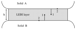
New enhanced constitutive law and failure criterion of the LEBIM, cf. [8, 21, 35], are introduced in this section. Although this interface model is originally considered representing an adhesive layer of a small thickness , it can be applied to simulate debonding mechanisms of bimaterial systems where, strictly speaking, there is no additional third material between bonded materials, as may occur in the present case of fibre-matrix interface in a real composite. Actually, the continuous distribution of springs in the LEBIM has zero thickness.
2.1 Constitutive law of the spring distribution
The constitutive law of the continuous spring distribution is defined by a relation between tractions and relative displacements at the interface, Fig. 1. When modeling an undamaged isotropic layer this spring distribution is governed by the following simple linear-elastic law written at an interface point , Fig. 1(a) and (b):
| (1) |
where and are the normal and tangential tractions at a point of the elastic layer, and are the normal (opening) and tangential (sliding) relative displacements between opposite interface points, and and denote the normal and tangential stiffnesses of the spring distribution, respectively.
Linear elastic - (perfectly) brittle interface
Broken interface
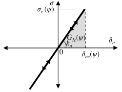
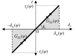
The failure criterion may be written in terms of the traction modulus at every point , . The interface breaks at a point when the traction modulus reaches its critical value:
| (2) |
where the critical normal and tangential tractions and , and the corresponding critical relative displacements and , are functions of the fracture-mode-mixity angle at a particular point . Thus, different critical values of these variables may be obtained at different interface points, due to the fact that can vary along the adhesive layer.
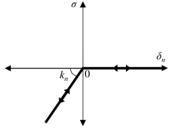
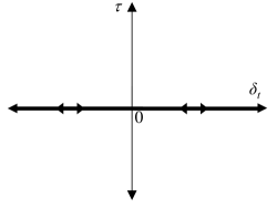
Once the failure criterion in (1), which will be described in the following section, is reached the damaged interface is considered free of stresses, unless contact appears between both sides of the damaged interface. In this case, the interface retains its normal stiffness. Therefore, once the interface is broken, the following non-linear constitutive law222Let us recall the definition of the positive and negative part of a real number used in the present work, . is also referred to as Macaulay brackets or ramp function. is considered at an interface point , Fig. 1(c) and (d):
| (3) |
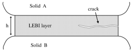
Regarding the normal linear elastic - (perfectly) brittle law, once a portion of interface is cracked, large negative values of the normal relative displacement, , are essentially avoided by using the frictionless contact condition (3), see Fig. 1(c). The use of an elastic frictionless contact is based on the idea that some portions of the cracked layer remain on the adjacent surfaces. Thus, when these surfaces enter in contact, it seems reasonable to assume that these portions of the layer could compress with the same stiffness in the normal direction as the layer had before cracking, see Fig. 2.
The stiffness parameters and could be related to the parameters of a linear elastic isotropic layer (Young’s modulus , Poisson’s ratio , shear modulus , Lame’s parameter , and a small thickness ) [8] by:
| (4) |
| (5) |
where and . From (4) and (5) the following expression of the ratio of and can be obtained:
| (6) |
leading to the following constraint for thin isotropic layers .
2.2 Interface failure criterion
The interface failure criterion is based on the Energy Release Rate (ERR) concept, although its final expression used in the computational implementation is given in terms of the interface tractions. As the LEBIM implies the absence of stress singularities at the crack tip, the ERR in a linear interface model is defined as the stored elastic strain energy per unit length in the unbroken “interface spring” at the crack tip (infinitesimal interface segment situated at the crack tip) [17, 20]. Thus, the ERR of a mixed mode crack in a linear elastic interface is defined as, cf. [8, 21]:
| (7) |
verifying for .
An extension of the energetic fracture-mode-mixity-angle , introduced in [8, 21] by the relation for , which will cover also an interface under compression with , can be defined by
| (8) |
where and , and being the stress and relative displacement based fracture-mode-mixity angles, respectively. Notice that for , and that absolute value of tangent of is given by the geometric mean of tangents of and , i.e. .
According to the interface failure criterion proposed in the present work, an interface point breaks when the ERR reaches the fracture energy (cf. Fig. 1(a) and (b)), which depends on the fracture mode mixity, i.e. . By a suitable modification of the phenomenological law , suggested in [37], the following general expressions of the critical values of interface normal and tangential tractions as well as of the normal and tangential relative displacements (shown in Fig. 1) as functions of the fracture-mode-mixity-angle are obtained, cf. [8, 35]:
| (9a) | |||||
| (9b) | |||||
where is the interface fracture toughness in pure mode I, is the critical interface normal stress in pure mode I (interface tensile strength) and is a fracture mode-sensitivity parameter obtained experimentally. A typical range characterizes interfaces with moderately strong fracture mode dependence [37].
It should be noticed that if and values are obtained experimentally, then is given by the relation . Thus, the LEBIM needs the input of four independent variables: , , and .
The plot of the interface failure curve parameterized by equations (9), in the plane of normalized interface stresses , considering , is shown in Fig. 3 where only the upper half of these curves is plotted for . According to Fig. 3, an interface failure under compressions is possible but requires larger shear stresses. As a consequence, a closed crack with compressions in the neighbourhood of the crack tip may propagate in presence of sufficiently large shear stresses.
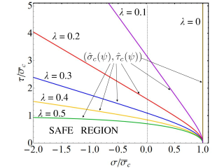
The interface failure curves for are open having two asymptotes whose angles are
| (10) |
and , see Fig. 3, an interface failure for these values of being only possible for . It is easy to see that is unbounded for approaching [8, 35, 37]. Notice that these interface failure curves are closed for , reducing to an ellipse for .
Failure (damage) of a portion of the interface layer is modeled as an abrupt decrease (jump down) of stresses in this zone of the layer, associated to a free separation or sliding of both interface surfaces, when a point on the failure curve (in plane) is achieved in that portion of the layer. Actually, in view of Fig. 1, in the interface portion under compression only shear stresses jump down after its failure.
3 Problem of a circular inclusion under biaxial transverse loads
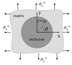
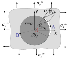
The plane strain problem of a circular inclusion of radius embedded in an infinite matrix, initially without any debond along its interface, and subjected to remote uniform stresses is considered. The materials of both the inclusion and matrix are considered to be linear elastic isotropic. Let and be the cartesian and polar coordinates with the origin of coordinates in the center of the inclusion, assuming without any loss of generality that is the principal coordinate system of the remote stress state defined by the principal stresses , see Fig. 4.
Although the ratio of the principal stresses is sometimes used to characterize the biaxiality of the remote stress state [10], in the present work, which covers also configurations where both remote principal stresses are compressive, the following general load-biaxiality parameter333It is easily to see that gives the position of the center of the normalized Mohr circumference and its characteristic values are - equibiaxial tension, - uniaxial tension, - equibiaxial tension-compression (pure shear stress), - uniaxial compression and - equibiaxial compression). It is useful to realize that .:
| (11) |
is more suitable. Denoting the Frobenius norm of the remote stress state by , we have and .
Let the position where the interface crack onset occurs be defined by the polar angle . The semidebond angle is denoted as . During the debond growth the angle may or may not be placed at the center of the debond.
According to Fig. 4(b) only one debond, initiated at a point A(, ), is considered, although depending on the problem symmetry two or four equivalent positions for debond onset may exist at the inclusion interface with , . Nevertheless, according to the experimental evidence only one side of the fibre-matrix interface is usually broken [2, 40]. This will also be obtained by the present numerical model in Section 5, where the crack onset can occur at any of these two or four points, but once a crack has started at one of these points it will continue growing, preventing failure in the other symmetrically situated points.
A typical bi-material system among fibre reinforced composite materials is chosen for this study: -epoxy matrix and -glass fibre (inclusion), the elastic properties of matrix and fibre being GPa, , GPa and , respectively. The corresponding Dundurs bi-material parameters in plane strain are and and the harmonic mean of the effective elasticity moduli is GPa, see [4, 7, 34, 41, 42] for their definitions.
The strength and fracture properties of the fibre-matrix interface, tensile strength MPa and fracture energy in mode I Jm-2, considered in the numerical procedure are in the range of values found in the literature [2, 3], and correspond to quite brittle behaviour [7, 10] making the hypothesis of the LEBIM to represent appropriately a possible real composite material behavior [8].
A dimensionless structural parameter, referred to as brittleness number, governing brittle-to-tough transition in the fibre-matrix debond onset can be defined following [7, 8, 10] as
| (12) |
where the second expression, showing that is given by the ratio of stiffnesses of the bimaterial () and interface () with the unique characteristic length of problem geometry (fibre diameter ), is obtained using the relation [8, 21]. Small values of (typically ) correspond to brittle and large values of (typically ) to tough configurations. Noteworthy is closely related to a similar dimensionless parameter defined by Lenci [17] for a crack of size at a weak interface, verifying .
In the following numerical study, some parametric analyses will be presented, all of them consider a default configuration with =0.25, =0.25 and a circular inclusion radius =7.5 m, leading to .
4 Analytical and numerical procedures applied
First, the analytical solution of the above defined problem of a circular inclusion (fibre) under remote biaxial transverse loads, considering the inclusion-matrix interface as a linear-elastic layer without any debond, is presented and discussed. Then based on this solution and the hypotheses of the LEBIM, an analytical procedure able to evaluate a failure curve and the angle where debond onset takes place is proposed. Finally a BEM model of this problem, able to analyse interface debond onset and propagation, is briefly described.
4.1 Analytical procedure applied to analyse the fibre-matrix debond onset
By using a closed-form expression of the Airy stress function deduced by Gao [25] for an elastic circular inclusion (fibre) embedded in an elastic infinite matrix with an undamaged interface, the following expressions of interface tractions can be obtained assuming uniform biaxial stresses, and , at infinity:
| (13a) | ||||
| (13b) | ||||
where
| (14a) | ||||
| (14b) | ||||
| (14c) | ||||
| (14d) | ||||
with , and and , respectively being, the shear modulus and Kolosoff constant of the matrix (), and analogously for the inclusion (). Equations (13) and (14) generalize expressions (27)-(31) introduced in [8]444There are several misprints in Eqs. (27)-(31) in [8]: in Eq. (28) the minus sign is missing and the term should be replaced by the missing term presented in (14d) herein, and the correct form of the term in Eq. (30) is given in (14b) herein. for the uniaxial loading case ().
Taking into account that the parameters , , and can be written in terms of , and the elastic properties of matrix and inclusion [8], and that due to (12), the interface tractions in (13) can be expressed in terms of dimensionless functions and as:
| (15a) | ||||
| (15b) | ||||
where (6), (11) and (12) are the governing dimensionless parameters.
Pseudocode of the proposed procedure for the evaluation of a failure curve in the plane of normalized remote stresses , which uses the above analytical solution for interface tractions and assumes the hypotheses of the LEBIM, is introduced in Fig. 5. Additionally, this procedure evaluates the polar angle where the debond initiates. The procedure is self-explaining, thus its detailed description is omitted for the sake of brevity.
Define
For Do
For Do
Evaluate and
[Eqs.(13)-(15)]
[Eq.(8)]
Evaluate [Eq.(10)]
If ( and ) or Then
Evaluate and [Eq.(9)]
[The critical load factor for ]
Else
[Debond is not allowed at ]
Endif
Endfor
and
and
Endfor
The procedure in Fig. 5 predicts the critical biaxial load for each given load biaxiality parameter leading to the failure of the first interface point. However, it may be not clear if this initial infinitesimal debond will further grows unstably under the same critical load or an additional increase of this load is required to keep the infinitesimal debond growing. This question will be answered applying a numerical procedure like that presented in the next section.
4.2 Numerical procedure applied to analyse the fibre-matrix debond onset and propagation
The present non-linear problem of the crack onset and propagation along the fibre-matrix interface governed by the LEBIM is solved by means of the BEM, which is very suitable for solving this kind of problems where all nonlinearities are placed on the boundaries of the subdomains. Implementation details of the collocational 2D BEM code employed and an overall description of the solution algorithm can be found in [8, 21, 35, 43]. This algorithm uses an incremental formulation and a very efficient solution procedure, usually referred to as sequentially linear analysis, appropriate for the present non-linear problem. The present BEM model represents a cylindrical inclusion with a radius 7.5 m inside a relatively large square matrix with side mm. BEM mesh has 1472 continuous linear boundary elements: two uniform meshes of 720 elements discretizing both sides of the fibre-matrix interface (therefore, the polar angle of each element is 0.5∘) and 32 elements for the external boundary of the matrix, where the remote stresses and are applied. Rigid body motions are removed by the Method F2 introduced in [44], see also [43]. The inclusion is considered initially as bonded to the matrix along its perimeter by means of a continuous distribution of springs governed by the LEBIM. The debond onset and propagation is modeled by progressively breaking springs between boundary element nodes placed at both sides of the interface. Thus, the numerical procedure used is driven by the interface crack length and is able to analyse both snap-through and snap-back instabilities of a crack growth.
5 Results for the fibre-matrix debond onset and propagation
The aim of this section is to study the influence of the governing parameters (6), (9), (11) and (12) of the present model on the debond onset and propagation in the case of the glass-fibre and epoxy-matrix composite (Section 3). Specifically, first, the debond onset is studied focusing in the angle of debond onset as a function of the remote stress biaxiality (Section 5.1) and by evaluating the failure curves in the plane of normalized remote stresses (Section 5.2). Then, debond growth is studied by evaluating load-debond opening curves and load-debond length curves (Section 5.3). Finally, an instability analysis of the debond onset and growth is introduced (Section 5.4). Both analytical and numerical procedures developed are applied wherever feasible, and their results are compared, which allows us to mutually verify the correctness of the formulation and implementation of these procedures. The analytical procedure is very suitable for some of the parametric studies presented, nevertheless its range of application is limited to the debond onset characterization in the present problem of a single fibre embedded in an infinite matrix. The scope of the numerical procedure developed is much wider and it will allow us to solve complex realistic problems of concurrent debond onset and propagation in dense fibre packing including random distribution of many fibres with different initial and boundary conditions (including contact conditions) in future, cf. [35, 36].
5.1 Position of the crack onset
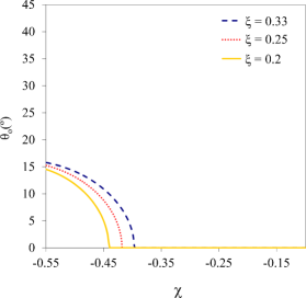
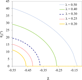
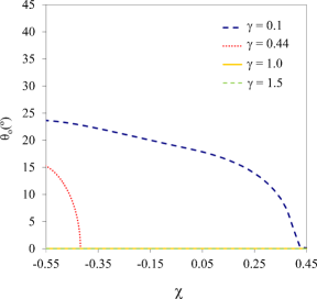
The position where the crack onset occurs, defined by the angle , Fig. 4, is studied by means of the analytic procedure introduced in Section 4.1. Plots of in Fig. 6 show the influence of different governing parameters on this angle. Notice that for (remote equibiaxial tension) all interface points are equivalent and is undetermined.
According to these plots of , a bifurcation takes place at a particular value of referred to as bifurcation value . For the first interface point breaks at in pure fracture mode I. This behaviour could be expected for tension dominated remote loads roughly characterized by , taking into account the distribution of interface tractions (13) and the failure criterion in Fig. 3. Nevertheless, as will be seen, there is an exception observed for very brittle configurations. For , a kind of bifurcation is observed due to a sudden variation of for below, and close, to . In this case, the interface breaks in a mixed mode.
The influence of on is depicted in Fig. 6(a), showing that with increasing value of the bifurcation value increases slightly as well. Nevertheless, it seems that for decreasing all curves tend to a similar value of .
Fig. 6(b) presents the influence of on , showing that with increasing value of the bifurcation value increases as well. Thus, for large values of a non-symmetric debond initiation is predicted for biaxial tension-compression loading, with tension being only a little lower than compression. For the value of increases with increasing value of , which could be expected, as the interface failure criterion becomes more sensitive to the interface shear traction value according to Fig. 3.
From Fig. 6(c), showing the influence of on , it can be observed that for higher values of no bifurcation takes place and , predicting the debond onset in mode I, for the considered values of , . However, for lower values of a non-symmetric debond is predicted for biaxial tension-compression loading even for relatively small values of compression load. Actually, it can be shown that for a low value of and a high value of , e.g. and , a non-symmetric debond initiation would be predicted even for the uniaxial tension. This somewhat surprising behaviour can be explained by the observation that the ratio of the maximum values of to in (13) is increasing for decreasing (and/or decreasing ) making easier the debond onset in mixed mode. It is remarkable that a similar behaviour for the uniaxial tension has also been observed in predictions by other models as CZM and FFM in [45].
5.2 Failure curves
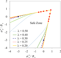
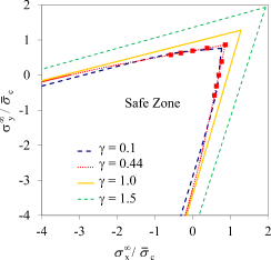
Fig. 7 presents failure curves parameterized by the load biaxiality parameter and representing the normalized critical remote stresses leading to the breakage of the first point (spring) of an initially undamaged inclusion-matrix interface. Analytical and numerical results are represented by continuous lines and marks, respectively. These plots show the influence of the material ( and ) and structural () dimensionless parameters of the problem on the failure curve shape and location.
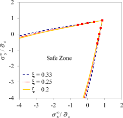
Regarding the influence of the load biaxiality parameter , it is easy to observe in all the plots in Fig. 7 that, considering (thus looking at the right-bottom branch of failure curves), for decreasing values of the critical remote stress decreases quite significantly. In particular, a relevant compression makes a debond onset easier, being significantly smaller than in the case of a tension or even in the case of the uniaxial tension () when .
The rather weak influence of the ratio of the interface stiffnesses on the fibre-matrix failure curve can be observed in Fig. 7(a) obtained by varying (=0.20, 0.25 and 0.33) and keeping constant the fracture mode-sensitivity parameter and the brittleness number =0.44. For lower values of the critical loads are only slightly lower, this influence being mostly visible for , and in particular for the case of the uniaxial compression ().
The influence of the fracture mode-sensitivity parameter on the failure curve is studied in Fig. 7(b), by varying (=0.2, 0.25, 0.3, 0.4 and 0.5) and keeping constant and . There is no influence of on the failure curve for , because in this range the crack onset occurs at , see Fig. 6(b), which, in view of the symmetry of the stress solution (13), means that shear tractions vanish there, and consequently the interface breaks in mode I at this point. Nevertheless, for larger values of compressions , i.e. , the crack onset changes its position given by , see Fig. 6(b), the interface the breaking in a mixed mode there. This leads to a strong influence of on the shape of failure curves for this range of , the critical loads being significantly lower for larger values of , because the interface strength strongly decreases with increasing according to (9) and Fig. 3.
The influence of the brittleness number on the failure curve is shown in Fig. 7(c), by varying (=0.1, 0.44, 1 and 1.5) and keeping constant and . While the variations of failure curves for small values of (brittle configurations) predicting small critical loads, are hardly visible, a quite strong influence of on the position of failure curves is observed for larger values of (tough configurations) predicting large critical loads. Notice that, in view of the dependence of on the inclusion radius (12), the variations of the failure curves with represent in fact a size effect of on the crack onset, cf. [7, 8, 10, 29].
As can be observed from Fig. 7, an excellent agreement is achieved between the analytical and numerical procedures for several tension dominated biaxial loads (with parameters , and ) and a uniaxial compression load (, and ). Recall that the present formulation of the LEBIM, see Fig. 3, allows studying also crack growth under compressions in presence of large shear tractions at the crack tip which are typically associated to contact between the crack faces in a zone adjacent to this tip. This capability allows us to model crack onset and growth even in the case of remote compressions applied in both directions, i.e. for .
As mentioned above, one of the reasons of larger differences between some failure curves shown in Fig. 7 are the variations of the crack onset position given by the angle .
5.3 Effect of the load biaxiality on the fibre-matrix debond onset and growth
The effect of the load biaxiality on the debond onset and growth is studied by the numerical procedure presented in Section 4.2. It will be shown that the failure curves presented in Fig. 7, referring to the breakage of the first interface point, actually represent the initiation of an unstable crack growth along the inclusion-matrix interface. The default values =0.25, =0.25 and =0.44 are chosen for the following numerical study.
In Fig. 8 and Table 1 the numerical results obtained for different values of the load biaxiality parameter and are presented. Recall that corresponds to the case of uniaxial tension in the -direction ().
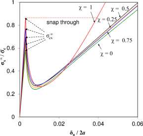
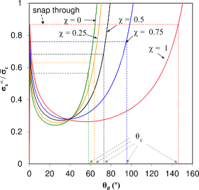
In Fig. 8(a), the normalized remote stress is plotted as a function of the normal relative displacement (opening), , evaluated at the point A defined in Fig. 4(b). The (minimum) remote stress value that is needed to initiate crack growth (in simple terms, the stress that is needed to break the first spring in the present discrete model of the interface) is called critical stress, , and corresponds to the local maximum of a function shown in Fig. 8(a). It can also be observed in Fig. 8(a) that after reaching the critical stress, , the crack growth becomes unstable, requiring smaller values of the remote tension to cause further crack growth. Thus, an instability phenomenon called snap-through is predicted in the case of external load or displacement control, see Section 5.4.
The variations of the local maxima values in Fig. 8(a) confirm the conclusion observed previously in Fig. 7 that the critical stress decreases with decreasing , see also Table 1.
In Fig. 8(b), the normalized remote stress is plotted versus the semidebond angle defined in Fig. 4(b). An estimation of the critical semidebond angle defined as the semidebond angle reached at the end of the initial unstable crack growth, keeping the remote stress constant, is also indicated in this figure. In general, increases with increasing in the range studied, see also Table 1. When , i.e. when significant remote tensions are applied in both axes, . Thus, an unstable debond growth is predicted along a very large portion of the fibre-matrix interface.
| 0 | 0.25 | 0.5 | 0.75 | 1 | |
|---|---|---|---|---|---|
| 0.573 | 0.629 | 0.692 | 0.769 | 0.864 | |
| (∘) | 58.25 | 63.25 | 72.75 | 95.25 | 146.0 |
Actually, the prediction of an unstable crack growth up to the critical semiangle is the key result obtained by the numerical solution of the present problem, as the values of and can also be obtained by the analytical procedure presented. An excellent agreement between the analytic and numerical results is remarkable.
5.4 Instability analysis of the fibre-matrix debond onset and growth
In the following section, the instability behaviour (snap-through) observed in Fig. 8 will be analysed in order to check why it may appear in an external load or displacement control. Although only the case of uniaxial tension , with the default values of , and , is considered for the sake of brevity, the results would be similar for other values of the governing dimensionless parameters. Fig. 9(a) shows the normalized applied remote stress versus the averaged longitudinal strain along the segments, and , between two pairs of points of the matrix placed on the -axis and symmetrically situated with respect to the origin. The coordinates of the end points of are and of , where is the fibre radius and the half-length of the matrix square cell side, in the present study. represents the averaged longitudinal strain for a purely linearly elastic fibre-matrix interface with no debond, while is the additional averaged longitudinal strain due to debond . For a similar additive decomposition of relative displacements, see [46] (Ch. 12 therein).
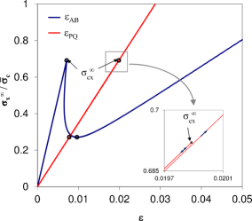
The diagrams in both cases (considering segments and ) exhibit cusp snapback instability [47] after the peak point (bifurcation point) where the debond onset occurs. Actually, this kind of instability also appears for all intermediate segments between and . While the snapback instability is easily observable in the curve in Fig. 9(a), this instability is not visible by naked-eye in the curve , as the curve branches before and after the peak point are extremely close to each other, visually coinciding in the plot, because the matrix cell is very large with respect to the fibre. As the effect of the debond onset and growth on the fibre-matrix interface is hardly visible on this plot, a zoomed view of this curve with its cusp is also included in Fig. 9(a) to show this instability behaviour. Obviously the values of at the local maxima (peak point) and minima in both curves coincide (values 0.692 and 0.2704, respectively) as indicated in the curve plots. It means that after the debond onset, we may decrease the applied load significantly, up to 39% of the critical load in the peak, keeping a continuous propagation of the debond.
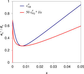
Moreover, to understand better the post-peak behaviour, diagrams are plotted in Fig. 9(b). The value of , which strongly depends on the cell size (as a consequence of the Saint-Venant and superposition principles), is scaled by an arbitrary factor resulting in a value very similar to that of . The initial very steep negative slope of these diagrams indicates that according to the present model, using the LEBIM of the fibre-matrix interface, the debond onset and growth exhibits cusp snapback instability typical for a brittle structural behaviour. This observation is quite different from a smooth snapback instability observed in some cases in [29, 45] using a CZM of the fibre-matrix interface.
Summarizing the above analysis, the curve shows that under both load and displacement control at the outer boundaries of the matrix cell a sudden and large breakage of the fibre-matrix interface is predicted by the present model. Notice that, the debond onset and growth could develop, at least hypothetically, in a stable manner if it would be controlled by the crack opening according to Fig. 8(a).
6 Concluding remarks
A new linear elastic - (perfectly) brittle interface model (LEBIM) has been used to characterize the onset and growth of the debond at a single fibre embedded in an infinite matrix subjected to biaxial transverse loads , Fig. 4. Both analytic and numerical procedures have been devised and exploited to study this problem. The analytic procedure has been used in the parametric studies regarding debond onset and for testing the numerical procedure implemented in a collocation BEM code, whereas the numerical procedure is quite general and is currently applied to the numerical analysis of debond onset and growth in dense fibre packing representing a portion of a real unidirectional composite lamina, with several fibres, under biaxial transverse loads [36].
A comprehensive parametric study of this single-fibre debond problem analysing the influence of all the dimensionless parameters governing the problem: - load biaxiality (11), - ratio of the interface shear and normal stiffnesses (6), - sensitivity to interface fracture mode mixity (9), and - brittleness number (12), in addition to the elastic properties of fibre and matrix, has been carried out. To the best knowledge of the authors no similar parametric study has been presented before neither for the LEBIM nor CZMs.
Using a general analytical solution for tractions at the undamaged linear-elastic fibre-matrix interface under uniform far-field biaxial transverse stresses and assuming the LEBIM, quite universal failure curves in the plane of normalized far-field stresses , where is the interface tensile strength, have been generated. These curves, parameterized by , depend only on a few dimensionless parameters , , , and , and . In particular, the elastic properties , , and corresponding to a glass-epoxy composite have been considered. It can be observed from these curves, that with decreasing the critical load decreases as well, i.e. a compression makes easier crack onset leading to a lower critical tension load , and viceversa a tension difficulties crack onset leading to a larger value of . These observations agree with previous experimental results in [9].
The debond onset angles associated to these failure curves have also been evaluated analytically. A bifurcation from the zero value of , predicting a debond onset in mixed mode, typically occurs for a magnitud of the compression load larger than the tension load , i.e. for . Nevertheless, in very brittle configurations characterized by such a bifurcation can occur for small or vanishing values of .
The observed influence of the governing dimensionless parameters on the shape and location of the failure curves and the debond onset angle is summarized in the following: a) has only a slight influence on the shape and no influence on the position of the failure curves, also its influence on is quite small; b) typically has no influence on the debond onset for tension dominated loads as the interface breaks at under pure mode I (except for very brittle configurations with ), but it has a quite relevant influence on , in particular on its bifurcation point position, for compression dominated loads, consequently shows some influence on the shape of failure curves for such loads, particularly for ; c) has a strong influence on the position of failure curves for tough configurations , while for brittle configurations its influence on the position of failure curves is rather weak showing, however, some influence on their shape. The influence of on is quite relevant for .
From the numerical results obtained, it can be observed that when the remote load reaches its critical value given by , the subsequent debond growth up to the critical semidebond angle is unstable, an instability phenomenon called snap-back taking place. A parametric study shows that increases with increasing in the range studied, eventually very large debonds with are predicted when similar tensions are applied in both directions.
From the above analytical and numerical results it appears that the new LEBIM formulation introduced adequately describes the behavior of the fibre-matrix system, predicting expected behaviour where some experimental results are available [9] and also being in a quite good agrement with other analytical and numerical studies [4, 5, 6, 10, 11, 45]. An important novelty with respect to the previous LEBIM formulations in [8, 21] is that the new formulation is able to model interface crack onset and growth in presence of compressive interface tractions, in particular when the crack is closed with crack faces in frictionless contact.
It has been shown that the present LEBIM implementation in a BEM code is an efficient computational tool for an interface crack onset and mixed mode crack growth modeling. This tool can be useful not only for an analysis of fibre-matrix debonding under biaxial transverse loads as carried out in the present work and in [36], but also in other problems as interlaminar fracture toughness tests of symmetric and non-symmetric laminates and delaminations in cross-ply laminates.
Acknowledgements
The work was supported by the Junta de Andalucía (Projects of Excellence TEP-1207, TEP-2045 and TEP-4051), the Spanish Ministry of Education and Science (Projects TRA2006-08077 and MAT2009-14022) and Spanish Ministry of Economy and Competitiveness (Projects MAT2012-37387 and DPI2012-37187).
References
- Hull and Clyne [1996] Hull D, Clyne T. An Introduction to Composite Materials. Cambridge University Press; 2 ed.; 1996.
- Zhang et al. [1997] Zhang H, Ericson M, Varna J, Berglund L. Transverse single-fiber test for interfacial debonding in composites: 1. Experimental observations. Composites Part A: Applied Science and Manufacturing 1997;28A:309 –15.
- Varna et al. [1997] Varna J, Berglund L, Ericson M. Transverse single fiber test for interfacial debonding in composites 2: Modelling. Composites Part A: Applied Science and Manufacturing 1997;28:317–26.
- París et al. [2007] París F, Correa E, Mantič V. Kinking of transverse interface cracks between fiber and matrix. Journal of Applied Mechanics 2007;74:703–16.
- Correa et al. [2008a] Correa E, Mantič V, París F. Numerical characterisation of the fibre-matrix interface crack growth in composites under transverse compression. Engineering Fracture Mechanics 2008a;75:4085–103.
- Correa et al. [2008b] Correa E, Mantič V, París F. A micromechanical view of inter-fibre failure of composite materials under compression transverse to the fibres. Composites Science and Technology 2008b;68:2010–21.
- Mantič [2009] Mantič V. Interface crack onset at a circular cylindrical inclusion under a remote transverse tension. Application of a coupled stress and energy criterion. International Journal of Solids and Structures 2009;46:1287–304.
- Távara et al. [2011] Távara L, Mantič V, Graciani E, París F. BEM analysis of crack onset and propagation along fiber-matrix interface under transverse tension using a linear elastic-brittle interface model. Engineering Analysis with Boundary Elements 2011;35:207–22.
- París et al. [2003] París F, Correa E, Cañas J. Micromechanical view of failure of the matrix in fibrous composite materials. Composites Science and Technology 2003;63:1041–52.
- Mantič and García [2012] Mantič V, García I. Crack onset and growth at the fibre-matrix interface under remote biaxial transverse loads. Application of a coupled stress and energy criterion. International Journal of Solids and Structures 2012;49:2273–90.
- Correa et al. [2013] Correa E, París F, Mantič V. Effect of the presence of a secondary transverse load on the inter-fibre failure under tension. Engineering Fracture Mechanics 2013;doi:“bibinfo–doi˝–10.1016/j.engfracmech.2013.02.026˝.
- Goland and Reissner [1944] Goland M, Reissner E. The stresses in cemented joints. Journal of Applied Mechanics 1944;11:A17–27.
- Erdogan [1997] Erdogan F. Fracture mechanics of interfaces, In: Damage and Failure of Interfaces. Balkema Publishers: Rotterdam; 1997.
- Geymonat et al. [1999] Geymonat G, Krasucki F, Lenci S. Mathematical analysis of a bonded joint with a soft thin adhesive. Mathematics and Mechanics of Solids 1999;4:201–25.
- Benveniste and Miloh [2001] Benveniste Y, Miloh T. Imperfect soft and stiff interfaces in two-dimensional elasticity. Mech Mater 2001;33:309–23.
- Hashin [2002] Hashin Z. Thin interphase/imperfect interface in elasticity with application to coated fiber composites. Journal of the Mechanics and Physics of Solids 2002;50:2509–37.
- Lenci [2001] Lenci S. Analysis of a crack at a weak interface. International Journal of Fracture 2001;108:275–90.
- Caporale et al. [2006] Caporale A, Luciano R, Sacco E. Micromechanical analysis of interfacial debonding in unidirectional fiber-reinforced composites. Computers & Structures 2006;84:2200–11.
- Bennati et al. [2009] Bennati S, Colleluori M, Corigliano D, Valvo P. An enhanced beam-theory model of the asymmetric double cantilever beam (ADCB) test for composite laminates. Composites Science and Technology 2009;69:1735 –45.
- Carpinteri et al. [2009] Carpinteri A, Cornetti P, Pugno N. Edge debonding in FRP strengthened beams: Stress versus energy failure criteria. Engineering Structures 2009;31:2436–47.
- Távara et al. [2010] Távara L, Mantič V, Graciani E, Cañas J, París F. Analysis of a crack in a thin adhesive layer between orthotropic materials. An application to composite interlaminar fracture toughness test. Computer Modeling in Engineering and Sciences 2010;58(3):247–70.
- Cornetti et al. [2012] Cornetti P, Mantič V, Carpinteri A. Finite Fracture Mechanics at elastic interfaces. International Journal of Solids and Structures 2012;49:1022 –32.
- Weißgraeber and Becker [2013] Weißgraeber P, Becker W. Finite Fracture Mechanics model for mixed mode fracture in adhesive joints. International Journal of Solids and Structures 2013;50:2383 –94.
- Valoroso and Champaney [2006] Valoroso N, Champaney L. A damage-mechanics-based approach for modelling decohesion in adhesively bonded assemblies. Engineering Fracture Mechanics 2006;73:2774 –801.
- Gao [1995] Gao Z. A circular inclusion with imperfect interface: Eshelby’s tensor and related problems. Journal of Applied Mechanics 1995;62:860–6.
- Bigoni et al. [1998] Bigoni D, Serkov S, Valentini M, Movchan A. Asymptotic models of dilute composites with imperfectly bonded inclusions. International Journal of Solids and Structures 1998;35:3239–58.
- Mogilevskaya and Crouch [2002] Mogilevskaya S, Crouch S. A Galerkin boundary integral method for multiple circular elastic inclusions with homogeneously imperfect interfaces. International Journal of Solids and Structures 2002;39:4723–46.
- Xie and Levy [2007] Xie M, Levy A. Defect propagation at a circular interface. International Journal of Fracture 2007;144:1–20.
- Carpinteri et al. [2005] Carpinteri A, Paggi M, Zavarise G. Snap-back instability in micro-structured composites and its connection with superplasticity. Strength, Fracture and Complexity 2005;3:61– 72.
- Han et al. [2006] Han R, Ingber M, Schreyer H. Progression of failure in fiber-reinforced materials. Computers Materials & Continua 2006;4:163–76.
- Ngo et al. [2010] Ngo D, Park K, Paulino G, Huang Y. On the constitutive relation of materials with microstructure using a potential-based cohesive model for interface interaction. Engineerign Fracture Mechanics 2010;77:1153–74.
- Kushch et al. [2011] Kushch V, Shmegera S, Brøndsted P, Mishnaevsky L. Numerical simulation of progressive debonding in fiber reinforced composite under transverse loading. International Journal of Engineering Science 2011;49:17 –29.
- Leguillon [2002] Leguillon D. Strength or toughness? A criterion for crack onset at a notch. European Journal of Mechanics A/Solids 2002;21:61–72.
- Mantič et al. [2006] Mantič V, Blázquez A, Correa E, París F. Analysis of interface cracks with contact in composites by 2D BEM. In: Guagliano M, Aliabadi MH, editors. Fracture and Damage of Composites. WIT Press, Southampton; 2006, p. 189–248.
- Távara [2010] Távara L. Damage initiation and propagation in composite materials. Boundary element analysis using weak interface and cohesive zone models. PhD Thesis; Universidad de Sevilla: Sevilla; 2010.
- Távara et al. [2013] Távara L, Mantič V, Graciani E, París F. BEM modelling of interface cracks in a group of fibres under biaxial transverse loads. In: Sellier A, Aliabadi MH, editors. Advances in Boundary Element Techniques XIV, Proceedings of the 14th International Conference Paris, France. EC Ltd, Eastleight, UK; 2013,.
- Hutchinson and Suo [1992] Hutchinson J, Suo Z. Mixed mode cracking in layered materials; vol. 29 of Advances in Applied Mechanics. Academic Press: New York; 1992.
- Lemaitre and Desmorat [2005] Lemaitre J, Desmorat R. Engineering Damage Mechanics. Springer-Verlag: Berlin; 2005.
- Bialas and Mróz [2005] Bialas M, Mróz Z. Damage modelling at material interfaces. In: Sadowski T, editor. Multiscale Modelling of Damage and Fracture Processes in Composite Materials. Springer, Wien; 2005, p. 213–70.
- Correa et al. [2007] Correa E, Gamstedt EK, París F, Mantič V. Effects of the presence of compression in transverse cyclic loading on fibre–matrix debonding in unidirectional composite plies. Composites Part A: Applied Science and Manufacturing 2007;38:2260 –9.
- Soden et al. [1998] Soden P, Hintonb M, Kaddour A. Lamina properties, lay-up configurations and loading conditions for a range of fibre-reinforced composite laminates. Composites Science and Technology 1998;58:1011–22.
- Fiedler et al. [2001] Fiedler B, Hojo M, Ochiai S, Schulte K, Ando M. Failure behavior of an epoxy matrix under different kinds of static loading. Composites Science and Technology 2001;61:1615–24.
- Graciani et al. [2005] Graciani E, Mantič V, París F, Blázquez A. Weak formulation of axi-symmetric frictionless contact problems with boundary elements: Application to interface cracks. Computer and Structures 2005;83:836–55.
- Blázquez et al. [1996] Blázquez A, Mantič V, París F, Cañas J. On the removal of rigid body motions in the solution of elastostatic problems by direct BEM. International Journal for Numerical Methods in Engineering 1996;39:4021–38.
- Paggi et al. [2013] Paggi M, García I, Mantič V. Fiber-size effects on the onset of fiber-matrix debonding under transverse tension: A comparison between cohesive zone and finite fracture mechanics models. Engineering Fracture Mechanics 2013;(submitted).
- Bažant and Cedolin [1991] Bažant Z, Cedolin L. Stability of Structures Elastic, Inelastic, Fracture and Damage Theories. Oxford University Press: New York; 1991.
- Carpinteri [1989] Carpinteri A. Cusp catastrophe interpretation of fracture instability. Journal of the Mechanics and Physics of Solids 1989;37:567–82.