Interaction of laser-cooled 87Rb atoms with higher order modes of an optical nanofibre
Ravi Kumar1,2, Vandna Gokhroo1, Kieran Deasy1, Aili Maimaiti1,2, Mary C. Frawley1,2, Ciarán Phelan1 and Síle Nic Chormaic1,∗
1Light-Matter Interactions Unit, OIST Graduate University, Onna-son, Okinawa 904-0495, Japan
2Physics Department, University College Cork, Cork, Ireland
∗sile.nicchormaic@oist.jp
Abstract: Optical nanofibres are used to confine light to subwavelength regions and are very promising tools for the development of optical fibre-based quantum networks using cold, neutral atoms. To date, experimental studies on atoms near nanofibres have focussed on fundamental fibre mode interactions. In this work, we demonstrate the integration of a few-mode optical nanofibre into a magneto-optical trap for 87Rb atoms. The nanofibre, with a waist diameter of 700 nm, supports both the fundamental and first group of higher order modes and is used for atomic fluorescence and absorption studies. In general, light propagating in higher order fibre modes has a greater evanescent field extension around the waist in comparison with the fundamental mode. By exploiting this behaviour, we demonstrate that the detected signal of fluorescent photons emitted from a cloud of cold atoms centred at the nanofibre waist is larger (6 times) when higher order guided modes are considered as compared to the fundamental mode. Absorption of on-resonance, higher order mode probe light by the laser-cooled atoms is also observed. These advances should facilitate the realisation of atom trapping schemes based on higher order mode interference.
1 Introduction
Subwavelength diameter optical fibres, commonly known as “optical nanofibres (ONFs)”, are proving to be of immense value for both fundamental and applied research with many different systems being investigated, such as cold atom manipulation and trapping [1, 2, 3, 4, 5, 6], colloidal particle manipulation [7, 8, 9], and sensing [10, 11]. ONFs have a large evanescent field extension outside their waist region, making them ideal for light-matter interactions studies. The integration of ONFs into atomic systems has been a focus of ever increasing research interest in recent years [12]. Earlier experiments, such as those reported in [1, 2, 3, 4, 5], focussed on (i) the interaction of the light guided in the fundamental fibre mode, HE11, with atoms, or (ii) excitation of the HE11 mode through fluorescence coupling from resonantly excited atoms. While the latter experimental technique provides a means of characterizing the atoms near the surface of the optical nanofibre [1, 13, 14, 15], the former permits scenarios whereby atoms can be trapped around the optical nanofibre when far-detuned light is coupled into it [2, 3, 5]. Such ONFs can be termed as single-mode ONFs (SM-ONFs) since only the fundamental guided mode is supported [16]. The advantage of such a system is that, in addition to atom trapping applications, the nanofibre provides an optical interface that may be exploited for quantum communication using ensembles of laser-cooled atoms [6].
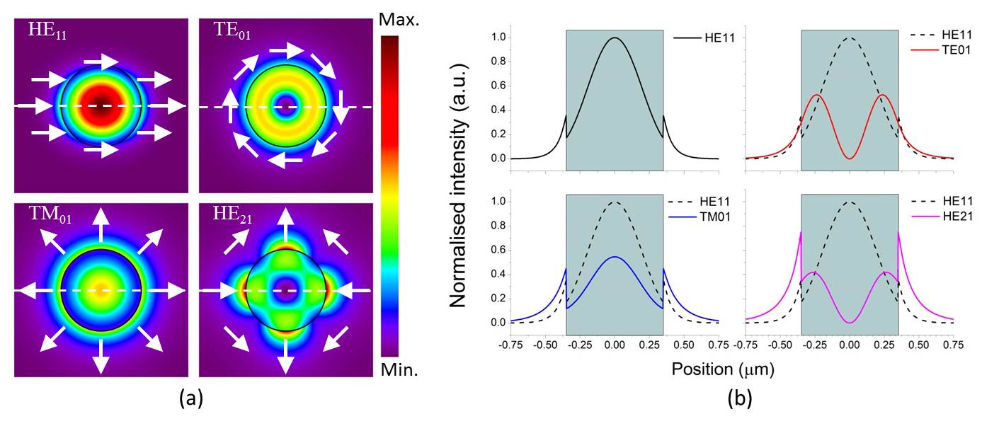
Other atom trapping geometries based on the use of higher order modes (HOMs) in a nanofibre have been proposed, permitting greater flexibility of atom position relative to the fibre and relative to other trapped atoms [17, 18, 19]. These schemes have the benefit of allowing for selective mode interference by adjusting the trapping parameters according to experimental requirements. Efficient guiding of HOMs in ONFs was a major technical challenge until our recent reporting of low-loss mode propagation in nanofibres fabricated from 80 m diameter silica fibre [20]. Similar work using 50 m fibre has since been reported [21]. We term such fibres few-mode ONFs (FM-ONFs) to distinguish them from the more conventional SM-ONFs. The crucial step in advancing such experiments was the result of a thorough study of the ideal parameters for fibre tapering, which revealed that reducing the fibre cladding-to-core diameter ratio relaxes the adiabatic criteria, thereby promoting efficient guiding of higher order modes [22]. The subsequent experimental achievements opened up a plethora of potential atom trapping scenarios, taking advantage of the few mode behaviour of the nanofibre. If one considers the field distribution of the first four true nanofibre modes (illustrated in Fig. 1), it is evident that the evanescent field for TE01, TM01 and HE21 extends further into the surrounding medium than for HE11. For a nanofibre of diameter 700 nm, as used for the experiments reported in this work, the fraction of light outside the nanofibre is higher for each of the TE01, TM01 and HE21 modes as compared with HE11. This phenomenon results in the evanescent light field for the higher order modes interacting with more atoms in the surrounding cloud than when studies are limited to the fundamental mode.
In this work, we present the first demonstration of a few-mode ONF integrated into a cloud of laser-cooled 87Rb atoms. The higher order modes in the ONF were maintained despite the integration of the nanofibre into the ultra high vacuum system. We use the FM-ONF for two different studies to contrast the difference between the higher and fundamental modes: (i) we consider the count rate of atomic fluorescence coupled into the fibre through the nanofibre waist for both fundamental and higher modes, and (ii) we measure the atomic absorption of an on-resonance probe guided in the fundamental or in the higher modes. We show that the count rates for photons coupled into the nanofibre are larger when we consider higher order guided modes than for the fundamental mode. This is in qualitative agreement with earlier theoretical predictions [23, 24]. Note that the theory is based on single atom coupling to the nanofibre, whereas our system involves multiple atoms. Our studies also show that more atoms absorb light from the evanescent field when higher order modes are used, leading to better absorption signals (measured as a percentage of the probe light sent through the nanofibre). Aside from the impact this work will have on trapping schemes for cold atoms, it is also expected to drive progress in several other areas of research including optical communication, neutral-atom based quantum networks, particle manipulation, and sensing.
This paper is organised as follows. Section 2 describes the fabrication of the FM-ONF and the experimental details of the magneto-optical trap for 87Rb. Section 3 presents the methods and results we obtained for three different experiments: (i) coupling of light (from MOT beams) to the nanofibre in the absence of an atom cloud, (ii) coupling of light to the nanofibre in the presence of an atom cloud, and (iii) absorption of a nanofibre-guided, probe beam by the laser-cooled atoms. The conclusion is presented in Section 4.
2 Experiment
2.1 Higher order mode optical nanofibre
Most published work on ONFs and atoms has focussed on SM-ONFs. Here, we used a FM-ONF which was fabricated from an 80 m diameter, commercial, few-mode fibre for 780 nm (SM1250G80, Thorlabs) using the heat-and-pull technique, as previously described in [20]. We use 80 m fibre in these experiments since it is easy to integrate with other fibre components using standard splicing techniques. The fibre pulling rig used was a hydrogen-oxygen flame-brushed system [25]. A 2 cm length of protective jacket was removed from the fibre and the two pigtails were clamped on translation stages on the pulling rig. The flame heated the fibre near to its phase transition temperature (). The flame was brushed along the fibre for a particular set length (the “hot zone”) while the fibre was simultaneously pulled by two translational stages moving in opposite directions with a constant speed (the “pulling speed”). The obtained taper profile was very close to exponential in the taper regions. Higher order mode propagation is extremely sensitive to the taper angle, which itself depends on the pulling speed and hot zone. A longer hot zone facilitates shallower exponential tapers, leading to a higher transmission, but this also elongates the taper length. If the nanofibre is too long, it is not suitable for integration into our cold atom setup. For these reasons, and in order to achieve reasonably high transmission of the higher order modes through the nanofibre, an optimal hot zone of 7.7 mm and tapering speed of 0.125 mm/s were used. A photodetector and a charged coupled device (CCD) camera were placed at the output of the fibre to monitor the transmission and mode profile during the tapering process.
Light propagating in the linearly polarised, LP11, approximate mode in the non-tapered fibre segments must be described by the the TE01, TM01 and HE21 true modes in the nanofibre region, and LP01 has its equivalence as the HE11 mode. For ease of notation, in the following discussions, we refer to the LP11 approximate mode for indicating the family of true modes collectively, while recognising that the true modes provide us with the correct solutions. Solving Maxwell’s equations for an optical fibre [26] yields a waveguide mode parameter, called the V-number, from which the number of modes supported by the fibre can be obtained. The V-number is given as
| (1) |
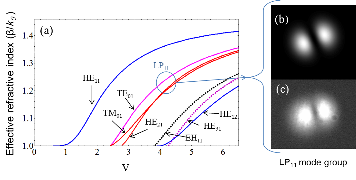
where is the radius of the core, is the wavelength of the light propagating in the fibre, and ncore and nclad are the refractive indices of the core and the cladding, respectively. The V-number for the specific fibre used in our experiments (when untapered) is 4.3, implying that it can support four linearly polarised mode groups, LP01, LP11, LP21, and LP02, for 780 nm light. When a nanofibre is fabricated, the cladding of the untapered fibre becomes the core for the nanofibre and the surrounding medium (e.g. air or vacuum) becomes the cladding. The V-number plot is shown in Fig. 2. The mode cutoff diameter is around 660 nm for the degenerate HE21 true modes and around 580 nm for both the TE01 and TM01 true modes.
In our experiments, the LP11 mode was excited by injecting a Laguerre-Gaussian (LG) beam into the untapered fibre pigtails [27]. A liquid-crystal-on-silicon spatial light modulator (Holoeye Pluto SLM) was used to create the LG beam [28]. A computer-generated vortex hologram was applied to the SLM and a vertically polarised, 780 nm laser beam was launched on to the SLM surface; the reflected beam formed a doughnut shape at the far field. This LG01 free space beam was coupled to the fibre to excite the LP11 mode which yielded a two-lobed beam profile at the fibre output, as expected. Along with the excitation of the LP11 mode, there was a small percentage of residual fundamental mode coupled into the fibre. This was mainly due to the purity of the generated LG beam and the efficiency of the fibre coupling. The level of the impurity was estimated by sending an LG01 beam into the fibre during the tapering process and observing its transmission as a function of pulling distance (see Fig. 3(a)). The mode cutoff pull length for the higher modes (HE21, TE01, TM01) and the fundamental mode can be defined from Fig. 3(a). Deducting the percentage of the remaining fundamental mode (Position 3) from the total intensity (Position 1), we estimated that the LP11 mode was excited in the few-mode fibre with a purity of 95%.
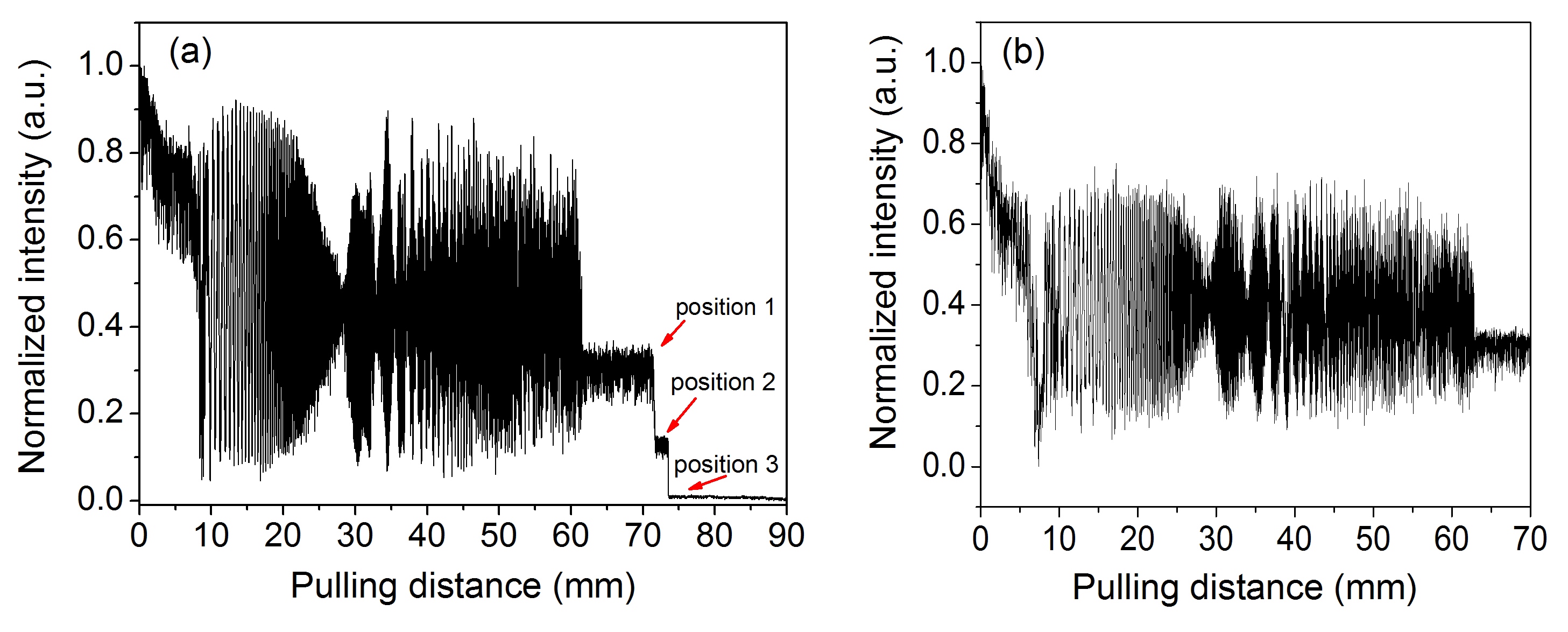
First, a nanofibre was fabricated using a 90 mm pulling length in order to obtain a complete transmission profile including mode cutoffs. The transmission graph (Fig. 3(a)) suggested that the pulling distance should be between 62 and 71 mm to obtain a nanofibre supporting the LP11 family of modes and the fundamental mode (Ref. [20] gives the details of the process). Since a smaller diameter fibre yields greater extension of the evanescent field into the surrounding medium, it is preferable to use a longer pulling length. For all other experiments reported here, we used a 70 mm pulling length to fabricate the nanofibre. This corresponded to 700 nm waist diameter determined from the calibration data of our pulling rig. Monitoring the mode profile until the end of the pulling process ensured that the prepared fibre still supported the LP11 mode. The nanofibre had 32% transmission for the LP11 mode group (see Fig. 3). The rest of the power was lost as it coupled to the cladding modes in the taper regions [29]. This fibre was highly adiabatic for the fundamental mode with 92% transmission. Using these values of total transmissions (and assuming both sides of the taper were equivalent as verified by measurement), we estimate that 96% of the input power was transmitted to the nanofibre waist for the fundamental mode and 56% for the LP11 mode group.
The nanofibre was glued to a U-shaped mount and installed vertically in an octagonal vacuum chamber used for the magneto-optical trap (MOT). The six cooling beams intersected at the nanofibre waist, four at 45∘ and two at 90∘ to the nanofibre axis. The fibre pigtails at either end of the nanofibre were passed through Teflon ferrules (with hand-drilled holes of 0.25 mm diameter) located on the top and the bottom flanges of the chamber. The ferrules were rendered vacuum tight by compressing Swagelok connectors [30]. A relatively simple experiment was carried out in order to test whether the distribution of power between the fundamental and the LP11 modes was affected by pressure on the tapered fibre via the Teflon ferrule. As described earlier, an LG01 mode was coupled to the fibre and the output was measured with a CCD camera. We observed minimal mode mixing as the ferrule was tightened. Note that it is crucial to keep the nanofibre straight to ensure minimal bending loss and distortion of the mode profiles of the light passing through it.
2.2 Magneto-optical trapping of atoms
87Rb atoms were cooled and trapped using a standard magneto-optical trapping technique (for details see [15] though it was for 85Rb). Base pressure in the vacuum chamber was 210-9 mbar and, when a current of 5 A was passed through a Rb dispenser, the pressure rose to 410-9 mbar and remained stable during the experiments.
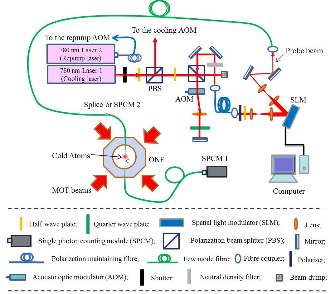
A 780 nm laser was locked to the 5 5 crossover peak of 87Rb for the cooling beam. The frequency was further shifted by an acousto-optical modulator (AOM) in a double-pass configuration so that it was 14 MHz red-detuned from the cooling transition, 5 5 . The cooling beam was split into four beams, two of which were retro-reflected to get three pairs of and beams for the MOT. Another laser, used as the repump, was locked to the 5 5 peak and shifted to the repump transition, 5 5 , using an AOM. The repump was overlapped with one of the cooling beams using a beam splitter. The magnetic field for the MOT was created by a pair of coils carrying equal currents of 3.5 A in opposite directions to generate a field gradient of 10 G/cm at the centre of the vacuum chamber. Each cooling beam had an intensity of 6 mW/cm2 and a diameter of 18 mm. The cold atoms were trapped around the waist of the FM-ONF. A compensation coil was used to generate a small magnetic field in the transverse direction to the MOT coils’ axis in order to optimise the overlap between the centre of the atom cloud and the nanofibre. The diameter of the cloud was 1 mm and there were 3106 atoms in the trap. The temperature of the cloud was measured to be 150 K by taking a series of fluorescence images of the cloud for different expansion times.
3 Measurements and results
3.1 Coupling of MOT beams to the nanofibre
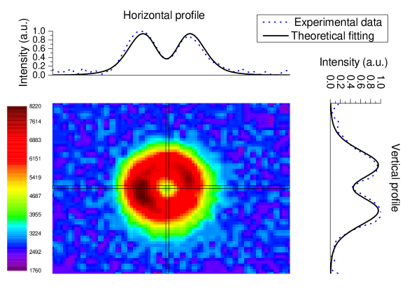
As a first test, in the absence of cold atoms and probe light through the FM-ONF, an analysis of MOT beam coupling to the nanofibre was conducted. The mode profile of the coupled light was analysed at the output of one of the FM-ONF pigtails by focussing it onto a CCD camera (replacing the SPCM by a CCD camera, in Fig. 4 ). The observed profile, as shown in Fig. 5, was doughnut shaped, but not completely dark at the centre. A fit of the observed intensity profiles using a combination of the LG00 and LG01 modes (where the LG00 mode corresponds to the LP01 fibre mode and the LG01 mode to the LP11 fibre mode) revealed that 55% of the light coming out from the nanofibre pigtail was in LG01. Taking the transmission difference for the fundamental and the higher modes through the FM-ONF into consideration, we estimate that 67% of the light from the MOT beams that coupled into the nanofibre excited higher order modes.
3.2 Fluorescence measurements
.
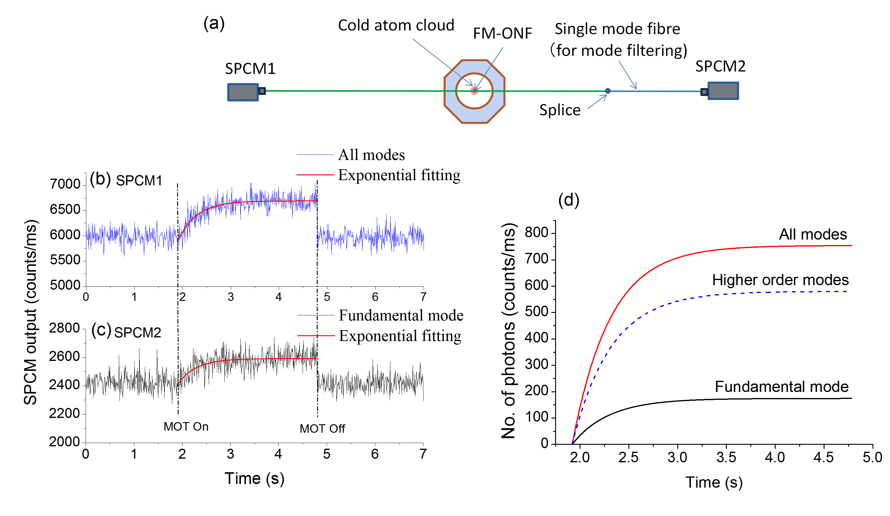
Next, we looked at the fluorescence coupling into the FM-ONF from resonantly-excited atoms. The cold atom cloud was formed around the waist of the FM-ONF and both the output pigtails were connected to single photon counting modules (SPCMs). In this condition, light coupled into the nanofibre had a contribution from (i) the MOT beams and (ii) the atomic fluorescence. Photon counts were recorded on both the SPCMs and the signals were found to be equivalent, i.e. half of the photons coupled in to the nanofibre travelled in each direction. In order to estimate the contribution of the fundamental mode to the total photon count rate, one output pigtail was spliced to a section of single mode fibre (SMF, 780HP, Thorlabs). The SMF acted as a filter for any higher order mode propagation (Fig. 6 (a)) and only fundamental mode guiding survived. Simultaneously, the second SPCM recorded the total number of photons coupled into all the fibre modes, i.e. both the fundamental and higher orders, collectively. The MOT magnetic field was switched on and off at intervals of few seconds (to provide enough time for the cloud to reach steady state) in order to separate the photon count contribution from the atom cloud (as shown in Figs. 6 (b) and (c)) and that arising from the MOT beams. By comparing the total photon signal with that obtained for only the fundamental mode, we determined that 85% of the atomic fluorescence coupling to the nanofibre was coupled into the higher order modes. In other words, for every photon coupled into the fundamental mode, approximately six photons coupled into the higher fibre modes. Note that the different transmissions from the waist to the pigtail output for the fundamental mode (96%) versus the higher order modes (56%) were taken into consideration.
In order to confirm this result, the same test was repeated with a different method for filtering out the higher order modes contribution. A SM-ONF was spliced to the output pigtail of the FM-ONF in place of the mode filtering SMF. The SM-ONF was fabricated from the same few-mode fibre (SM1250G80) as the nanofibre in the chamber. Similar results were obtained (data not shown).
3.3 Absorption measurements
Next, we considered atom absorption of the light in the evanescent field to see how it varied depending on whether higher order modes or the fundamental mode were guided by the nanofibre. A fraction of the cooling laser beam was passed through a double-pass AOM so that its detuning could be changed as required. The output of the AOM was passed through a linear polarizer before reflecting from the phase imprinted SLM to generate an LG01 probe beam, which was coupled to the FM-ONF to excite the higher order modes. The computer-controlled SLM was used to switch the free-space probe beam between LG00 and LG01 depending on need.
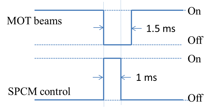
The cold atom cloud was formed around the waist of the nanofibre, ensuring that the atoms in the cloud interacted with the guided light via evanescent field coupling. The MOT beams, i.e. the cooling and repump beams, and the photon counter were switched on and off using the timing sequence shown in Fig. 7 in order to check absorption of the probe beam by the cold atoms. The trapping magnetic field and the probe beam were kept on at all times; however, the photons guided through the nanofibre were only counted during the 1 ms time when the MOT beams were off. A repetition rate of 5 Hz was used for the experiments to ensure that the atom cloud was fully loaded before proceeding with any measurements. This gave sufficient time for the cloud to return to its steady state by re-collecting any atoms lost in the 1 ms expansion during the detection phase. The photon counts were collected for 400 runs.
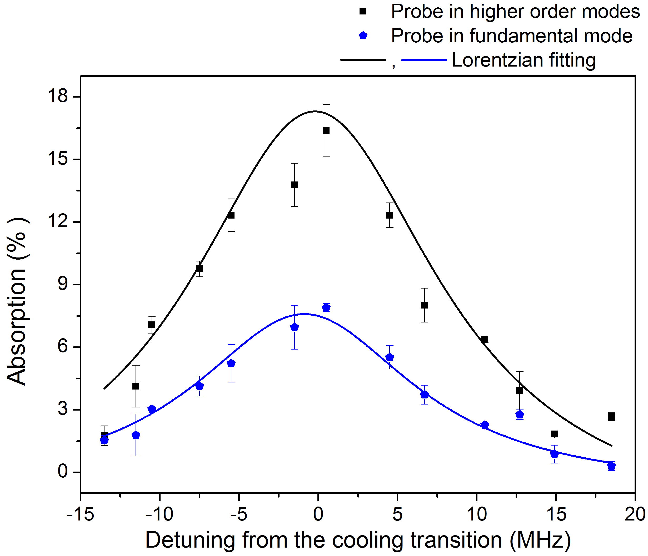
Next, the same collection sequence (Fig. 7) was repeated 400 times in the absence of an atom cloud, so as to determine the background signal. Using these two sets of data, the percentage absorption of the probe was calculated for a particular detuning with respect to the cooling transition of 87Rb. The same experiment was repeated using different probe beam detunings in order to obtain the absorption spectrum for the 87Rb cloud (Fig. 8). Finally, a similar experiment was performed for a fundamental mode probe in the nanofibre. We used the same power values at the output end of the nanofibre. Again, the percentage absorption signal for the atom cloud was obtained. From Fig. 8 one can see that the absorption appeared more pronounced when the LP11 mode group was at the nanofibre waist. For all cases the probe power was maintained at 4.3 pW at the output end in the cloud-off condition. Taking the transmission difference for the LP00 and LP01 modes into account, the probe power at the waist of the nanofibre for the higher order mode case was 1.7 times higher than for the fundamental mode. The absorption percentage for the higher order modes still appeared to be higher (by a factor of 2). This reflects the fact that more atoms surrounding the waist of the nanofibre interacted with the evanescent field for higher order modes, since they extend further from the fibre surface. The linewidths obtained by Lorentzian fitting to the spectra are similar in both the cases (19 5 MHz for the higher modes and 17 2 MHz for the fundamental mode).
4 Conclusion
In this work, we have demonstrated, for the first time, the propagation of higher order modes (the LP11 mode group) in an optical nanofibre integrated into a magneto-optical trap for neutral atoms. We have studied fluorescence from atoms coupled into the optical nanofibre guided modes. Our preliminary results appear to be in qualitative agreement with earlier theoretical predictions [23, 24], but further studies are necessary to fully understand the effects. In particular, state selection of the atoms should be performed [31]. We also observed absorption of the higher modes and, for a particular output power level, absorption appeared to be higher than that for the fundamental mode. The work presented in this paper enables numerous heretofore theoretical atom trapping schemes to finally be realised, such as that relying on modal interference of far detuned higher order modes [18]. Future work will focus on trapping atoms around the nanofibre using higher order mode combinations and will include consideration of alternative complex mode patterns [17].
5 Acknowledgments
This work was supported by the OIST Graduate University and Science Foundation Ireland under Grant No.08/ERA/I1761 through the NanoSci- E+ Transnational Programme, NOIs.
References and links
- [1] M. J. Morrissey, K. Deasy, Y. Wu, S. Chakrabarti and S. Nic Chormaic, “Tapered optical fibers as tools for probing magneto-optical trap characteristics, ” Rev. Sci. Instrum. 80, 053102 (2009).
- [2] E. Vetsch, D. Reitz, G. Sagué, R. Schmidt, S. T. Dawkins and A. Rauschenbeutel, “Optical interface created by laser-cooled atoms trapped in the evanescent field surrounding an optical nanofiber,” Phys. Rev. Lett. 104, 203603 (2010).
- [3] A. Goban, K. S. Choi, D. J. Alton, D. Ding, C. Lacroûte, M. Pototschnig, T. Thiele, N. P. Stern and H. J. Kimble, “Demonstration of a state insensitive, compensated nanofiber trap,” Phys. Rev. Lett. 109, 033603 (2012).
- [4] K. Hakuta and K. P. Nayak, “Manipulating single atoms and photons using optical nanofibers,” Adv. Nat. Sci.: Nanosci. Nanotechnol. 3, 015005 (2012).
- [5] P. Schneeweiss, F. Le Kien and A. Rauschenbeutel, “Nanofiber-based atom trap created by combining fictitious and real magnetic fields,” New J. Phys. 16 013014 (2014).
- [6] M. Daly, V. G. Truong, C. F. Phelan, K. Deasy and S. Nic Chormaic, “Nanostructured optical nanofibre for atom trapping,” New J. Phys. 16 053052 (2014).
- [7] G. Brambilla, G. S. Murugan, J. S. Wilkinson and D. J. Richardson, “Optical manipulation of microspheres along a subwavelength optical wire,” Opt. Lett. 32, 3041 (2007).
- [8] H. Lei, Y. Zhang, X. Li and B. Li, “Photophoretic assembly and migration of dielectric particles and Escherichia coli in liquids using a subwavelength diameter optical fiber,” Lab on a Chip 11, 2241 (2011).
- [9] M. Frawley, I. Gusachenko, V. G. Truong, M. Sergides and S. Nic Chormaic, “Selective particle binding and optical trapping in the evanescent field of an optical nanofiber,” Opt. Express 22, 16322 (2014).
- [10] L. Zhang, J. Lou and L. Tong, “Micro/nanofiber optical sensors,” Photonic Sensors 1, 31 (2011)
- [11] P. Wang, G. Brambilla, M. Ding, Y. Semenova, Q. Wu and G. Farrell, “A high sensitivity, evanescent field refractometric sensor based on tapered multimode fiber interference,” Opt. Lett. 36, 2233 (2011).
- [12] M. J. Morrissey, K. Deasy, M. Frawley, R. Kumar, E. Prel, L. Russell, V. G. Truong and S. Nic Chormaic, “Spectroscopy, Manipulation and Trapping of Neutral Atoms, Molecules, and Other Particles Using Optical Nanofibers: A Review,” Sensors 13, 10449 (2013).
- [13] K. P. Nayak and K. Hakuta, “Single atoms on an optical nanofibre,” New J. Phys. 10, 053003 (2008).
- [14] M. Das, A. Shirasaki, K. P. Nayak, M. Morinaga, F. Le Kien and K. Hakuta, “Measurement of fluorescence emission spectrum of few strongly driven atoms using an optical nanofiber,” Opt. Express 18, 17154 (2010).
- [15] L. Russell, R. Kumar, V. B. Tiwari and S. Nic Chormaic, “Measurements on release-recapture of cold Rb-85 atoms using an optical nanofibre”, Opt. Commun. 309, 313 (2013).
- [16] F. Le Kien, S. Dutta Gupta, V. I. Balykin and K. Hakuta, “Spontaneous emission of a cesium atom near a nanofiber: Efficient coupling of light to guided modes, ” Phys. Rev. A 72, 032509 (2005).
- [17] C. F. Phelan, T. Hennessy and T. Busch, “Shaping the evanescent field of optical nanofibers for cold atom trapping,” Opt. Express 21, 27093 (2013).
- [18] J. Fu, X. Yin, N. Li, and L. Tong, “Atom waveguide and 1D optical lattice using a two-color evanescent light field around an optical micro/nano-fiber,” Chin. Opt. Lett. 6, 112 (2008)
- [19] G. Sagué, A. Baade and A. Rauschenbeutel, “Blue-detuned evanescent field surface traps for neutral atoms based on mode interference in ultrathin optical fibres,” New J. Phys. 10, 113008 (2008).
- [20] M. C. Frawley, A. Petcu-Colan, V. G. Truong and S. Nic Chormaic, “Higher order mode propagation in an optical nanofiber,” Opt. Commun. 285, 4648 (2012).
- [21] S. Ravets, J. E. Hoffman, L. A. Orozco, S. L. Rolston, G. Beadie and F. K. Fatemi, “A low-loss photonic silica nanofiber for higher-order modes,” Opt. Express 21, 18325 (2013).
- [22] A. Petcu-Colan, M. Frawley and S. Nic Chormaic, “Tapered few-mode fibers: Mode evolution during fabrication and adiabaticity,” J. Nonlin. Opt. Phys. Mater. 20, 293 (2011).
- [23] A. V. Masalov and V. G. Minogin, “Pumping of higher-order modes of an optical nanofiber by laser excited atoms,” Laser Phys. Lett. 10, 075203 (2013).
- [24] A. V. Masalov and V. G. Minogin, “Spontaneous decay rates of the hyperfine structure atomic states into an optical nanofiber,” Journal of Experimental and Theoretical Physics 118, 714 (2014).
- [25] J. M. Ward, A. Maimaiti, Vu H Le and S. Nic Chormaic,“Optical Micro- and Nanofiber Pulling Rig,” arXiv:1402.6396 (2014).
- [26] A. Yariv, Optical Electronics, Saunders College Publishing, Philadelphia, fourth ed. (1991).
- [27] G. Volpe and D. Petrov, “Generation of cylindrical vector beams with few-mode fibers excited by Laguerre-Gaussian beams,” Opt. Commun. 237, 89 (2004).
- [28] N. Matsumoto, T. Ando, T. Inoue, Y. Ohtake, N. Fukuchi, and T. Hara, “Generation of high-quality higher-order Laguerre-Gaussian beams using liquid-crystal-on-silicon spatial light modulators,” JOSA A, 25, 1642 (2008).
- [29] S. Ravets, J. E. Hoffman, P. R. Kordell, J. D. Wong-Campos, S. L. Rolston, and L. A. Orozco, “Intermodal energy transfer in a tapered optical fiber: optimizing transmission,” JOSA A, 30, 2361 (2013).
- [30] E. R. I. Abraham and E. A. Cornell, “Teflon feedthrough for coupling optical fibers into ultrahigh vacuum systems,” Appl. Opt. 37, 1762 (1998).
- [31] F. Le Kien and A. Rauschenbeutel, “Anisotropy in scattering of light from an atom into the guided modes of a nanofiber,” Phys. Rev. A 90, 023805 (2014)