Delay-Robustness in Distributed Control of Timed Discrete-Event Systems Based on Supervisor Localization
()
Abstract
Recently we studied communication delay in distributed control of untimed discrete-event systems based on supervisor localization. We proposed a property called delay-robustness: the overall system behavior controlled by distributed controllers with communication delay is logically equivalent to its delay-free counterpart. In this paper we extend our previous work to timed discrete-event systems, in which communication delays are counted by a special clock event tick. First, we propose a timed channel model and define timed delay-robustness; for the latter, a polynomial verification procedure is presented. Next, if the delay-robust property does not hold, we introduce bounded delay-robustness, and present an algorithm to compute the maximal delay bound (measured by number of s) for transmitting a channeled event. Finally, we demonstrate delay-robustness on the example of an under-load tap-changing transformer.
Index Terms:
Timed Discrete-Event Systems, Distributed Supervisory Control, Supervisor Localization, Delay-robustness.I Introduction
For distributed control of discrete-event systems (DES), supervisor localization was recently proposed [1, 2, 3, 4] which decomposes a monolithic supervisor or a heterarchical array of modular supervisors into local controllers for individual agents. Collective local controlled behavior is guaranteed to be globally optimal and nonblocking, assuming that the shared events among local controllers are communicated instantaneously, i.e. with no delay. In practice, however, local controllers are linked by a physical communication network in which delays may be inevitable. Hence, for correct implementation of the local controllers obtained by localization, it is essential to model and appraise communication delays.
In [5] and its conference precursor [6], we studied communication delays among local controllers for untimed DES. In particular, we proposed a new concept called delay-robustness, meaning that the systemic behavior of local controllers interconnected by communication channels subject to unbounded delays is logically equivalent to its delay-free counterpart. Moreover, we designed an efficient procedure to verify for which channeled events the system is delay-robust. If for a channeled event the system fails to be delay-robust, there may still exist a finite bound for which the system can tolerate a delay in . In unitimed DES, however, there lacks a temporal measure for the delay bound (except for counting the number of occurrences of untimed events).
In this paper and its conference antecedent[7], we extend our study on delay-robustness to the timed DES (or TDES) framework proposed by Brandin and Wonham [8, 9]. In this framework, the special clock event tick provides a natural way of modeling communication delay as temporal behavior. We first propose a timed channel model for transmitting each channeled event, which effectively measures communication delay by the number of tick occurrences, with no a priori upper bound, so that the channel models unbounded delay. We then define timed delay-robustness with respect to the timed channel, thus extending its untimed counterpart [5, 6] in two respects: (1) the system’s temporal behavior is accounted for, and (2) timed controllability is required. A polynomial algorithm is presented to verify timed delay-robustness according to this new definition.
If the delay-robust property fails to hold, we introduce bounded delay-robustness and present a corresponding verification algorithm. In particular, the algorithm computes the maximal delay bound (in terms of number of s) for transmitting a channeled event, i.e. the largest delay that can be tolerated without violating the system specifications. These concepts and the corresponding algorithms are illustrated for the case of an under-load tap-changing transformer (ULTC).
Distributed/decentralized supervisory control with communication delay has been widely studied for untimed DES (e.g. [10, 11, 12, 13, 14, 15, 16, 17, 18]). In particular in [11, 15], the existence of distributed controllers in the unbounded delay case is proved to be undecidable; and in [11, 12, 13, 14, 16], distributed controllers are synthesized under the condition that communication delay is bounded. We also note that Sadid et al. [18] propose a way to verify robustness of a given synchronous protocol with respect to a fixed or a finitely-bounded delay, as measured by the number of untimed events occurring during the transmitting process. We refer to [5, 6] for a detailed review of these works and their differences from our approach. Communication delay in timed DES, on the other hand, has (to our knowledge) received little attention. The present work is based on our previous research on timed supervisor localization [3, 4].
The paper is organized as follows. Sect. II provides a review of the Brandin-Wonham TDES framework and recalls supervisor localization for TDES. In Sect. III we introduce a timed channel model, and present the concept and verification algorithm for timed delay-robustness.In Sect. IV we define bounded delay-robustness, and present an algorithm to compute the maximal delay bound. These concepts and the corresponding algorithms are demonstrated in Sect. V on the distributed control problem for an under-load tap-changing transformer (ULTC) with communications. Conclusions are presented in Sect. VI.
II Distributed Control by Supervisor Localization of TDES
II-A Preliminaries on TDES
The TDES model proposed by Brandin and Wonham [8] is and extension of the untimed DES generator model of the Ramadge-Wonham framework [9]. A TDES is given by
| (1) |
Here is the finite set of states; is the finite set of events including the special event , which represents “tick of the global clock”; is the (partial) state transition function (this is derived from the corresponding activity transition function; the reader is referred to the detailed transition rules given in [8, 9]); is the initial state; and is the set of marker states. The transition function is extended to in the usual way. The closed behavior of is the language and the marked behavior is . We say that is nonblocking if , where denotes prefix closure [9].
Let be the set of all finite strings, including the empty string . For , the natural projection is defined by
| (2) |
As usual, is extended to , where denotes powerset. Write for the inverse-image function of .
To adapt the TDES in (1) for supervisory control, we first designate a subset of events, denoted by , to be the prohibitible events which can be disabled by an external supervisor. Next, and specific to TDES, we bring in another category of events, called the forcible events, which can preempt event ; let denote the set of forcible events. Note that . Now it is convenient to define the controllable event set . The uncontrollable event set is .
We introduce the notion of (timed) controllability as follows. For a string , define to be the subset of events ‘eligible’ to occur (i.e. defined) at the state . Consider an arbitrary language and a string ; similarly define the eligible event subset . We say is controllable with respect to if, for all ,
| (7) |
Whether or not is controllable, we denote by the set of all controllable sublanguages of . Then is nonempty, closed under arbitrary set unions, and thus contains a unique supremal (largest) element denoted by [8, 9]. Now consider a specification language imposed on the timed behavior of ; may represent a logical and/or temporal requirement. Let the TDES
| (8) |
be the corresponding monolithic supervisor that is optimal (i.e., maximally permissive) and nonblocking in the following sense: ’s marked language is
and moreover its closed language is
II-B Supervisor Localization of TDES
In this subsection, we introduce the supervisor localization procedure, which was initially proposed in the untimed DES framework [1] and then adapted to the TDES framework [3, 4]. By this procedure, a set of local controllers and local preemptors is obtained and shown to be ‘control equivalent’ to the monolithic supervisor in (8). By allocating these constructed local controllers and preemptors to each component agent, we build a distributed supervisory control architecture.
Let TDES in (1) be the plant to be controlled and be a specification language. As in [9], synthesize the monolithic optimal and nonblocking supervisor . Supervisor ’s control action includes (i) disabling prohibitible events in and (ii) preempting via forcible events in . By the supervisor localization procedure, a set of local controllers and a set of local preemptors are constructed. These and are all TDES as in (1), and proved to be control equivalent to (with respect to ) in the following sense:
| (9) | ||||
| (10) |
Here and are the natural projections as in (2).
Now, using the constructed local controllers and local preemptors, we build a distributed supervisory control architecture (without communication delay) for a multi-agent TDES plant. Consider that the plant consists of component TDES (), each with event set . For simplicity assume , for all ; namely the agents are independent except for synchronization on the global event . As a result, the marked and closed behaviors of the composition of coincide with those of their synchronous product [9], and thus we use synchronous product instead of composition to combine TDES together, i.e. where denotes the synchronous product of TDES.111The closed and marked behaviors of are and , where denotes the synchronous product of languages [9].
A convenient allocation policy of local controllers/preemptors is the following. For a fixed agent , let be its forcible event set and prohibitible event set, respectively. Then allocate to the set of local controllers and the set of local preemptors . This allocation creates a distributed control architecture for the multi-agent plant , in which each agent is controlled by its own local controllers/preemptors, while interacting with other agents through communication of shared events. For agent , the set of communication events that need to be imported from other agents is
| (11) |
where and are the event sets of and of respectively.
However, this distributed control architecture is built under the assumption that the communication delay of communication events is negligible. While simplifying the design of distributed controllers, this assumption may be unrealistic in practice, where controllers are linked by a physical network subject to delay. In the rest of this paper, we investigate how the communication delay affects the synthesized local control strategies and the corresponding overall system behavior.
III Timed Delay-Robustness
Consider event communication between a pair of agents and (): specifically, sends an event to . Let be the event set of and as in (11) the set of communication events that imports from other agents. Then the set of events that sends to is
| (12) |
We thus have event .
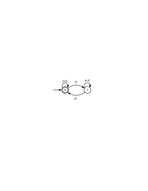
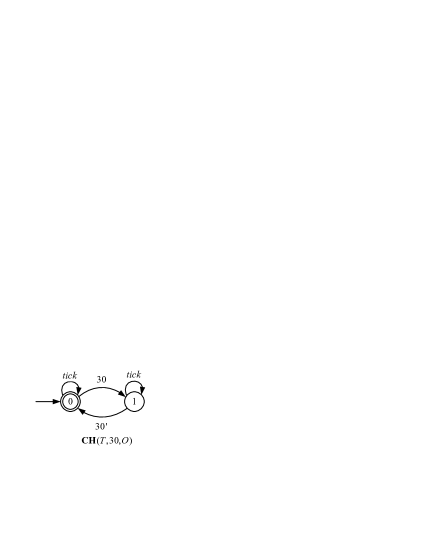
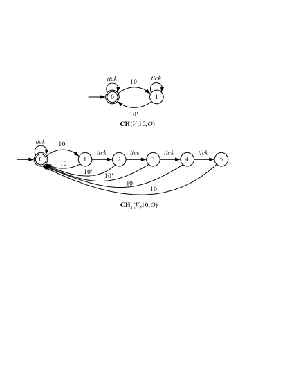
Now consider the timed channel model for transmission displayed in Fig. 1. is a 2-state TDES with event set . The transition from state 0 to 1 by means that has sent to channel, while the transition from state 1 back to 0 by means that has received from channel. We refer to as the signal event of , and assign its controllability status to be the same as (i.e. is controllable iff is controllable). The selfloop transition at state 1 therefore counts communication delay of transmission: the number of s that elapses between and . Measuring delay by events is a major improvement compared to the untimed channel model we used in [6] where no suitable measure exists to count delay. Later in Sect. IV, with the aid of this measure we will compute useful delay bounds for event communication.
It should be stressed that the number of occurrences between and is unspecified, inasmuch as the selfloop at state 1 may occur indefinitely. In this sense, models possibly unbounded communication delay. Note that is also selflooped at state 0; this is not used to count delay, but rather for the technical necessity of preventing the event from being blocked when synchronizing with other TDES. The initial state 0 is marked, signaling each completion of event transmission; state 1, on the other hand, is unmarked because the transmission is still ongoing.
The capacity of channel is 1, meaning that only when the latest occurrence of event is received by its recipient , will the channel accept a fresh instance of from . Hence, permits reoccurrence of (i.e. sends again) only when it is idle, namely at state 0. The capacity constraint of can be easily relaxed to allow multi-capacity channel models, as we shall see in Remark 1 below. We nevertheless adopt for its structural simplicity and suitability for clarifying the concept of delay-robustness presented next.
With the channel model , we may describe the channeled behavior of the system as follows. Suppose given , ; by localization (see Sect. II-B) acquires a set of local controllers and a set of local preemptors .222 For each state state of each controller (resp. preemptor ), and each communication event (resp. ), if is not defined at , we add a -selfloop, i.e. transition to (resp. ). Now, is defined at every state of (resp. ). With this modification, the new local controllers (resp. local preemptors ) are also control equivalent to SUP (because (resp. ) does not disable events from other components ) and the definition of at every state of (resp. ) is consistent with the assumption that (resp. ) may receive after indefinite communication delay. So the local controlled behavior of is
| (13) |
Observe that when sends to through , only the recipient ’s local behavior is affected because receives instead of due to delay. Hence each transition of must be replaced by its signal event ; we denote by the resulting new local behavior of . Now let
| (14) |
and then
| (15) |
So is the channeled behavior of the system with respect to . Note that both and are defined over .
Let and be natural projections (as in (2)). We define delay-robustness as follows.
Definition 1.
Consider that sends event to through channel . The monolithic supervisor in (8) is delay-robust with respect to if the following conditions hold:
(i) in (15) is correct and complete, i.e.
| (16) | |||
| (17) | |||
| (18) |
(ii) is controllable with respect to and , i.e.
| (19) |
In condition (i) above, ‘correctness’ of means that no -projection of anything can do is disallowed by , while ‘completeness’ means that anything can do is the -projection of something can do. In this sense, the channeled behavior is ‘equivalent’ to its delay-free counterpart . Specifically, conditions (16) and (17) state the equality of closed and marked behaviors between and the -projection of ; condition (18), which is required for ‘completeness’, states that if executes a string whose projection in can be extended by a string to a marked string of , then can further execute a string whose projection is and such that is marked in . Roughly, an observationally consistent inference about coreachability at the “operating” level of can be drawn from coreachability at the abstract (projected) level of .
Condition (ii) of Definition 1 imposes a basic requirement that channel , when combined with NSUP in (14) to form , should not entail uncontrollability with respect to . We impose condition (ii) no matter whether is controllable or uncontrollable. This is because we view the channel as a hard-wired passive adjunction to the original system, and therefore cannot exercise control on . In other words, the channel has to ‘accept’ any event that the rest of the system might execute, whether that event is controllable or uncontrollable. Thus if there is already an instance of in the channel (i.e. at state 1), then reoccurrence of will be (unintentionally) ‘blocked’, causing condition (ii) to fail. This issue persists, albeit in milder form, even if we use channel models of multiple (finite) capacities (see Remark 1 below).
We note that delay-robustness as defined above is an extension, from untimed DES to timed DES, of the concept proposed under the same name in [6] . In particular, the channel model used in the definition is capable of measuring transmission delay by counting occurrences; and condition (ii) in the definition requires controllability for timed DES.
Finally, we present a polynomial algorithm to verify the delay-robustness property. Notice that when (16) and (17) hold, then (18) is identical with the -observer property of [19, 20]. The latter may be verified in polynomial time (, the state size of ) by computing the supremal quasi-congruence of a nondeterministic automaton derived from and [19, 21].333We note en passant that [22] reports an algorithm with quadratic time complexity for verifying the observer property alone; that does not, however, yield structural information which (if the observer property is not satisfied) might be useful for remedial design. The following is the delay-robustness verification algorithm.
Algorithm 1
1. Check if is an -observer. If no, return false.
2. Check if and . If no, return false.
3. Check if is controllable with respect to and . If no, return false.
4. Return true.
If Step 1 above ( complexity) is successful, i.e. is indeed an -observer, then Step 2 of computing and is of polynomial complexity [21]. Then checking the two equalities in Step 2 is of complexity. Finally in Step 3, controllability may be checked using standard algorithm [8] in linear time . Therefore, Algorithm 1 terminates and is of polynomial complexity . The following result is straightforward.
Proposition 1.
Consider that sends event to through channel . The monolithic supervisor is delay-robust with respect to if and only if Algorithm 1 returns true.
Remark 1.
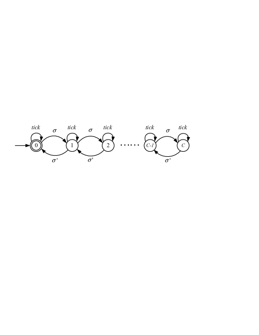
(Multi-capacity channel model) So far we have considered the 1-capacity channel model , and defined delay-robustness with respect to it. We now consider the more general -capacity channel model , a positive integer, displayed in Fig. 2. The sender may send at most instances of event to , each instance subject to indefinite delay. With channel , one may proceed just as before, by replacing by throughout, to define the corresponding delay-robustness property with respect to , and then revising Algorithm 1 correspondingly to verify delay-robustness.
It is worth noting that when reaches its maximal capacity, and sends yet another instance of , then is ‘blocked’ by , implying uncontrollability of the channeled behavior. Hence the uncontrollability problem always exists as long as the channel model is of finite capacity and delay is indefinite, although the controllability condition (cf. condition (ii) of Definition 1) is more easily satisfied for larger capacity channels (simply because more instances of may be sent to the channel).
IV Bounded Delay-Robustness and Maximal Delay Bound
Consider again the situation that agent sends an event to . If the monolithic supervisor is verified (by Algorithm 1) to be delay-robust, then we will use channel in Fig. 1 to transmit subject to unbounded delay, and the system’s behavior will not be affected. If, however, fails to be delay-robust, there are two possible implications: (1) must be transmitted without delay (as in the original setup of localization [1, 3, 4]); or (2) there exists a delay bound () of such that if each transmission of is completed within occurrences of , the system’s behavior will remain unaffected. This section aims to identify the latter case, which we call “bounded delay-robust”, and moreover to determine the bound .
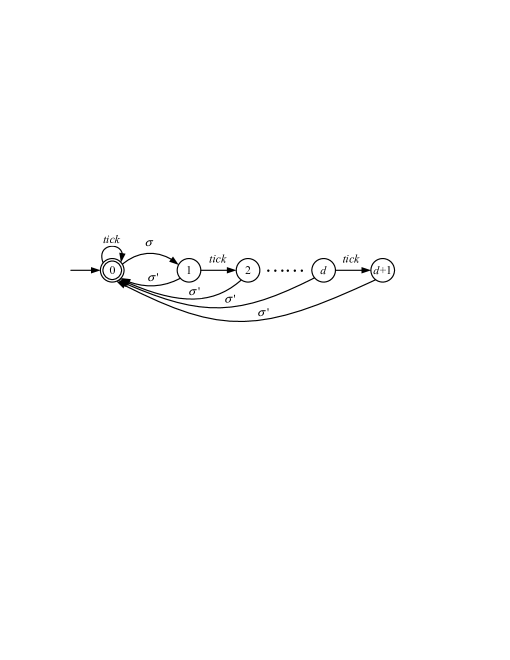
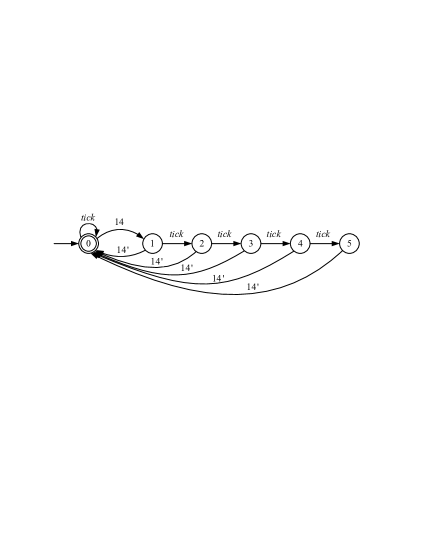
To that end, consider the channel model in Fig. 3, with parameter . is a -state TDES with event set . After an occurrence of (state 0 to 1), counts up to () occurrences of (state 1 through ) by which time the signal event must occur. That is, the occurrence of ( receives ) is bounded by s. Note that the selfloop at state 0 is again for the technical requirement to prevent the blocking of event when synchronizing with other TDES.
Now with , the channeled behavior of the system is
| (20) |
where is given in (14). The event set of is , and we recall the natural projections and .
Definition 2.
Consider that sends event to through channel , . The monolithic supervisor in (8) is bounded delay-robust with respect to (or d-bounded delay-robust) if the following conditions hold:
(i) in (20) is correct and complete, i.e.
| (21) | |||
| (22) | |||
| (23) |
(ii) is controllable with respect to and , i.e.
| (24) |
Bounded delay-robustness is defined in the same way as (unbounded) delay-robustness in Definition 1, but with respect to the new channel model with delay bound . As a result, -bounded delay-robustness may be verified by Algorithm 1 with corresponding modifications. For later reference, we state here the modified algorithm.
Algorithm 2
1. Check if is an -observer. If not, return false.
2. Check if and . If not, return false.
3. Check if is controllable with respect to and . If not, return false.
4. Return true.
Now if the monolithic supervisor fails to be (unbounded) delay-robust with respect to channel , we would like to verify if is bounded delay-robust with respect to for some . If so, compute the maximal delay bound, i.e. the largest delay (number of s) that can be tolerated without changing the system’s logical behavior. We need the following lemma.
Lemma 1.
Consider that sends event to through channel , . If is not -bounded delay-robust, then it is not -bounded delay-robust.
The result of Lemma 1 is intuitive: if cannot tolerate a transmission delay of , neither can it tolerate a delay . By induction, in fact, cannot tolerate any delay larger than . The proof of Lemma 1 is in Appendix A. This fact suggests the following algorithm for identifying bounded delay-robustness as well as computing the maximal delay bound.
Algorithm 3
1. Set .
2. Check by Algorithm 2 if is -bounded delay-robust relative to channel . If not, let and go to Step 3. Otherwise advance to and repeat Step 2.
3. Output .
Lemma 2.
If is not delay-robust with respect to , then Algorithm 3 terminates in at most steps, i.e. , where m is the state size of in (15).
The proof of Lemma 2 is given in Appendix B. In Algorithm 3, we work upwards starting from the minimal delay . If is not -bounded delay-robust with respect to , then by Lemma 1 is not -bounded delay-robust for any . Therefore is not bounded delay-robust and must be transmitted without delay. Note that in this case Algorithm 3 outputs .
If is -bounded delay-robust, we next check if it is -bounded delay-robust with respect to . If fails to be -bounded delay-robust, then again by Lemma 1 fails to be -bounded delay-robust for any . Hence is bounded delay-robust, with the maximal delay bound .
If is shown to be -bounded delay-robust, the iterative process continues until fails to be -bounded delay-robust for some ; this happens in finitely many steps according to Lemma 2. Then is bounded delay-robust, with the maximal delay bound . The following result is immediate.
Proposition 2.
Consider that sends event to through channel , . The monolithic supervisor is bounded delay-robust with respect to if and only if the output of Algorithm 3 satisfies . Moreover, if is bounded delay-robust, then is the maximal delay bound for transmission.
To summarize, when an event is sent from to , we determine unbounded or bounded delay-robustness and choose the corresponding channel as follows.
Algorithm 4
1. Check by Algorithm 1 if is (unbounded) delay-robust. If so, terminate, set the maximal delay bound , and use channel in Fig. 1.
2. Check by Algorithm 3 if is bounded delay-robust. If so (i.e. ), terminate and use channel in Fig. 3 with .
3. In this case . Terminate and use no channel: must be transmitted without delay.
Remark 2.
(Multiple channeled events) So far we have considered a single event communication: agent sends event to . Using this as a basis, we present an approach to the general case of multiple channeled events, as is common in distributed control. We will consider that each fixed triple (sender, channeled event, receiver) is assigned with its own communication channel, and the assigned channels operate concurrently. Our goal is to obtain these channels, ensuring unbounded or bounded delay-robustness, one for each triple (sender, channeled event, receiver).
First fix , and recall from (12) that is the set of events that sends to . Write , , and treat the channeled events , , … sequentially, in order of indexing.
Algorithm 5
1. Set .
2. For event apply Algorithm 4 to obtain the maximal delay bound .
2.1. If , namely unbounded delay-robustness, choose channel , and let .
2.2. If is finite, namely bounded delay-robustness, choose channel , and let .
2.3 If , then no channel is chosen and must be transmitted without delay.
If , advance to and repeat Step 2.
3. Output a set of channels used for sending events from to .
Note that at Step 2 of Algorithm 5, if a channel is chosen for event , then must be reset to be the synchronous product of and the channel, so that in choosing a channel for the next event the previously chosen channel is considered together. This ensures that when the derived channels operate concurrently, the system’s behavior is not affected. It is worth noting that a different ordering of the set may result in a different set of channels; if no priority of the transmission delay is imposed on the communication events, we may choose an ordering randomly.
Finally, since the set of all communication events is , we simply apply Algorithm 5 for each (ordered) pair to derive all communication channels. Again, a different ordering of the set generally results in a different set of channels, because the channels chosen for a pair will be used to decide channels for all subsequent . For convenience we will simply order the pairs sequentially first on then on .
V Case Study: Under-Load Tap-Changing Transformer
In this section we demonstrate timed delay-robustness and associated verification algorithms on an under-load tap-changing transformer system.
V-A Model Description and Supervisor Localization
Transformers with tap-changing facilities constitute an important means of controlling voltage at all levels throughout electrical power systems. We consider an under-load tap-changing transformer (ULTC) as displayed in Fig. 4, which consists of two components: Voltmeter and Tap-Changer[23].

This ULTC is operated in two modes: Automatic and Manual. In the automatic mode, the tap-changer works according to the following logic. (1) If the voltage deviation is greater than some threshold value, then a timer will start; when the timer times out, a ‘tap increase (or decrease) event’ will occur and the timer will reset; a tap increase or decrease should only occur if the voltage change continues to exceed threshold after the time out- this is to avoid tap changes in response to merely occasional random fluctuations of brief duration. (2) If the voltage returns to the dead-band, because of a tap change or some other reason, then no tap change will occur. (3) If the voltage exceeds the maximally allowed value , then lowering of the tap command without delay occurs instantaneously. In the manual mode, the system is waiting for ‘Tap-up’, ‘Tap-down’, or ‘Automatic’ commands. An operator can change the operation mode from one to the other, and thus the operator is adjoined into the plant components to be controlled.
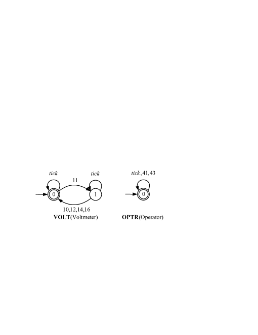
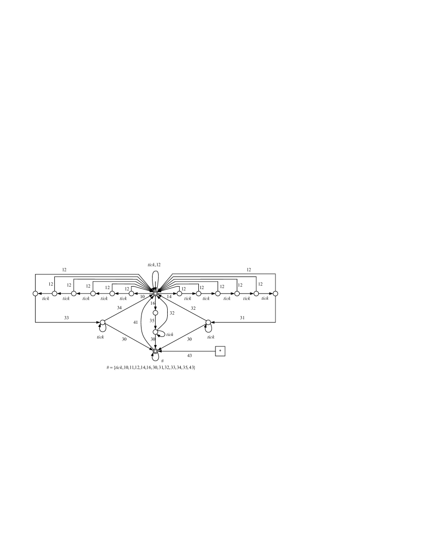
Each plant component is modeled as a TDES displayed in Fig. 5, and associated events are listed in Table I. So, the plant to be controlled is the synchronized behavior of Voltmeter (), Tap-changer () and Operator (), i.e.
| (25) |
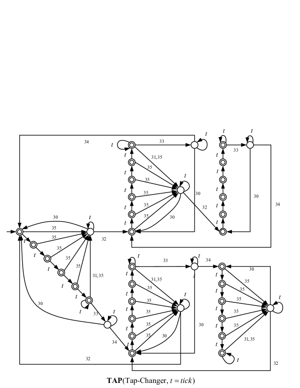
| Event | Physical interpretation | Time bounds | (hib/for) |
|---|---|---|---|
| (lower, upper) | |||
| 11 | Initialize voltmeter | (0, ) | hib |
| 10 | Report and | (0, ) | |
| 12 | Report , i.e. voltage recovered | (0, ) | |
| 14 | Report and | (0, ) | |
| 16 | Report voltage exceeds | (0, ) | |
| 30 | Tap-up/Down failed | (0, ) | |
| 31 | Tap-down command with 5 delay | (5, ) | hib & for |
| 32 | Tap-down successful | (0, ) | |
| 33 | Tap-up command | (0, ) | hib & for |
| 34 | Tap-up successful | (0, ) | |
| 35 | Tap-down command without delay | (0, ) | hib & for |
| 41 | Enter Automatic mode | (0, ) | hib |
| 43 | Enter Manual mode | (0, ) | hib |
We consider a voltage control problem of the ULTC: when the voltage is not ‘normal’, design controllers to recover the voltage through controlling tap ratio after a time delay to recover the voltage. Fig. 6 displays the TDES model for the control specification in Automatic/Manual mode.
Note that since the tap increase (decrease) and lowering tap commands would preempt the occurrence of , the corresponding events 31, 33 and 35 are designated as forcible events. In the following, we synthesize the monolithic supervisor by the standard TDES supervisory control theory [8, 9] and the local controllers by TDES supervisor localization [3, 4].
First, synthesize the monolithic supervisor TDES in the usual sense that its marked behavior
| (26) |
and its closed behavior . has 231 states and 543 transitions, and embodies disabling actions for all the prohibitible events and preempting actions relative to for all the forcible events.
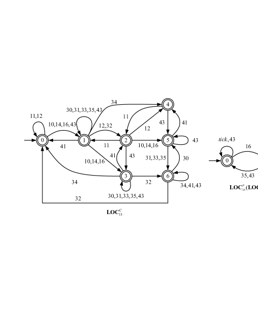
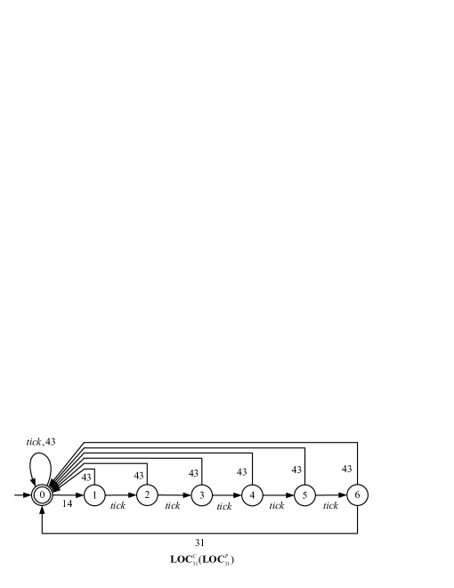
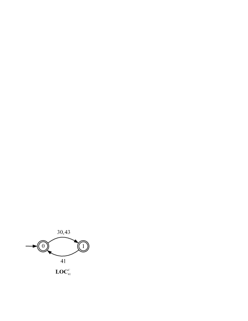
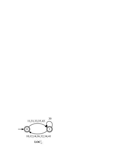
Next, by supervisor localization, we obtain a set of local controllers , , , and for controllable events 11, 31, 33, 35, 41 and 43 respectively, and a set of local preemptors , and for forcible events 31, 33 and 35 respectively; their transition diagrams are shown in Fig. 7.
Finally, using these constructed local controllers/preemptors, we build a distributed control architecture without communication delays for ULTC as displayed in Fig. 8. The local controlled behaviors of the plant components are
Let represent the set of events that component sends to component ; the sets of communication events are
| (27) | ||||
It is guaranteed by supervisor localization of TDES [3, 4] that the ULTC under the control of these local controllers and preemptors without communication delay, has closed and marked behavior identical to in (26).

V-B Delay-Robustness Verification
Now we investigate the timed delay-robustness property for ULTC. For illustration, we consider the following three cases.
(1) Event 30 in
Applying Algorithm 4, at Step 1 we verify by Algorithm 1 that is delay-robust with respect to the communication channel transmitting event 30, as displayed in Fig. 9.
To illustrate that the overall system behavior will not be affected by indefinite communication delay of event 30, consider the case that the voltmeter reported an increase in voltage (in as displayed in Fig. 5, events 11 and 10 have occurred), and the tap has received a tap-up command, but the tap-up operation failed (in as displayed in Fig. 5, events , , , , , 33 and 30 have occurred in sequence). By inspection of the transition diagrams, the plant components , and in Fig. 5 are at states 0, 0, and 0 respectively, and thus the events that are eligible to occur are 11, 35, 41, 43, and . However, according to the transition diagrams of the local controllers and preemptors displayed in Fig. 7: (1) is at state 1 and disables event 11; (2) is at state 0 and disables event 35; (3) will disable or enable event 41 depending on the communication delay of event 30; (4) is at state 1 and disables event 43; (5) will not be preempted, since no forcible event is enabled. If 30 is transmitted instantly, event 41 is enabled by and the system will enter the automatic mode. If the transmission of 30 is delayed, only event is enabled, and other events will not be enabled until the system enters the automatic mode. However, according to the transition diagram of displayed in Fig. 7, only after has received the occurrence of event 30, will it enable event 41, and bring the system into the automatic mode. Hence, the overall system behavior will not be affected even if the communication of event 30 is delayed.
(2) Event 10 in
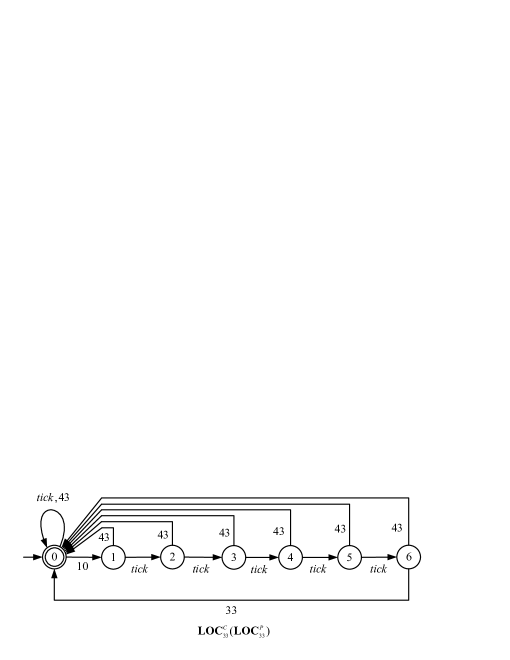
Applying Algorithm 4, at Step 1 we verify by Algorithm 1 that fails to be delay-robust with respect to the channel , as displayed in Fig. 10; then at Step 2, we check by Algorithm 3 that the maximal delay bound for event 10 is 4, i.e. is bounded delay-robust with respect to the channel , as displayed in Fig. 10.
To illustrate that is not delay-robust with respect to , but is bounded delay-robust with respect to , we consider the case that an increase in the voltage is reported (i.e. events 11 and 10 in have occurred sequentially). By inspection of the transition diagrams of the plant components shown in Fig. 5, the events that are eligible to occur are 11, 35, 41, 43, and . According to the transition diagrams of the local controllers and preemptors displayed in Fig. 7, if knows the voltage increase before the fifth tick occurs, the tap-changer will generate a tap-up command and the operator can switch the system into manual mode; otherwise, the tap-changer will also generate a tap-up command, but the system cannot enter the manual mode. In terms of language, event 43 will be enabled after the event sequence (where event 310 is the signal event of 10), but is disabled after . When observing and from the projection that erases the signal event 310, they cannot be distinguished. However, the system can enter the manual mode after the sequence , but not after . In other words, the system can not ‘complete’ the behavior of entering manual mode after , but this behavior can be finished in its delay-free counterpart . So, the observer property (23) required by bounded delay-robustness is violated when the delay bound exceeds 4 s, and we conclude that the maximal delay bound for event 10 is 4.
Similarly, one can verify by Algorithm 4 that is bounded delay-robust with respect to , as displayed in Fig. 11, and any other events except 10, 14 and 30 must be transmitted without delay.
(3) All communication events in (V-A)
Applying Algorithm 5 to each of the sets of communication events in (V-A) in sequence, we obtain that , , and for the remaining events, . In the following, we verify that if all the communication events are communicated within their corresponding delay bounds, the overall system behavior will still not be affected.
First, use , and to transmit events 30, 10 and 14 respectively. Second, connected by these channels, the overall system behavior is
over the augmented alphabet , where is obtained by replacing 10, 14, and 30 by , and respectively. Third, one can verify that: (1) is correct and complete, and (2) , and will not cause uncontrollability with respect to the uncontrollable communication events. Finally, we conclude that the overall system behavior is still optimal and nonblocking.
VI Conclusions
In this paper we have studied communication delays among local controllers obtained by supervisor localization in TDES. First, we have identified properties of ‘timed delay-robustness’ which guarantee that the specification of our delay-free distributed control continues to be enforced in the presence of (possibly unbounded) delay, and presented a polynomial verification algorithm to determine delay-robustness. Second, for those events that fail to be delay-robust, we have proposed an algorithm to determine their maximal delay bound such that the system is -bounded delay-robust. Finally, a ULTC example has exemplified these results, showing how to verify the delay-robustness, determine the maximal delay bound for bounded delay-robustness, and in addition, obtain a set of maximal delay bounds, one for each communication event, under the condition that the overall system behavior is still optimal and nonblocking.
With the definitions and tests reported here as basic tools, our future work will include the investigation of alternative more complex channel models and, of especial interest, global interconnection properties of a distributed system of TDES which may render delay-robustness more or less likely to be achieved.
Appendix A Proof of Lemma 1
Lemma 3.
For any delay bound , there hold
| (28) | ||||
| (29) |
Proof: Note that for different delay bounds , the alphabets of and are and , respectively. Here we only prove that ; (29) can be proved in the same way by replacing by throughout.
Let ; we must show that there exists a string such that . We first consider that only one instance of appeared in , and write where are free of . By (20) and observing that is obtained by replacing each instance of by , we obtain that . Furthermore, . So, . This result can be easily extended to the general case that has multiple instances of , because is transmitted by the channel model and the reoccurrence of is permitted only when transmission of the previous is completed. Namely, if , there exists a string such that and . Hence, we declare that .
Lemma 4.
Let where are strings free of and , i.e. . Then .
Proof of Lemma 4: Recall that is with transitions labeled relabeled . By definition of synchronous product, , and can be re-ordered without affecting the membership of in , namely the strings formed from by the successive replacement
will belong to as well. In other words, if the transmission of is completed in a shorter time (the number of ticks in will be smaller than that in ), the behavior is still legal.
Proof of Lemma 1: We prove Lemma 1 by contraposition, i.e. if is -bounded delay-robust, then it is also -bounded delay-robust. To that end, we must verify (21)-(24).
(1) For (21), we prove that and in sequence. is obtained from Lemma 3 immediately. By inspection of the transition diagram of in Fig. 3, we get that . So according to (20),
| (30) |
Since is bounded delay-robust, . Hence, .
(3) For (23), assume that and ; we must show that there exists a string such that and .
By (30), we have . Since is bounded delay-robust, there exists a string such that and . Here we consider the case that only one instance of exists in ; the general cases can be confirmed similarly (since the transmission of multiple instances of does not result in mutual interference). In the following, we prove (23) from these three cases: (i) , (2) , and (iii) , where are free of and .
(i) . By (20), we have . Similarly, since , . Further, , which means that after string , has reset the channel . Thus . On the other hand, because is free of , . Hence, . Define ; then and , as required by (23).
(ii) . By Lemma 4,, it results from that . The rest is similar to case (1); in this case, .
(iii) . By Lemma 4, we have . Also, the rest is similar to case (1); in this case, .
(4) Let and ; we show that by contraposition. Assume that . Write where . We claim that ; otherwise, is defined at state and . By inspection of the transition diagrams of and , it results from , that . Hence, , in contradiction to the fact that is bounded delay-robust.
Appendix B Proof of Lemma 2
Since is not delay-robust wrt. , by Definition 1, one of the conditions (16)-(19) is violated. In the following, we prove that in each case, , where is the states number of in (15).
(1) Condition (16) is violated. Since that always holds (similar to Lemma 3), we have . So, there exists at least one string such that , but . We claim that can be written as where ; otherwise, does not contain any , and it follows from the construction of that , a contradiction. As illustrated in Fig. 12, we prove in the following that there exist strings and such that (where represents the number of events appearing in string ), , but , from which we can conclude: to prevent the occurrence of string , the maximal communication delay of must be less than , i.e. .
By and , we have . To identify such strings, we build an TDES such that
and
i.e., , and .
First, we build such that and by the following two steps: (i) construct by applying the subset construction algorithm on with natural projection , and (ii) obtain by marking all states of . Second, we build such that and by first adjoining a (non-marker) dump state to the state set of and transitions for each state of if is not defined at (i.e. ), and secondly setting to be the only marker state. Third, let ; then , . The state size , since has at most states (due to the subset construction algorithm), and has states .
Finally, by , there exists a state such that ; by , there exists a marker state such that . So, there exists at least a simple string444The concept ‘simple string’ is derived from the ‘simple path’ in graphic theory, where a path is called simple if no vertex is traversed more than once[24]. Here string is called simple if no state is traversed more than once. joining and such that , and thus . It follows that . So, there exist strings such that , , , and , namely the occurrence of after violates condition (16). Since is simple, we have . By , we have . Furthermore, since represents the system behavior with communication delay, we always have . So , as required.
(2) Condition (17) is violated. can be confirmed similar to case (1).
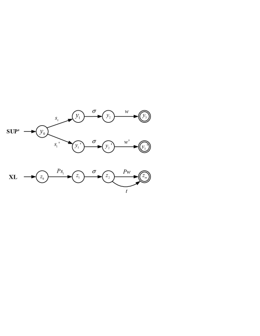
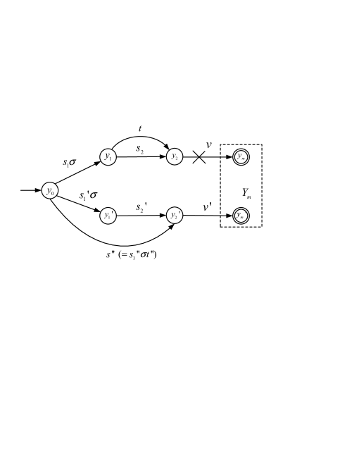
(3) Condition (18) is violated. Since delay-robustness of is violated by the communication delay of , there must exist strings , , and , such that and , but no string satisfies that and . As illustrated in Fig.13, we prove in the following that the condition (18) is also violated by the string pair and where and , from which we conclude: to prevent the occurrences of the strings and , the communication delay of must be less than , i.e. .
To that end, we need the concept ‘normal automaton’[25]. For , we say that is -normal if
| (31) |
where . In case is not -normal, replace by where is a deterministic generator over obtained by the subset construction. is always -normal, and and . The state size of the new is at most .
By , there must exist strings , , and such that , , , and , as displayed in Fig. 13. Let , , , and . Joining and , there must exist a simple string such that . So, . By -normality of , there must exist a string such that , , and . So string can be written as where and , and the condition (18) is also violated by the string pair and . Because is simple, , where is the state size of -normal form of . So, when is not -normal, . In addition, since , , as required.
(4) Condition (19) is violated. In this case, assume that is blocked at state of , and the last occurrence of occurs at state of . From to , there must exist a simple string . We claim that the maximal communication delay of must be less that ; otherwise, the system will arrive at state by string . Hence .
Finally, by comparing in the above four cases, we conclude that if is not delay-robust with respect to , .
References
- [1] K. Cai and W. M. Wonham, “Supervisor localization: a top-down approach to distributed control of discrete-event systems,” IEEE Trans. on Automatic Control, vol. 55, no. 3, pp. 605–618, March 2010.
- [2] K. Cai and W. Wonham, “Supervisor localization for large discrete-event systems: case study production cell,” International J. of Advanced Manufacturing Technology, vol. 50, no. 9-12, pp. 1189–1202, October 2010.
- [3] R. Zhang, K. Cai, Y. Gan, Z. Wang, and W. Wonham, “Supervision localization of timed discrete-event systems,” Automatica, vol. 49, no. 9, pp. 2786–2794, 2013.
- [4] K. Cai, R. Zhang, and W. Wonham, “Supervision localization of timed discrete-event systems,” in Proc. 2013 American Control Conference, Washington DC, 2013, pp. 5666–5671.
- [5] R. Zhang, K. Cai, Y. Gan, Z. Wang, and W. Wonham, “Distributed supervisory control of discrete-event systems with communication delay,” 2014, technical report, online at http://arxiv.org/abs/1207.5072.
- [6] ——, “Checking delay-robustness of distributed supervisors of discrete-event systems,” in Proc. Int. Conf. on Information Science and Control Engineering, Shenzhen, China, 2012, pp. 350–355.
- [7] R. Zhang, K. Cai, and W. Wonham, “Delay-robustness in distributed control of timed discrete-event systems based on supervisor localization,” accepted by the 53rd IEEE Conference on Decision and Control, 2014.
- [8] B. Brandin and W. Wonham, “Supervisory control of timed discrete-event systems,” IEEE Trans. on Automatic Control, vol. 39, no. 2, pp. 329–342, February 1994.
- [9] W. Wonham, Supervisory Control of Discrete-Event Systems. Systems Control Group, ECE Dept, Univ. Toronto, Toronto, ON, Canada, July 2014, available at http://www.control.utoronto.ca/DES.
- [10] G. Barrett and S. Lafortune, “Decentralized supervisory control with communicating controllers,” IEEE Trans. on Automatic Control, vol. 45, no. 9, pp. 1620–1638, September 2000.
- [11] S. Tripakis, “Decentralized control of discrete-event systems with bounded or unbounded delay communication,” IEEE Trans. on Automatic Control, vol. 49, no. 9, pp. 1489–1501, September 2004.
- [12] K. Schmidt, E. Schmidt, and J. Zaddach, “A shared-medium communication architecture for distributed discrete event systems,” in Proc. Mediterranean Conf. on Control and Automation, Athens, Greece, 2007, pp. 1–6.
- [13] S. Xu and R. Kumar, “Asynchronous implementation of synchronous discrete event control,” in Proc. 9th Int. Workshop on Discrete Event Systems (WODES’08), 2008, pp. 181–186.
- [14] K. Hiraishi, “On solvability of a decentralized supervisory control problem with communication,” IEEE Trans. on Automatic Control, vol. 54, no. 3, pp. 468–480, March 2009.
- [15] G. Kalyon, T. L. Gall, H. Marchand, and T. Massart, “Synthesis of communicating controllers for distributed systems,” in Proc. 2011 50th IEEE Conference on Decision and Control and European Control Conference (CDC-ECC), Orlando, FL, USA, December 2011.
- [16] F. Lin, “Control of networked discrete event systems: dealing with communication delays and losses,” SIAM J. Control and Optimization, vol. 52, no. 2, pp. 1276–1298, 2014.
- [17] P. Darondeau and L. Ricker, “Distributed control of discrete-event systems: A first step,” Transactions on Petri Nets and Other Models of Concurrency, vol. 6, pp. 24–45, 2012.
- [18] W. Sadid, L. Ricker, and S. Hashtrudi-Zad, “Robustness of synchronous communication protocols with delay for decentralized discrete-event control,” Discrete Event Dynamic Systems, 2014, published online, available at http://link.springer.com.
- [19] K. Wong and W. Wonham, “On the computation of observers in discrete-event systems,” Discrete Event Dynamic Systems, vol. 14, no. 1, pp. 55–107, January 2004.
- [20] L. Feng and W. M. Wonham, “Supervisory control architecture for discrete-event systems,” IEEE Trans. Autom. Control, vol. 53, no. 6, pp. 1449–1461, 2008.
- [21] L. Feng and W. Wonham, “On the computation of natural observers in discrete-event systems,” Discrete Event Dynamic Systems, vol. 20, no. 1, pp. 63–102, March 2010.
- [22] H. Bravo, A. da Cunha, P. Pena, R. Malik, and J. Cury, “Generalised verification of observer property in discrete event systems,” in Proc. 11th International Workshop on Discrete Event Systems(WODES2012), Guadalajara, Mexico, October 2012, pp. 337–342.
- [23] A. Afzalian, A. Saadatpoor, and W. Wonham, “Systematic supervisory control solutions for under-load tap-changing transformers,” Control Engineering Practice, vol. 16, pp. 1035–1054, 2008.
- [24] G. Danielson, “On finding simple paths and circuits in a graph,” IEEE Trans. on Circuit Theory, vol. 15, no. 3, pp. 294–295, 1968.
- [25] S. Takai and T. Ushio, “Effective computation of Lm(g)-closed, controllable, and observable sublanguage arising in supervisory control,” Systems & Control Letters, vol. 49, no. 3, pp. 191–200, 2003.