Design and test of an extremely high resolution Timing Counter for the MEG II experiment: preliminary results
Abstract
The design and tests of Timing Counter elements for the upgrade of the MEG experiment, MEG II, are presented. The detector is based on several small plates of scintillator with a Silicon PhotoMultipliers dual-side readout. The optimisation of the single counter elements (SiPMs, scintillators, geometry) is described. Moreover, the results obtained with a first prototype tested at the Beam Test Facility (BTF) of the INFN Laboratori Nazionali di Frascati (LNF) are presented.
keywords:
Photon detectors for UV, visible and IR photons (solid-state) (PIN diodes, APDs, Si-PMTs, CCDs, EBCCDs etc), Scintillators, scintillation and light emission processes (solid, gas and liquid scintillators), Timing detectors1 Introduction: the MEG experiment
The MEG experiment has been running since 2008 at the Paul Scherrer Institut (Villigen, CH), looking for the decay. The MEG collaboration recently published the results based on the analysis of data collected in the years 2009-2011: BR() @90 C.L. [1]. While the analysis of the 2012-2013 data is still ongoing, an upgrade program of the MEG experiment (MEG II) has unfolded since 2012 [2], aiming to improve the experiment sensitivity by an order of magnitude, down to . In order to reach such a sensitivity, most of the current detectors have to be re-designed or modified. In this paper, the development of an extremely high resolution detector for the measurement of the positron timing is described in detail.
2 The Timing Counter upgrade
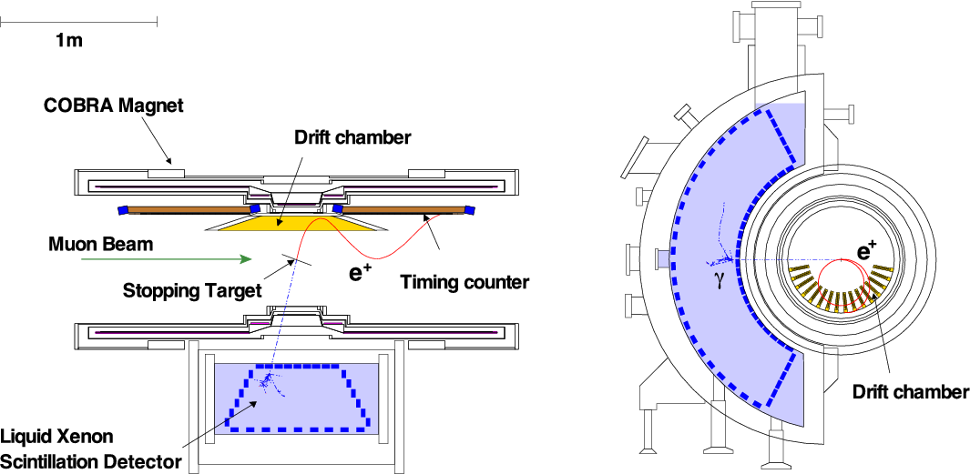
The MEG detector [3] is designed to measure with the highest possible resolution the kinematic variables that define the signature of the decay . Photons are detected by a Liquid Xenon detector placed outside the magnetic spectrometer where positrons are reconstructed (see figure 1). The spectrometer is made of a superconductive magnet, a set of Drift CHambers (DCH) and the Timing Counter (TC). The DCH system, together with the specially designed field provided by the COBRA magnet, measures positron energy and emission angle, while the purpose of the TC is to measure the positron time of impact.
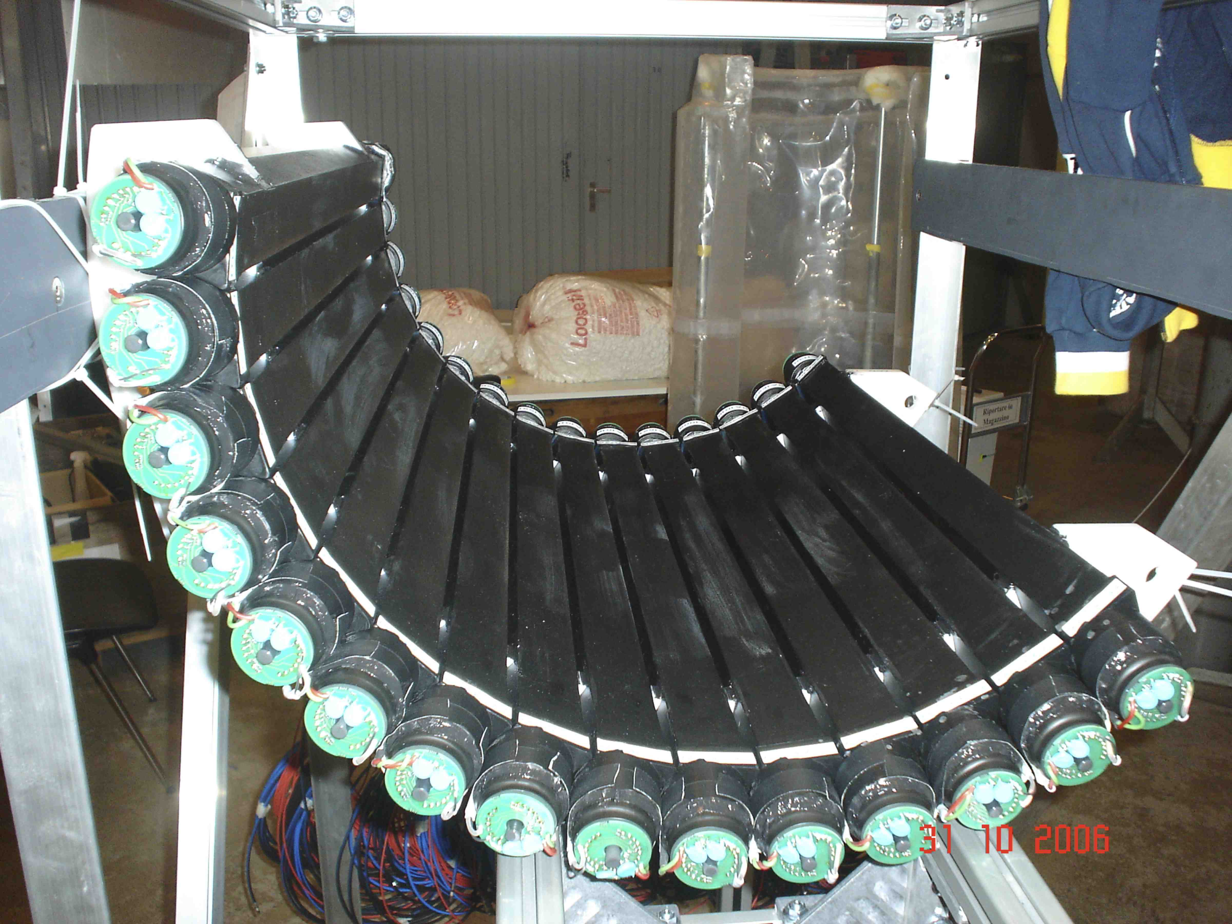
The current Timing Counter [4] is made of two identical arrays (placed inside the magnet
up- and down-stream the target position) of 15 scintillating bars (Bicron BC404), with size arranged in a barrel-like shape (see figure 2).
Each bar is read-out on both sides by a fine mesh PhotoMultiplier Tube (PMT, Hamamatsu R5924).
Signals from PMTs are processed to be fed into the trigger and DAQ system.
The Timing Counter has been running since 2008, showing good and stable time resolution of ps [5].
Some issues suggest that the design of the detector has to be changed to increase the resolution:
-
•
the PMT operation in high magnetic field and helium environment deteriorates the PMT transit time spread and gain, also using fine mesh PMTs;
-
•
large size scintillator bars generate uncertainties on impact point reconstruction and spread of the trajectories of the optical photons inside the scintillator itself;
-
•
the large amount of material crossed by the positron in the TC bar prevents the use of hits beyond the first one.
These problems originate from the usage of PMTs and large size scintillator bars. Thus, the natural choice is to increase the detector granularity and to upgrade the read-out system, exploiting the recent development of fast high gain solid state detector like Silicon PhotoMultipliers (SiPMs). A detector consisting of many scintillator plates (from now on: pixel) with SiPM read-out allows to overcome the limitations of the current TC (see figure 3 as possible layout):
-
•
magnetic field has no influence on SiPM operation;
-
•
higher granularity results in smaller uncertainties from impact position measurement;
-
•
thanks to the smaller amount of material along the positron trajectory, it is possible to take advantage of the information coming from all the pixels crossed by the particle.

The last point is quite remarkable, because the time resolution is expected to improve as , where is the number of pixels crossed by the positron.
Moreover, the small size of the single element results in a more flexible configuration of the detector, allowing the possibility to tailor the position and the density of the pixels along the detector. Also, very short rise time scintillator (like Bicron BC422, see section 3.2) can be used even in presence of a short attenuation length.
Single counter good performances have already been proved [6, 7]. In the following, the research and development work on several prototypes in order to choose the best material and device is presented.
3 Single counter optimisation
The optimisation of the single counter configuration started from a systematic study among the SiPMs and the scintillators available to compare the properties relevant for our application.
3.1 SiPM comparison
Silicon Photomultipliers are good candidate for the new TC, thanks to their characteristics: good time resolution, quite high gain, compactness. We tested different models from Hamamatsu Photonics, Advansid, Ketek and SensL. All these devices share some features: they have a size mm3, in order to be easily coupled to few mm thick scintillator pixels, and a good sensitivity in the near ultraviolet range, in order to match common plastic scintillators emission spectra. The SiPM models under test are summarised in table 1.
| Manufacturer | Model | Type | Note |
|---|---|---|---|
| S10362-33-050C | Conventional (Old) MPPC | Ceramic package | |
| S10931-050P | surface mount | ||
| Hamamatus Photonics | S12572-050C(X) | New (standard type) MPPC | Metal quench resistor |
| S12572-020C(X) | 25 pitch | ||
| S12652-050C(X) | Trench-type MPPC | Metal quench resistor | |
| 3X3MM50UMLCT-B | Improved fill factor | ||
| Advansid | NUV type | ||
| Ketek | PM3350 prototype-A | Trench Type | |
| SensL | MicroFB-30050-SMT | B-Type | Fast output |
For each model, the noise level (dark count rate and cross-talk) together with the Photon Detection Efficiency (PDE) has been evaluated. Moreover, also the breakdown dependence on temperature has been evaluated. Finally, the timing resolution has been measured on a prototype pixel with fixed sizes.
Setup
SiPMs are put in a thermal chamber, which allows to keep the device at fixed temperature (23∘C in the following measurements). Signals are transmitted on a coaxial cable to a voltage amplifier (developed at PSI, based on MAR-6SM amplifier [6]), then they are sampled at 5 Gs/s by a waveform digitiser (DRS4 evaluation board [8, 9] also developed at PSI).
Dark noise and cross-talk
The noise level of the device is evaluated by looking at the waveforms acquired by a random trigger. The dark count rate is calculated from the probability of observing zero photo-electron P(N= 0) in a fixed time window. The result is shown in figure 4 as a function of the applied over-voltage.
The cross-talk probability is calculated from the P(N)/P(N) ratio including a correction for the accidental coincidence of dark pulses. The result is shown in figure 4. The cross-talk probability almost linearly increases with the over-voltage. The standard-type SiPMs, namely SiPMs without a trench structure, turned out to have worse performance with respect to the trench type whose improved structure strongly reduces the noise level. Anyway, the typical energy release in a pixel should guarantee an adequate signal-to-noise ratio also for those SiPMs with higher dark count and cross-talk rates.
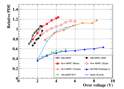
PDE
The PDE for Near UltraViolet (NUV) light is measured with a LED whose wavelength (370410 nm) approximately matches the scintillator emission peak. The LED intensity is adjusted in such a way that the average number of observed photo-electrons ranges between 0.5 and 1.0. The relative PDE is then calculated from P(N= 0) in accordance with Poisson statistics, and thus the measured PDE value does not include the effect of cross-talk nor after-pulsing. The result is shown in figure 4. The highest PDE is obtained with Hamamatsu S12572 model, with pitch cell. A more detailed description of noise and PDE studies can be found in [10].


Breakdown voltage versus temperature dependence
The BreakDown voltage (BD) versus temperature dependence has been measured by plotting the I-V characteristic of each SiPM at different temperatures (see figure 5) in the range , resulting in a linear dependence,

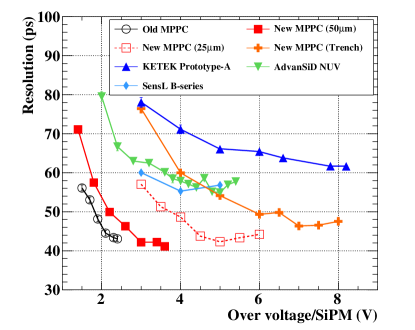
Time resolution
The basic setup for the timing resolution measurement is the same described above. A scintillator pixel with size mm3 is read-out on each side by an array of 3 SiPMs connected in series. SiPMs are coupled to the pixel with optical grease. A 35 ns coaxial cable (7.5 m) transports signals to amplifiers, simulating the final experimental conditions. Counters are excited by using a 90Sr -source, providing electrons with 2.2 MeV endpoint energy. An external Reference Counter (RC) made of a small piece of scintillator (BC422, size: mm3) coupled to a Hamamatsu S10362-33-050C SiPM is used for triggering purposes. The timing is extracted by applying a software constant fraction discrimination on the recorded waveform with discriminating fraction in the range depending on SiPM model.
The time resolution of the system is evaluated as the width of the distribution , being and the time measured by the reference counter and each SiPM array respectively. The RC resolution is evaluated ps and subtracted. The summary of the results is shown in figure 4 as a function of the applied over-voltage.
3.2 Scintillator comparison
Three types of ultra fast plastic scintillator from Saint-Gobain Crystals, BC418, BC420 and
BC422, were tested. The main characteristics of each scintillator are summarised in table
2, where also the characteristics of the BC404 are listed. The test was
performed using mm3 pixels. The best resolution is obtained
with BC422, the one with the fastest rise time.
| Properties | BC404 | BC418 | BC420 | BC422 |
| Light Yield (% Anthracene) | 68 | 67 | 64 | 55 |
| Rise Time (ns) | 0.7 | 0.5 | 0.5 | 0.35 |
| Decay time (ns) | 1.8 | 1.4 | 1.5 | 1.6 |
| Wavelength peak (nm) | 408 | 391 | 391 | 370 |
| Attenuation length (cm) | 140 | 100 | 110 | 8 |
| Measured resolution (ps) | - | 48 | 51 | 43 |
4 Beam test
In order to test the detector in experimental conditions similar to the final one and check the multiple hit scheme, a small prototype was built and tested at the Beam Test Facility (BTF) at the INFN Laboratori Nazionali di Frascati [11]. The BTF beam can be tuned in such a way to provide electrons with energy similar to the MEG signal ( MeV in our test) with average bunch multiplicity lower than 1. We decided to test counters equipped with both Hamamatsu and Advansid SiPMs, the ones with the best trade off between time resolution and temperature dependence.
4.1 Setup
We prepared two sets of pixel prototypes with BC418 scintillator, with mm3 sizes, equipped with Hamamatsu S12572-050C(X) (8 counters) and Advansid NUV (6 counters) SiPMs.
The pixels, wrapped with 3M Radiant Mirror Film,
are mounted on a moving stage that controls the movement in the plane perpendicular
to the beam. The whole system
is mounted on an optical bench enclosed in a shielded black box. The same reference
counter described in section 3.1 is placed along the beam trajectory in front
of the pixels. A lead glass calorimeter is placed behind the pixels for beam
monitoring. The whole system is aligned to the beam line by using a
laser tracker. Signals from SiPMs are fed into six DRS4 evaluation boards and sampled at 2.5 Gs/s.
4.2 Data analysis
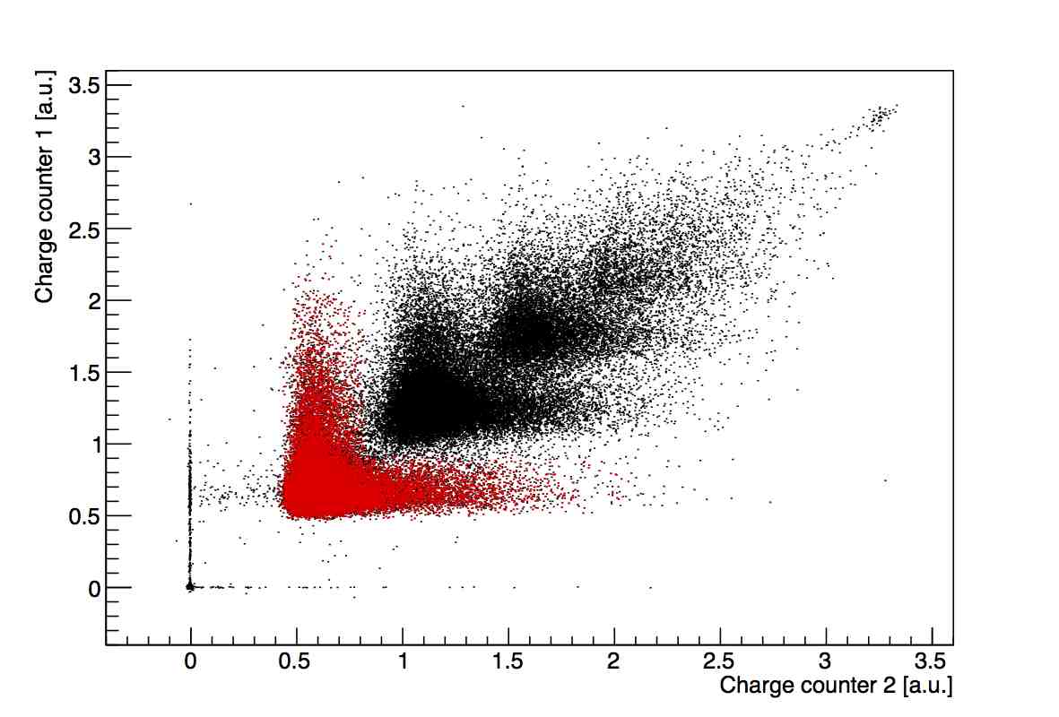
Charge analysis
Events are selected by cutting on the charge distribution of the first two pixels. An example of distribution is shown in figure 6, where the bunch multiplicity is clearly visible. Moreover, we applied also a cut on the reference counter charge spectrum, by selecting the events around the Landau peak of the charge distribution.
The timing resolution is then evaluated by taking the width of the distribution, defined in two different ways:
| (1) | |||||
| (2) |
where and is the time measured by the reference counter and by the pixels respectively, with and running on even and odd indices respectively. In formula 2 the sum is made over two different subgroups of pixels. In both cases, we can evaluate the timing resolution as a function of the number of hits used in the time averaging.
DRS calibrations
Dedicated runs were taken to evaluate the contribution from the electronics jitter. It was found to be 18.7 ps and 16.2 ps for pixels whose arrays are read-out by the same or different boards, respectively. The former contribution is higher because the jitters from channels on the same baord are fully correlated.
4.3 Results
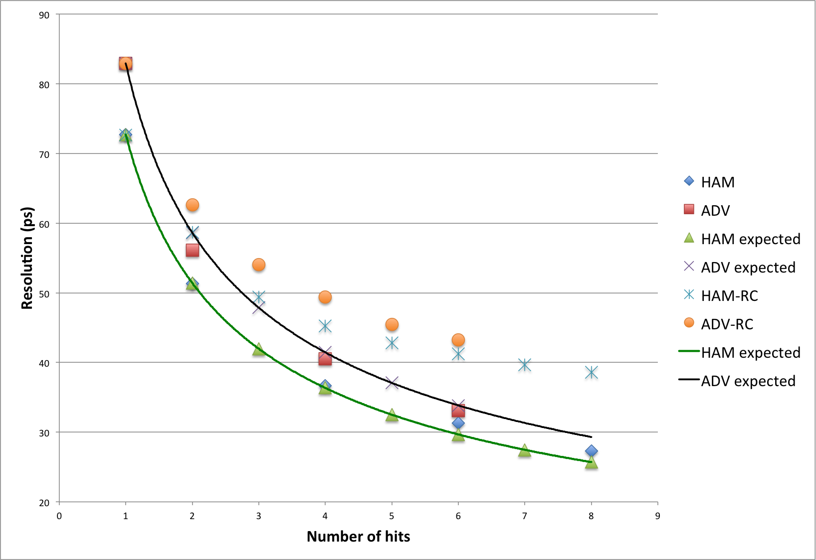
We checked the multiple hit scheme, relying on the approach in Eq. 1 as in section 3.1 studying the time resolution versus the number of hits. The contribution from the electronics, described in section 4.2 is taken into account. The RC resolution, which was checked with dedicated runs and found to be ps is also subtracted. As expected, the best result is obtained with the largest number of hits, with ps. Preliminary resolutions are summarised in figure 7, compared with the expected behaviour, which is also shown. An average is expected in the experiment.
5 Conclusions
We presented the R&D work on the upgrade of the Timing Counter for the MEG II experiment. The basic concepts of the new design, namely the good time resolution achievable with small scintillator counters read-out by SiPMs and the improvement of the overall time resolution by averaging the time measurements over multiple hits has been tested. Optimising the choice among different types of SiPM and scintillators leads to obtain extremely good time resolution with a single counter down to ps. A beam test performed at the Beam Test Facility in Frascati proved experimentally the multiple hit scheme. Analysis is still ongoing, a prelimiary resolution ps with eight counters is measured.
Acknowledgements.
The authors thank the Beam Test Facility crew, the mechanical and electronics workshops at INFN Section of Genova and the Paul Scherrer Institute detector group for their valuable help.References
- [1] J. Adam et al., [MEG Collaboration], New Constraint on the Existence of the Decay, Phys. Rev. Lett. 110 (2013) 201801.
- [2] A.M. Baldini et al., [MEG Collaboration], MEG upgrade proposal, [arXiv:1301.7225] [physics.ins-det].
- [3] J. Adam et al., [MEG Collaboration], The MEG detector for decay search, Eur. Phys. J. C 73 (2013) 2365.
- [4] M. De Gerone et al., Development and Commissioning of the Timing Counter for the MEG Experiment, IEEE Trans. Nucl. Sci. 59 (2012) 379.
- [5] M. De Gerone et al., The MEG timing counter calibration and performance, Nucl. Inst. Meth. A 638 (2011) 41.
- [6] A. Stoykov et al., A time resolution study with a plastic scintillator read out by a Geiger-mode Avalanche Photodiode, Nucl. Inst. Meth. A 695 (2012) 202.
- [7] W. Ootani, Development of Pixelated Scintillation Detector for Highly Precise Time Measurement in MEG Upgrade, Nucl. Inst. Meth. A 732 (2013) 146.
- [8] http://www.psi.ch/drs/evaluation-board
- [9] S. Ritt et al., Application of the DRS Chip for Fast Waveform Digitizing, Nucl. Inst. Meth. A 623 (2010) 486.
- [10] Y. Uchiyama [MEG collaboration], Nuclear Science Symposium Conference Record, IEEE, Seoul, Korea, 2013., in press
- [11] G. Mazzitelli et al., Commissioning of the DANE beam test facility, Nucl. Inst. Meth. A 515 (2003) 524.