Femtosecond 240-keV electron pulses from direct laser acceleration in a low-density gas
Abstract
We propose a simple laser-driven electron acceleration scheme based on tightly focused radially polarized laser pulses for the production of femtosecond electron bunches with energies in the few-hundreds-of-keV range. In this method, the electrons are accelerated forward in the focal volume by the longitudinal electric field component of the laser pulse. Three-dimensional test-particle and particle-in-cell simulations reveal the feasibility of generating well-collimated electron bunches with an energy spread of 5% and a temporal duration of the order of 1 fs. These results offer a route towards unprecedented time resolution in ultrafast electron diffraction experiments.
pacs:
41.75.Jv, 52.38.-r, 61.05.JThe development of high-power laser facilities all around the world has paved the way to the design of a new generation of laser-based electron accelerators. Recent experimental successes have shown that electrons may be accelerated to hundreds-of-MeV energies from high-intensity laser-plasma interactions Banerjee et al. (2012); Wang et al. (2012); Banerjee et al. (2013). Laser-driven electron accelerators are thus expected to offer a robust, compact, and low-cost alternative to conventional radio-frequency (rf) accelerators Malka et al. (2006).
While most studies have been concerned with the laser acceleration of electron bunches to energies ranging from several MeV to the GeV level Esarey et al. (2009), comparatively little work has been done at lower energies (e.g., Tokita et al. (2009); Uhliga et al. (2011); Payeur et al. (2012); He et al. (2013a); Breuer and Hommelhoff (2013)).
In fact, due to their large scattering cross section in comparison to x-rays, subrelativistic electrons find important applications in atomic and molecular imaging experiments Sciaini and Miller (2011). In the last few years, electrons at subrelativistic energies have been successfully used in time-resolved ultrafast electron diffraction (UED) experiments to study dynamical processes on the subpicosecond time scale Harb et al. (2008); Sciaini et al. (2009); Gao et al. (2013a). In the latter experiments, the electrons are generated from the illumination of a photocathode by a femtosecond laser pulse and are subsequently accelerated in a static electric field. Using this method, electron bunches with a duration between 200 and 350 fs and energy in the 50–100 keV range can be produced Sciaini and Miller (2011). In addition, using state-of-the-art rf cavities to invert the linear velocity chirp, the electron bunches can be compressed down to about 70 fs at the sample van Oudheusden et al. (2010), while the timing jitter between the laser and the rf electronics can be reduced to 30 fs with the time stamping method Gao et al. (2013b). Bunches of shorter durations (10 fs) have been predicted by replacing the static accelerator with a rf gun that accelerates the electrons at energies of a few MeV Han (2011). However, due to the reduced scattering cross section of relativistic electrons and other practical considerations, the 100–300 keV energy window is generally preferred for UED van Oudheusden et al. (2007).
Recently, laser-driven electron acceleration has been proposed as an alternative to static accelerator technology for UED experiments Tokita et al. (2009, 2010); He et al. (2013b). In principle, laser acceleration has several advantages He et al. (2013b): (i) the short wavelength of the accelerating field may lead to electron bunches with duration of the order of 10 fs or less; (ii) there is an intrinsic synchronization between the electron probe and the laser pump; (iii) using a gas medium, the electron source is self-regenerating and can thus be used for experiments at high repetition rates. In Tokita et al. (2010), 350-keV electron bunches were produced from a high-intensity laser-solid interaction and compressed down to 500 fs, while in He et al. (2013b), 100-keV bunches with a duration possibly under 100 fs, although not measured, were generated with a laser-wakefield accelerator. Subfemtosecond electron pulses are predicted in plasmas with ramp-up density profiles, but at relativistic energies Li et al. (2013).
In this Letter, we propose a simple direct acceleration scheme based on the use of tightly focused radially polarized laser pulses for the generation of electron bunches with unprecedentedly short duration in an energy range appropriate for UED applications. This method takes advantage of the strong longitudinal electric field at the beam center to accelerate the electrons from the focal region along the optical axis Varin et al. (2013). We demonstrate the feasibility of generating 240-keV, one-femtosecond electron pulses when the laser pulse is tightly focused in a low-density gas. The acceleration mechanism is first analyzed using a three-dimensional test-particle approach. We then investigate the limits of validity of these results using three-dimensional particle-in-cell (3DPIC) simulations with full ionization dynamics. We finally discuss how the proposed acceleration scheme could find applications in time-resolved UED experiments.
Ultrashort and tightly focused laser pulses must be modeled as exact solutions to Maxwell’s equations. We consider the lowest-order radially polarized laser field, namely a TM01 pulse, for which an exact closed-form solution is known April (2010); Marceau et al. (2012). In vacuum, the nonzero field components of a TM01 pulse traveling in the forward direction with its beam waist plane located at are given, in cylindrical coordinates (), by the following expressions:
| (1) | |||
| (2) | |||
| (3) |
where denotes the real part, is a constant amplitude, is the speed of light in vacuum, , , and with . The confocal parameter can be used to characterize the degree of paraxiality of the beam since it is related to the Rayleigh range at wavelength by Rodríguez-Morales and Chávez-Cerda (2004). The function is the inverse Fourier transform of the frequency spectrum of the pulse, which we assume to be Poisson-like Caron and Potvliege (1999):
| (4) |
where is a positive parameter related to the pulse duration, is the constant pulse phase, is the frequency of maximum amplitude, is the gamma function, and is the Heaviside step function. The fields given by Eqs. (1)–(3) may be produced by focusing a collimated radially polarized input beam with a parabolic mirror of large aperture April and Piché (2010).
Conceptually, our accelerator design simply consists of an ultrashort TM01 pulse that is strongly focused in a low-density gas target of uniform density . This configuration is very similar to the experimental setup recently used by Payeur et al. Payeur et al. (2012). To simulate the laser-driven electron acceleration, we perform three-dimensional simulations using the EPOCH PIC code Brady and Arber (2011). The fields given in Eqs. (1)–(3) are implemented in the code using the scattered-field formulation Taflove and Hagness (2005).
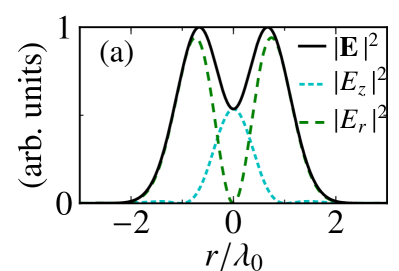
We consider a TM01 pulse characterized by and with an average power of GW and a dominant wavelength of nm. This gives a pulse with a full width at half maximum (FWHM) duration of 8.3 fs. The center of the pulse is set to reach the beam waist plane at fs. The spatiotemporal properties of the pulse in vacuum at the beam waist are illustrated in Fig. 1. The chosen laser parameters correspond to a regime accessible by current millijoule lasers that can operate at kHz repetition rate with carrier-envelope phase stabilization Mashiko et al. (2007); Chen et al. (2011).
In analogy to the standard normalized vector potential parameter Hartemann (2001), it is useful to introduce a normalized longitudinal field parameter Varin et al. (2013). At , the motion of a free electron in the longitudinal electric field becomes relativistic. Consequently, subcycle acceleration, i.e., the process in which the electron is accelerated by staying in phase with the laser field over a certain distance, starts to take place Varin et al. (2005). On the one hand, subcycle acceleration induces a strong longitudinal compression over a cloud of electrons, which promotes the formation of ultrashort electron bunches Varin and Piché (2006); Karmakar and Pukhov (2007). On the other hand, if the value of is too high, the electrons will acquire an energy that will be too great for any use in electron diffraction experiments. For the chosen laser pulse parameters, we have , a good tradeoff between the longitudinal compression induced by subcycle acceleration and the final kinetic energy of the electrons.
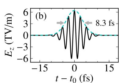
To investigate the acceleration dynamics, we adopt in the first place a three-dimensional test-particle approach in which all electrons are initially assumed to be free and space-charge effects are neglected. The electrons are initially distributed randomly in space according to a uniform distribution. As the laser pulse approaches the focal region, two main electron jets are formed: an annular electron jet is accelerated away from the optical axis under the influence of the radial electric field component, and a well-collimated electron bunch is accelerated in the forward direction by the longitudinal electric field component. Figure 2 illustrates the main properties of this on-axis electron bunch. At the instant the snapshots shown in Fig. 2 are taken, the interaction of the electron bunch with the laser pulse is already terminated. The divergence of the bunch is estimated to be 6 mrad, while its duration, given by the longitudinal extent of the bunch divided by the average velocity of the electrons, is of the order of 730 as. The energy distribution of the electron bunch, shown in Fig. 2(d), displays a well-defined maximum at keV with a small absolute energy spread of keV. Accelerating subfemtosecond pulses with radially polarized laser pulses using an infinite target is noteworthy, as previous techniques had to rely on nanometric targets and ultrarelativistic laser intensities () Varin and Piché (2006); Karmakar and Pukhov (2007).
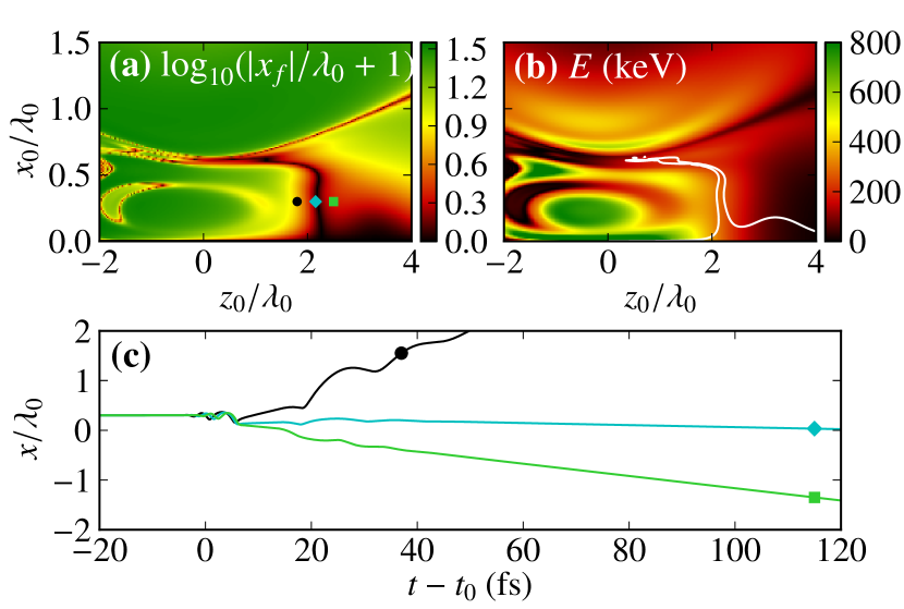
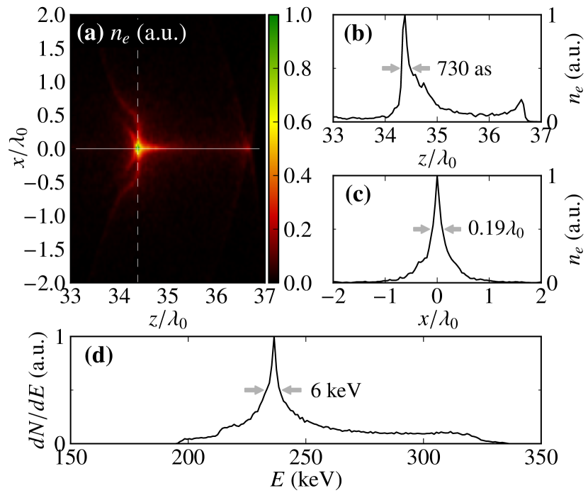
To get a better understanding of the formation of the ultrashort electron pulse reported in Fig. 2, it is instructive to identify the origin of the electrons of which it is made. Figure 3(a) maps the initial coordinates of a free electron in the plane to its final transverse coordinate. The most remarkable feature is the presence of a thin vertical band at extending from to that corresponds to electrons that remain within a distance of from the optical axis. Moreover, as shown in Fig. 3(b), this set of initial conditions is correlated with a region where the final kinetic energy of the electrons is extremely similar. Therefore, the formation of an ultrashort electron pulse originates from the acceleration of a thin disk of electrons located in a very restricted region of the infinite gas target. Electrons outside this thin disk region are either deflected away from the optical axis [see Fig. 3(c)] or gain little energy from the laser field. We emphasize that the acceleration process is sensitive to the carrier-envelope phase, a clear signature of direct acceleration that distinguishes our scheme from ponderomotive acceleration, which is a process independent of the laser pulse phase Stupakov and Zolotrev (2001). Here, substantial energy gains are possible because an asymmetry between consecutive positive and negative half field cycles is introduced by nonlinear relativistic effects, the ultrashort (few-cycle) pulse duration, and the strong field divergence ().
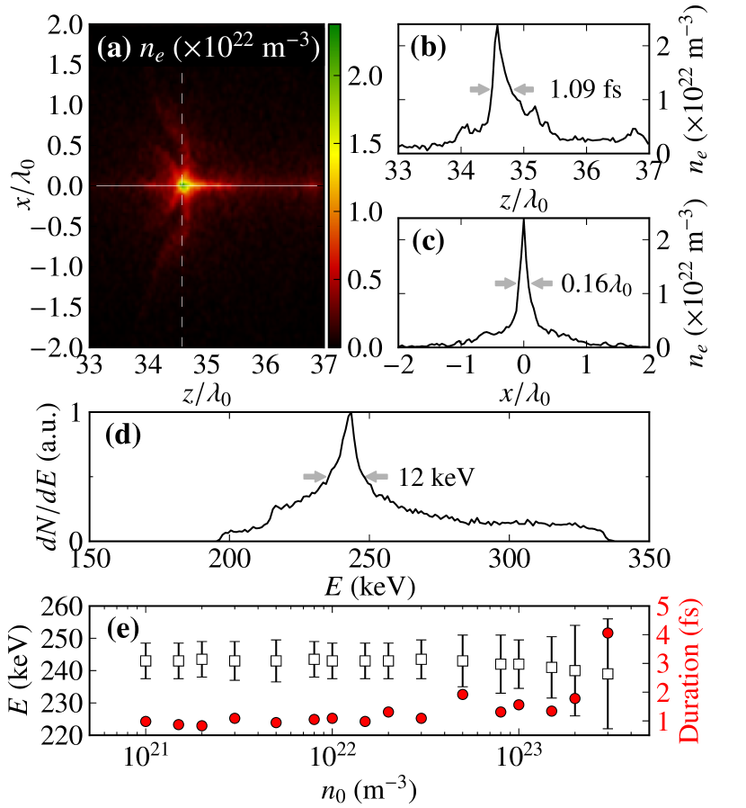
Having studied the acceleration mechanism in the single particle limit, we now proceed with a much more realistic 3DPIC approach. We assume that the initial target consists of a neutral hydrogen gas of uniform atomic density at room temperature. Multiphoton, tunnel, and barrier-suppression ionization are taken into account Lawrence-Douglas (2013). Figure 4(a)–(d) show the results of a simulation performed at an initial density of m-3 with the same laser parameters as in Fig. 2. The electron pulse produced from the hydrogen target possesses features very similar to that reported in Fig. 2. Its duration is slightly above one femtosecond, with a peak areal density and a total charge of Cm-2 and 1.1 fC, respectively. The charge was obtained by counting up the electrons located within a cylinder of radius extending from to [see Fig. 4(a)]. We calculate the fraction of the electrons within the FWHM of the longitudinal and radial density distribution to be 2.4%. We emphasize that due to the ionization dynamics, other elements than hydrogen might not be used to generate monoenergetic electron pulses. In fact, we have observed that 3DPIC simulations with helium yield an energy distribution with two distinct peaks (not shown).
In Fig. 4(e), we illustrate the variation of the main features of the electron pulse as a function of the initial density . Well-collimated, monoenergetic one-femtosecond pulses are observed up to densities of about m-3. Up to this density, the bunch charge increases linearly. As is raised above m-3, the electron pulse duration and its energy spread increase under the influence of electrostatic repulsion. At initial atomic densities of m-3 and above, the electron pulse is rapidly broadened by space-charge forces.
The possibility of generating femtosecond monoenergetic electron bunches suggests that the proposed acceleration scheme could offer an interesting avenue towards unprecedented time resolution in UED experiments. In this perspective, the transverse normalized emittance and the transverse coherence length are important parameters. The normalized emittance, which estimates the volume occupied by the electron beam in phase space, is given, in the direction, by , where denotes an average over the electrons in the bunch [18]. With the electrons from the same region that was used to calculate the bunch charge in Fig. 5(a) we get mmmrad, which compares favorably to state-of-the-art UED setups ( mmmrad [18,20]). The transverse coherence length is calculated with , where is the de Broglie wavelength and is the root-mean-square angular spread [18]. Here we obtain nm, which is too small for UED. Nevertheless, we estimate that filtering the electron pulses with a pinhole would remove the most divergent electrons and increase the transverse coherence length beyond 1 nm. With the remaining electrons per pulse (), an electron flux sufficient for time-resolved crystallography experiments would be possible at a kHz repetition rate (see, e.g., Baum et al. (2007)). Finally, we recall that for the proposed scheme —which is a subcycle laser process— the energy spread is intrinsically low (about 5%). Energy filtering as done in Tokita et al. (2010) might be beneficial, but is probably not necessary.
Still in connection with UED, we stress that free-space propagation is needed for the electron pulse to reach the sample, which causes spatiotemporal broadening. Nevertheless, the use of a strongly focused, rapidly diverging, laser pulse () could allow having the sample very close to the focus. With the available computational resources, we were able to simulate the propagation of the electron pulse for ps. Whereas the radius of the electron pulse did not change significantly, the pulse duration, after an initial transient behavior, increased linearly at the rate of fs/m. This asymptotic linear behavior is in agreement with existing theoretical models Siwick et al. (2002). It thus appears that pulse compression will be needed to keep the duration at the sample below 30 fs for a focus-sample distance larger than 1 mm. For state-of-the-art compression techniques see van Oudheusden et al. (2010); Tokita et al. (2010).
Finally, we emphasize that besides UED, the proposed acceleration scheme might also be of interest for electron injection into x-ray free electron lasers and staged (channel-guided) laser wakefield accelerators, as well as for the development of tabletop radiation sources. For those applications, relativistic energies are needed. Preliminary results for the actual acceleration scheme show that it would be possible to double the electron energy only by tuning the laser power, while preserving a good beam quality ( or less). The laser pulse parameters were not submitted to an intensive optimization process. Reaching the few-MeV range is the object of ongoing research.
Acknowledgements.
This research was supported by the Natural Sciences and Engineering Research Council of Canada (NSERC). The authors gratefully acknowledge Calcul Québec – Université Laval and Compute Canada for computational resources and support, as well as the EPOCH development team.References
- Banerjee et al. (2012) S. Banerjee, N. D. Powers, V. Ramanathan, I. Ghebregziabher, K. J. Brown, C. M. Maharjan, S. Chen, A. Beck, E. Lefebvre, S. Y. Kalmykov, et al., Phys. Plasmas 19, 056703 (2012).
- Wang et al. (2012) X. Wang, R. Zgadzaj, N. Fazel, S. A. Yi, X. Zhang, W. Henderson, Y.-Y. Chang, R. Korzekwa, H.-E. Tsai, C.-H. Pai, et al., AIP Conf. Proc. 1507, 341 (2012).
- Banerjee et al. (2013) S. Banerjee, S. Y. Kalmykov, N. D. Powers, G. Golovin, V. Ramanathan, N. J. Cunningham, K. J. Brown, S. Chen, I. Ghebregziabher, B. A. Shadwick, et al., Phys. Rev. ST – Accel. Beams 16, 031302 (2013).
- Malka et al. (2006) V. Malka, J. Faure, Y. Glinec, and A. F. Lifschitz, Phys. Trans. Roy. Soc. A 364, 601 (2006).
- Esarey et al. (2009) E. Esarey, C. B. Schroeder, and W. P. Leemans, Rev. Mod. Phys. 81, 1229 (2009).
- Tokita et al. (2009) S. Tokita, S. Inoue, S. Masuno, M. Hashida, and S. Sakabe, Appl. Phys. Lett. 95, 111911 (2009).
- Uhliga et al. (2011) J. Uhliga, C.-G. Wahlströma, M. Walczaka, V. Sundströma, and W. Fullagara, Laser Part. Beams 29, 415 (2011).
- Payeur et al. (2012) S. Payeur, S. Fourmaux, B. E. Schmidt, J.-P. MacLean, C. Tchervenkov, F. Légaré, M. Piché, and J.-C. Kieffer, Appl. Phys. Lett. 101, 041105 (2012).
- He et al. (2013a) Z.-H. He, B. Hou, J. A. Nees, J. H. Easter, J. Faure, K. Krushelnick, and A. G. R. Thomas, N. J. Phys. 15, 053016 (2013a).
- Breuer and Hommelhoff (2013) J. Breuer and P. Hommelhoff, Phys. Rev. Lett. 111, 134803 (2013).
- Sciaini and Miller (2011) G. Sciaini and R. J. D. Miller, Rep. Prog. Phys. 74, 096101 (2011).
- Harb et al. (2008) M. Harb, R. Ernstorfer, C. T. Hebeisen, G. Sciaini, W. Peng, T. Dartigalongue, M. A. Eriksson, M. G. Lagally, S. G. Kruglik, and R. J. D. Miller, Phys. Rev. Lett. 100, 155504 (2008).
- Sciaini et al. (2009) G. Sciaini, M. Harb, S. G. Kruglik, T. Payer, C. T. Hebeisen, F.-J. M. zu Heringdorf, M. Yamaguchi, M. H. von Hoegen, R. Ernstorfer, and R. J. D. Miller, Nature 458, 56 (2009).
- Gao et al. (2013a) M. Gao, C. Lu, H. Jean-Ruel, L. C. Liu, A. Marx, K. Onda, S.-Y. Koshihara, Y. Nakano, X. Shao, T. Hiramatsu, et al., Nature 496, 343 (2013a).
- van Oudheusden et al. (2010) T. van Oudheusden, P. L. E. M. Pasmans, S. B. van der Geer, M. J. de Loos, M. J. van der Wiel, and O. J. Luiten, Phys. Rev. Lett. 105, 264801 (2010).
- Gao et al. (2013b) M. Gao, Y. Jiang, G. H. Kassier, and R. J. D. Miller, Appl. Phys. Lett. 103, 033503 (2013b).
- Han (2011) J.-H. Han, Phys. Rev. ST – Accel. Beams 14, 050101 (2011).
- van Oudheusden et al. (2007) T. van Oudheusden, E. F. de Jong, S. B. van der Geer, W. P. E. M. O. Root, O. J. Luiten, and B. J. Siwick, J. Appl. Phys. 102, 093501 (2007).
- Tokita et al. (2010) S. Tokita, M. Hashida, S. Inoue, T. Nishoji, K. Otani, and S. Sakabe, Phys. Rev. Lett. 105, 215004 (2010).
- He et al. (2013b) Z.-H. He, A. G. R. Thomas, B. Beaurepaire, J. A. Nees, B. Hou, V. Malka, K. Krushelnick, and J. Faure, Appl. Phys. Lett. 102, 064104 (2013b).
- Li et al. (2013) F. Y. Li, Z. M. Sheng, Y. Liu, J. Meyer-ter-Vehn, W. B. Mori, W. Lu, and J. Zhang, Phys. Rev. Lett. 110, 135002 (2013).
- Varin et al. (2013) C. Varin, S. Payeur, V. Marceau, S. Fourmaux, A. April, B. Schmidt, P.-L. Fortin, N. Thiré, T. Brabec, F. Légaré, et al., Appl. Sci. 3, 70 (2013).
- April (2010) A. April, in Coherence and Ultrashort Pulse Laser Emission, edited by F. J. Duarte (InTech, 2010), pp. 355–382.
- Marceau et al. (2012) V. Marceau, A. April, and M. Piché, Opt. Lett. 37, 2442 (2012).
- Rodríguez-Morales and Chávez-Cerda (2004) G. Rodríguez-Morales and S. Chávez-Cerda, Opt. Lett. 29, 430 (2004).
- Caron and Potvliege (1999) C. F. R. Caron and R. M. Potvliege, J. Mod. Opt. 46, 1881 (1999).
- April and Piché (2010) A. April and M. Piché, Opt. Express 18, 22128 (2010).
- Brady and Arber (2011) C. S. Brady and T. D. Arber, Plasma Phys. Control. Fusion 53, 015001 (2011).
- Taflove and Hagness (2005) A. Taflove and S. C. Hagness, Computational Electrodynamics: The Finite-Difference Time-Domain Method (Artech House, 2005), 3rd ed.
- Mashiko et al. (2007) H. Mashiko, C. M. Nakamura, C. Li, E. Moon, H. Wang, J. Tackett, and Z. Chang, Appl. Phys. Lett. 90, 161114 (2007).
- Chen et al. (2011) X. Chen, A. Malvache, A. Ricci, A. Jullien, and R. Lopez-Martens, Laser Phys. 21, 198 (2011).
- Hartemann (2001) F. V. Hartemann, High-Field Electrodynamics (CRC Press, 2001).
- Varin et al. (2005) C. Varin, M. Piché, and M. A. Porras, Phys. Rev. E 71, 026603 (2005).
- Varin and Piché (2006) C. Varin and M. Piché, Phys. Rev. E 74, 045602(R) (2006).
- Karmakar and Pukhov (2007) A. Karmakar and A. Pukhov, Laser Part. Beams 25, 371 (2007).
- Stupakov and Zolotrev (2001) G. V. Stupakov and M. S. Zolotorev, Phys. Rev. Lett. 86, 5274 (2001).
- Lawrence-Douglas (2013) A. Lawrence-Douglas, Ph.D. thesis, University of Warwick (2013).
- Baum et al. (2007) P. Baum, D.-S. Yang, and A. H. Zewail, Science (New York, N.Y.) 318, 788 (2007).
- Siwick et al. (2002) B. J. Siwick, J. R. Dwyer, R. E. Jordan, and R. J. D. Miller, J. Appl. Phys. 92, 1643 (2002).