Magnetic structure map for face-centered tetragonal iron: appearance of a new collinear spin structure
Abstract
For fcc and tetragonal distorted fct iron a large number of magnetic configurations as a function of crystal structural parameters were studied by means of density functional theory concepts. The stability of magnetic structures was defined by the magnetic re-orientation energy as the difference of the total energy of configuration and that of the fcc ferromagnetic state. The Cluster Expansion technique was applied to six volumes deriving for more than 90.000 collinear spin structures at each volume. Structures with low were tetragonally distorted according to a two-dimensional mesh defined by volume per atom and ratio. At each mesh point for all collinear structures were compared to results for spin spirals (SS) which were calculated on a grid of propagation directions, and then the lowest defined the magnetic structure map. Three local minima were identified and for each of the minima SS were calculated on a fine grid of propagation vectors. At the minimum with Å 3 and a hitherto unknown simple collinear spin structure with four atoms per fct unit cell was the most stable one. It consists of two atoms with anti-ferromagnetically ordered local moments of and of two atoms with zero local moment.
pacs:
75.25.-j, 75.30.-m,71.15.Mb,71.15.NcThe intriguing magnetic orderings of fcc-related phases of Fe arrested particular attention. Although a large number of experimental as well as theoretical studies were performed it is still an open question, if unknown phases exist. Indeed we detected a new simple collinear magnetic ordering, which includes atoms with zero local moment.
We search for new structures by means of a map describing magnetic ordering versus volume per atom and ratio of tetragonally distorted fcc Fe. Thereby scanning a large configuration space for magnetic orderings for which we developed a new strategy based on spin dependent total energies as derived by density functional theory (DFT) calculations. We will address the fcc-related phases as fct Fe as tetragonal distortion is very important for the stabilization of magnetic structures.
Experiments were done on thin-films Pescia et al. (1987); Darici et al. (1987); Liu et al. (1988); Macedo and Keune (1988); Stampanoni (1989); Lu et al. (1989); Landskron et al. (1991); Wutting and Thomassen (1993) and precipitates Tsunoda (1989); Tsunoda et al. (1993, 2007). The fct structure was enforced by a host material or substrate with fcc structure (e.g. Cu). Diffraction measurements on precipitatesTsunoda (1989); Tsunoda et al. (1993) observed a helical spin spiral (SS) which stimulated DFT studies. Knöpfle et al. (2000); Spišák and Hafner (2000, 2002); Sjöstedt and Nordström (2002); Marsman and Hafner (2002); Abrikosov et al. (2007) Marsman et al.Marsman and Hafner (2002) found the experimentally claimed SS when the fcc structure was tetragonally distorted. This was confirmed by a recent experiment on precipitates.Tsunoda et al. (2007) Low-energy electron diffraction (LEED) on thin-films was inconclusive suggesting a range of hitherto unresolved magnetic configurations. Pescia et al. (1987); Liu et al. (1988); Macedo and Keune (1988); Stampanoni (1989); Wutting and Thomassen (1993)
First, a large set of collinear magnetic configurations with fcc lattice was sifted through according to Fig. 1. This was done by Cluster ExpansionSanchez et al. (1984); Ferreira et al. (1989); Müller (2003); Lerch et al. (2009) (CE) at several s. Then, structures were selected and tetragonally distorted according to a two-dimensional mesh defined by and (see Fig. 3). For each mesh point the magnetic re-orientation energy (see caption of Fig. 1) for selected collinear structures were compared to for SSs with a selected set of propagations and by that three local minima were found. For each minimum SSs were re-calculated on a fine grid of propagations. Finally, the magnetic structure with the lowest is indicated on the two dimensional structure map. Refs. Singer et al., 2011; Dietermann et al., 2012; Fähnle and Zhang, 2013 presented a general multi-spin-configuration CE, which includes also SSs. Such a general concept however is expected to be computationally hardly feasible and no applications to realistic cases have been published until now. Furthermore, it is unclear how distortions might be included, which however, are important.
DFT calculations for spin-dependent total energies were done by VASPKresse and Furthmüller (1996); Kresse and Joubert (1999) within the projector augmented wave method.Blöchl (1994) The generalized gradient parametrization of Ref.Perdew et al., 1996 was chosen and the basis set size cutoff was 400 eV. The Brillouin zone integration was made by a Gaussian smearing technique and the broadening of eV on a Monkhorst and Pack Monkhorst and Pack (1976) -point mesh for a one atom unit cell. For larger cells the mesh was scaled down accordingly. SSs were calculated by means of the generalized Bloch theorem.Kübler (2000); Hobbs et al. (2000); Marsman and Hafner (2002) The local magnetic spin moments were determined for a sphere of radius Å .
Utilizing the package UNCLE.Lerch et al. (2009) a binary CE Sanchez et al. (1984); Ferreira et al. (1989); Müller (2003); Lerch et al. (2009) was performed for collinear up/down spin ordering on an fcc parent lattice at the six volumes per atom, Å3 while atomic positions and cell shape were not relaxed. The condition for accepting a given spin configuration for the CE was that the local moments were . The CE fitting was done by least-square minimizationLu et al. (1991) checking its quality in terms of the (leave one out) cross validation score (CVS) van de Walle and Ceder (2002). A genetic algorithm was applied for the selection of clusters up to six-body interactions. Due to spin interchangeability is symmetric with respect to the total spin polarization (see Fig. 1).
Discussing the CE calculations we focus only on Å3. The total number of DFT input structures was 90 and the configuration search was done for up to 16 atoms per unit cell, resulting in 93672 magnetic configurations.
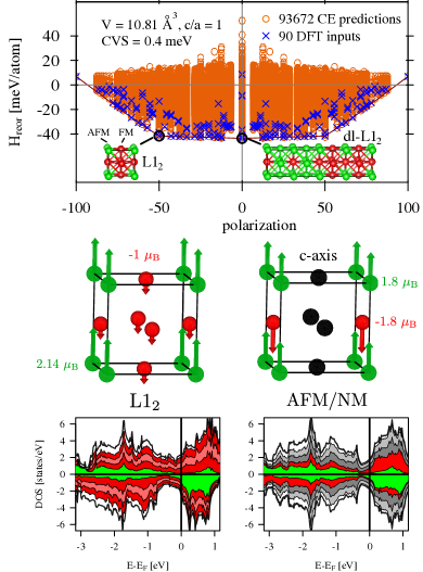
The CE derived ground states strongly depend on volume. At larger volumes Å3 the most favorable ordering is the double-layer anti-ferromagnetic (dl-AFM) configuration,Spišák and Hafner (2000, 2002); Marsman and Hafner (2002); Abrikosov et al. (2007) which is unstable under tetragonal distortion and monoclinic shearing.Spišák and Hafner (2002); Marsman and Hafner (2002) Its stability in comparison to SSs is disputed.Sjöstedt and Nordström (2002); Abrikosov et al. (2007) Remarkably, at the smaller volume of Å3 a ferrimagnetic configuration resembling the crystallographic L12 (Cu3Au) structure in combination with a very similar double-layer L12-like (dl-L12) is found to be stable. As sketched in Fig. 1 L12 consists of magnetic moments of distinctly different sizes: a large moment with and three small moments , resulting in the total moment of per unit cell.
By tetragonal distortion the moments of dl-AFM ordering and other studied anti-ferromagnetic (AFM) configurations remain rather unchanged. However, for L12 the low moments in the ferromagnetic plane collapse resulting in a peculiar mixed anti-ferromagnetic/ nonmagnetic (AFM/NM) spin configuration, in which AFM planes with moments of alternate with NM planes (see Fig.1). Remarkably, even for and Å3 the AFM/NM configuration is more stable by one meV/atom than cubic L (see Fig. 2).
Focusing on SSs, of interest are spirals with propagations in direction , and spirals in direction . The following propagations were considered: , , , , and whereby defines the lattice parameter and the tetragonal distortion. For and the parameter varies between and for ,, its range is . Because of the higher symmetry of the fcc latice the directions are reduced to and , accordingly. In previous DFT studies Knöpfle et al. (2000); Spišák and Hafner (2000, 2002); Marsman and Hafner (2002); Sjöstedt and Nordström (2002); Abrikosov et al. (2007), SSs with for directions , , and for directions and the related directions , , were found to be in contest. At each point of the magnetic structure map the choice of propagations was made as just discussed. At each of the three energy minima of the map (see Fig.3 and Table 1) a much finer scan of -vectors in steps of was made. In addition, the accuracy of the generalized Bloch theorem in comparison to suitable supercell calculations was tested and found to be sufficient: the differences of total energies between both approaches were always meV/atom.
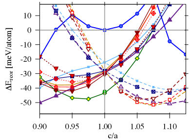
For all investigated spin structures Fig. 2 depicts depending on . For each point and configuration the energy was minimized with regards to . The two regions and are clearly distinguishable by the most stable spin structures. For SS configurations , propagating along the axis and collinear structures AFMZ are favored. For clearly one structure is most stable, namely the newly found AFM/NM ordering (see Fig. 1).
Discussing the volume dependency the collinear configurations AFM, AFM/NM, L12 and the non-collinear SSs , , have their respective minima of in the range of Å3. For dl-AFM and the SSs , the minimum of appears at the larger volumes Å3. A ferromagnetic low-moment (LM) phase with a moment of appears at the minimum with Å3 and . For the LM ferromagnetic configuration is more favorable than the two high-moment (HM) ferromagnetic phases which are a) an fct phase with and its minimum at Å3, , and b) the HM bcc phase with at ) and Å3 (see Table 1).
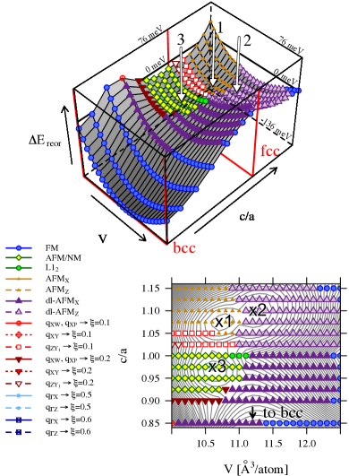
The centerpiece of our work is shown in Fig. 3, presenting the structure map of magnetic phase stability as a function of volume and ratio. It combines the results for collinear orderings and SSs in terms of the lowest . Three local minima were found (see Table 1) as marked by x1, x2, and x3 (see Fig. 3). The minima x1 and x2 occur for whereas x3 is found for . If only SSs are considered the two local minima SS1 and SS2 appear as listed in Table 1. SS1 with has its minimum for whereas for SS2 with the minimum is for .
| mag. ord. | ||||
|---|---|---|---|---|
| [Å3] | [meV/atom] | |||
| x1 | AFM | 10.7 | 1.075 | -52 |
| x2 | dl-AFM | 11.2 | 1.100 | -51 |
| x3 | AFM/NM | 10.6 | 0.975 | -48 |
| SS1 | 10.7 | 1.075 | -51 | |
| SS2 | 10.7 | 0.950 | -42 | |
| FM (LM) | 10.5 | 1.000 | 0 | |
| L12 | 10.7 | 1.000 | -42 | |
| FM (HM) | 11.7 | 1.175 | -25 | |
| NM | 10.2 | 1.000 | 19 | |
| FM bcc Fe | 11.3 | 1/ | -136 |
Minimum x1 with Å3 represents the collinear AFM configuration. However, Table 1 (lines one and four) shows that the energy difference between AFM and SS1 with is only 1 meV. In fact, a small orthorhombic distortion with stabilizes SS1 by 0.2 meV/atom as predicted by Marsman et al.Marsman and Hafner (2002) and confirmed experimentally by Tsunoda et al..Tsunoda et al. (2007) For SS1 is always more favorable than AFM but for AFM is more favorable than any SS1 with and , as stated in Ref. Marsman and Hafner, 2002.
Minimum x2 with Å3 belongs to dl-AFM. At these coordinates the closest competing configuration is the SS with which is less stable by 8 meV/atom. This result was confirmed by calculating SSs for . For dl-AFM no atomic relaxation were considered, which would further lower . Therefore, in contrast to Refs. Abrikosov et al., 2007; Sjöstedt and Nordström, 2002 we exclude that any SS will be more stable than dl-AFM at volumes larger than 11Å3. The collinear configurations dl-AFM and dl-AFM are the dominating structures but they are unstable against monoclinic shearing. Spišák and Hafner (2002); Marsman and Hafner (2002)
Minimum x3 corresponding to the AFM/NM configuration with its peculiar mixture of AFM and NM planes (see Fig. 1) is the shallowest one (see Table 1). Nevertheless, it is the only configuration with a local minimum for , namely Å3. Supposedly, the AFM/NM configuration indicates formation of an SS. However, the corresponding SSs with propagations and are very unfavorable for this particular (see Fig. 2): AFM/NM is by 9 meV/atom more stable than the closest non-collinear ordering SS2 with . Varying at the same and shows that indeed SS2 with is the most favorable SS. Presumably the AFM/NM configuration has been detected previously by LEED measurements at 300K on thin films consisting of 10 to 12 mono-layers. Lu et al. (1989); Darici et al. (1987) Subsequent LEED experiments Landskron et al. (1991); Wutting and Thomassen (1993) observed a distinct orthorhombic distortion and volume expansion Wutting and Thomassen (1993) when the samples were further cooled down resembling a transition from minimum x3 to x1. The analysis of the experimental results was rather inconclusive with respect to the magnetic ordering, and a range of magnetic configurations from nonmagnetic to ferromagnetic to anti-ferromagnetic orderings were suggested. Pescia et al. (1987); Liu et al. (1988); Macedo and Keune (1988); Stampanoni (1989); Wutting and Thomassen (1993) These observations, while seemingly contradicting each other support our finding of the AFM/NM configuration.
The stability of AFM/NM compared to L12 is illustrated by the density of states (DOS) (see Fig. 1): the values of the DOS at Fermi energy, for both spin channels of L12 is larger by 40% than for AFM/NM (see also Supplementary B). For L12 the spin up and down DOS is not symmetric and the total moment is not zero. This is in contrast to AFM/NM for which the total moment is zero because for each layer perpendicular to the -axis the local moments ) either cancel or are perfectly zero. Performing studies with different spin splits (see Supplementary B) it turns out that the stability of AFM/NM is due to its lowest . By orthorhombic distortion a structure is stabilized for which the magnetically dead atoms accumulate finite local moments. Its crystal structure resembles the structure at minimum x1 (see Supplementary A).
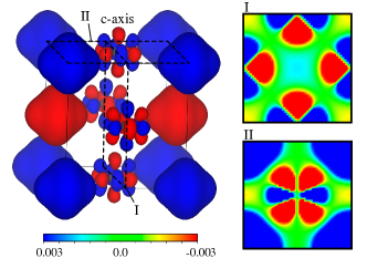
The peculiarity of AFM/NM is illustrated by Fig.4 showing that the magnetization density around the positions of the magnetically dead atoms is strongly spin polarized in a symmetric manner such that the resulting local moments are zero. This symmetry property remains even when the AFM/NM structure is tetragonally distorted according to Fig. 1. Consequently, AFM/NM is the most stable spin ordering for .
Summarizing, our extensive search for magnetic configurations of fct Fe in terms of a magnetic structure map predicts a range of magnetic orderings. In particular, on this energy landscape depending on volume per atom and ratio a hitherto unknown and simple collinear anti-ferromagnetic ordering with magnetically dead Fe atoms was found. We believe by that the riddle concerning magnetic ordering and structure as posed by experiment is finally solved.
Acknowledgements.
Work was supported by the Austrian Science Fund FWF within the Special Research Program VICOM (Vienna Computational Materials Laboratory, Project No. F4110). Calculations were done on the Vienna Scientific Cluster (VSC).References
- Pescia et al. (1987) D. Pescia, M. Stampanoni, G. L. Bona, A. Vaterlaus, R. F. Willis, and F. Meier, Physical Review Letters 58, 2126 (1987).
- Darici et al. (1987) Y. Darici, J. Marcano, H. Min, and P. A. Montano, Surface Science 182, 477 (1987).
- Liu et al. (1988) C. Liu, E. R. Moog, and S. D. Bader, Phys. Rev. Lett. 60, 2422 (1988).
- Macedo and Keune (1988) W. A. A. Macedo and W. Keune, Physical Review Letters 61, 475 (1988).
- Stampanoni (1989) M. Stampanoni, Applied Physics A 49, 449 (1989).
- Lu et al. (1989) S. H. Lu, J. Quinn, D. Tian, F. Jona, and P. M. Marcus, Surface Science 209, 364 (1989).
- Landskron et al. (1991) H. Landskron, G. Schmidt, K. Heinz, K. Müller, C. Stuhlmann, U. Beckers, M. Wutting, and H. Ibach, Surface Science 256, 115 (1991).
- Wutting and Thomassen (1993) M. Wutting and J. Thomassen, Surface Science 282, 237 (1993).
- Tsunoda (1989) Y. Tsunoda, J. Phys.: Condens. Matter 1, 10427 (1989).
- Tsunoda et al. (1993) Y. Tsunoda, Y. Nishioka, and R. M. Nicklow, Journal of Magnetism and Magnetic Materials 128, 133 (1993).
- Tsunoda et al. (2007) Y. Tsunoda, H. Nogami, and M. Takasaka, Physical Review B 76, 054419 (2007).
- Knöpfle et al. (2000) K. Knöpfle, L. M. Sandratskii, and J. Kübler, Physical Review B 62, 5564 (2000).
- Spišák and Hafner (2000) D. Spišák and J. Hafner, Physical Review B 61, 16129 (2000).
- Spišák and Hafner (2002) D. Spišák and J. Hafner, Physical Review Letters 88, 056101 (2002).
- Sjöstedt and Nordström (2002) E. Sjöstedt and L. Nordström, Physical Review B 66, 014447 (2002).
- Marsman and Hafner (2002) M. Marsman and J. Hafner, Physical Review B 66, 224409 (2002).
- Abrikosov et al. (2007) I. A. Abrikosov, A. E. Kissavos, F. Liot, B. Alling, S. I. Simak, O. Peil, and A. V. Ruban, Physical Review B 76, 014434 (2007).
- Sanchez et al. (1984) J. Sanchez, F. Ducastelle, and D. Gratias, Physcia A 128, 334 (1984).
- Ferreira et al. (1989) L. G. Ferreira, S.-H. Wei, and A. Zunger, Physical Review B 40, 3197 (1989).
- Müller (2003) S. Müller, Journal of Physics: Condensed Matter 15, R1429 (2003).
- Lerch et al. (2009) D. Lerch, O. Wieckhorst, G. Hart, R. Forcade, and S. Müller, Modelling Simul. Mater. Sci. Eng. 17, 055003 (2009).
- Singer et al. (2011) R. Singer, F. Dietermann, and M. Fähnle, Physical Review Letters 107, 017204 (2011).
- Dietermann et al. (2012) F. Dietermann, L. Sandratskii, and M. Fähnle, Journal of Magnetism and Magnetic Materials 324, 2693 (2012).
- Fähnle and Zhang (2013) M. Fähnle and S. Zhang, Journal of Magnetism and Magnetic Materials 326, 232 (2013).
- Kresse and Furthmüller (1996) G. Kresse and J. Furthmüller, Phys. Rev. B 54, 11169 (1996).
- Kresse and Joubert (1999) G. Kresse and D. Joubert, Phys. Rev. B 59, 1758 (1999).
- Blöchl (1994) P. E. Blöchl, Phys. Rev. B 50, 17953 (1994).
- Perdew et al. (1996) J. P. Perdew, K. Burke, and M. Ernzerhof, Phys. Rev. Lett. 77, 3865 (1996).
- Monkhorst and Pack (1976) H. Monkhorst and J. Pack, Phys. Rev. B 13, 5188 (1976).
- Kübler (2000) J. Kübler, Theory of Itinerant Electron Magnetism (Oxford University Press, Oxford, 2000).
- Hobbs et al. (2000) D. Hobbs, G. Kresse, and J. Hafner, Physical Review B 62, 11556 (2000).
- Lu et al. (1991) Z. W. Lu, S.-H. Wei, A. Zunger, S. Frota-Pessoa, and L. G. Ferreira, Physical Review B 44, 512 (1991),).
- van de Walle and Ceder (2002) A. van de Walle and G. Ceder, Journal of Phase Equilibria 23, 348 (2002).
- Momma and Izumi (2011) K. Momma and F. Izumi, J. Appl. Crystallogr. 44, 1272 (2011).