Fast E-sail Uranus entry probe mission
Abstract
The electric solar wind sail is a novel propellantless space propulsion concept. According to numerical estimates, the electric solar wind sail can produce a large total impulse per propulsion system mass. Here we consider using a 0.5 N electric solar wind sail for boosting a 550 kg spacecraft to Uranus in less than 6 years. The spacecraft is a stack consisting of the electric solar wind sail module which is jettisoned roughly at Saturn distance, a carrier module and a probe for Uranus atmospheric entry. The carrier module has a chemical propulsion ability for orbital corrections and it uses its antenna for picking up the probe’s data transmission and later relaying it to Earth. The scientific output of the mission is similar to what the Galileo Probe did at Jupiter. Measurements of the chemical and isotope composition of the Uranian atmosphere can give key constraints to different formation theories of the Solar System. A similar method could also be applied to other giant planets and Titan by using a fleet of more or less identical probes.
keywords:
electric solar wind sail , Uranus entry probe missionurl]http://www.electric-sailing.fi
1 Introduction
The electric solar wind sail (E-sail) is a newly discovered concept of propelling an interplanetary spacecraft by employing the thrust produced by the natural solar wind plasma stream [1, 2]. According to numerical performance estimates [3], the E-sail has a high ratio of produced total impulse per propulsion system mass. The E-sail can be used for many solar system propulsive tasks, including inner planets [4], asteroid rendezvous and sample return missions [5, 6], asteroid deflection [7], various continuous thrust non-Keplerian orbits [8] and flyby or orbiter missions to outer planets [9, 10].
The subject of the paper is a preliminary analysis on how to deliver an atmospheric probe to Uranus reasonably fast (less than 6 years) and at low cost in comparison to traditional outer planet missions. The main objective is to make the case for conducting NASA’s Galileo probe type measurements at Uranus, i.e. to measure the chemical and isotopic composition of the atmosphere. A second goal of the paper is to describe, although with less depth than for Uranus, the case for sending a similar probe using the same novel propulsion technique to all giant planets and possibly Titan.
2 Why an atmospheric probe to Uranus?
Measuring the chemical and isotope composition of giant planet atmospheres is important because such measurements can constrain models of the early history of the Solar System [11]. Thus far, only the Jovian atmosphere has been directly probed in situ. Some presently favoured models of Solar System history such as the Nice model [12] and its later variants [13] predict that the giant planets formed originally at different solar distances than where they are located nowadays. Because the temperature of the protoplanetary disk depended on the solar distance, the models give predictions of the chemical and isotope composition of the giant planet atmospheres. However, many of these predictions can only be checked against measurements by in situ probing of the planetary atmospheres.
An early analysis of Uranus and Neptune entry probes was made relatively soon after the NASA’s Voyager flybys [14]. More recently, a planetary entry probe engineering study for Venus, Saturn, Uranus and Neptune was carried out at ESA’s Concurrent Design Facility [15].
All giant planet atmospheres should be eventually probed and the most effective way of doing so might be by using a fleet of identical or rather identical E-sail equipped probes, each one targeted to its own planet. However, in this paper we concentrate on Uranus. Once a Uranus mission has been designed, the other cases can be obtained as follows:
-
1.
Jupiter has already been probed by NASA’s Galileo spacecraft. If a fleet mission to all giant planets is made, it might be worthwhile to measure Jupiter again with instruments identical to those used on the other planets.
-
2.
Except for somewhat higher entry speed which requires somewhat heavier heat shield, Saturn mission is technically easier than Uranus because of shorter traveltime and shorter telemetry distance. If an E-sail based mission to Uranus proves to be feasible, a Saturn mission would be expected to be feasible, too.
-
3.
If a fleet mission to all giant planets is conducted, it might be a good idea to also add Titan to the set of targets. Similar considerations to Saturn apply to Titan except that the heat shield requirements are smaller because of lower entry speed due to less massive target.
-
4.
A Neptune mission would be, in principle, similar to Uranus mission except for longer traveltime and longer telemetry distance. However, in the mission architecture that we will analyse in this paper, the telemetry distance is not a major cost factor because the total probe data volume is modest and because the data can be downlinked to Earth by the carrier module at a low bitrate.
Hence, by analysing a Uranus entry probe mission explicitly we can take the first step not only for designing a Uranus probe mission, but also assessing the mission requirements for all the giant planets.
We do not consider orbiter missions in this paper because regardless of the employed propulsion technology, orbiter missions with their more complex and comprehensive scientific payloads typically fall into a significantly higher cost category than atmospheric probe missions. The other reason is that a fast E-sail trajectory may be relatively speaking less feasible for an orbiter mission, because in case of Uranus and Neptune, one would need a significant amount of chemical propellant for the planetary orbit insertion or alternatively one should rely on aerocapture whose technical readiness level is lower than that of chemical propulsion.
3 E-sail Uranus entry probe mission
Our proposed E-sail Uranus entry probe mission consists of three modules which are initially stacked together: the E-sail module, the carrier module and the entry module. The entry module is composed of the atmospheric probe inside a heatshield. The stack is initially launched to Earth escape orbit by a conventional booster. The E-sail module accelerates the stack to Uranus intercepting trajectory. The carrier module performs the necessary orbital corrections to fly by Uranus and to collect the data transmitted by the atmospheric probe. In more detail, the mission proceeds according to the following steps:
-
1.
The stack is launched to Earth escape orbit by a conventional booster. Any escape orbit (i.e. any orbit with non-negative specific energy parameter C3) is suitable for the purpose. For the E-sail to work, it is required to be in the solar wind.
-
2.
The E-sail module accelerates the stack to a trajectory towards Uranus.
-
3.
The E-sail module is abandoned approximately at Saturn distance.
-
4.
The carrier module uses chemical propulsion (in this paper baselined as green monopropellant) for orbital corrections.
-
5.
About 13 million km (8 days) before Uranus, the carrier module detaches itself from the entry module and makes a km/s transverse burn so that it passes by the planet at km distance, safely outside the ring system. Also a slowing down burn of the carrier module may be needed to optimise the link geometry during flyby.
-
6.
Protected by the heat shield, the entry module enters into atmosphere.
-
7.
A parachute is deployed and the heat shield is separated.
-
8.
The probe falls under parachute in Uranus atmosphere, makes scientific measurements and transmits data to the high gain antenna of the carrier which flies by at km distance.
-
9.
After exiting Uranus environment, the carrier redirects its high gain antenna towards Earth to transmit the stored probe science data.
The communication frequency between probe and carrier cannot be set too high because of the attenuation and scattering of the radio signal caused by atmospheric gases and clouds. The frequency selection trade-off study is outside the scope of this paper, but using the same values as Galileo probe should be a good starting point. The Galileo probe worked until 20 bar pressure and used 1.39 GHz frequency to transmit 3.5 Mbit of data volume to the orbiter’s 1.1 m receiving antenna [16]. The mass of the Galileo orbiter hardware dedicated to receiving and relaying the probe data was 23 kg [16]. In our case, communication with Earth would probably be done at higher frequency although using the same m antenna dish. A one metre dish enables only slow communication with Earth from Uranus distance, but this is not a problem since the carrier spacecraft has plenty of time to send the data after passing by the planet.
Table 1 shows the top-level mass budget. The 0.5 N E-sail module component masses (Table 2) are adopted from the last column of Table 3 of Ref. [3]. The design uses 50 tethers, each of which is 18 km long, and made of 50 m diameter aluminium base wire and three 25 m loop wires whose purpose is to prevent the tether from breaking even when micrometeoroids randomly cut its individual wires [17]. We assume that the auxiliary tethers are made of 7.6 m thickness kapton which is currently an ITAR-restricted product. The purpose of the auxiliary tethers is to connect together the tips of the main tethers to ensure dynamical stability of propulsive flight [2]. Using ITAR-free 12.6 m kapton would increase the mass of the E-sail module by 12.1 kg. Regardless of the used thickness, it could be possible to save some mass by using a more aggressive punching pattern for the auxiliary tethers. We included a 20% E-sail module system margin.
| E-sail module | 150 kg |
| Carrier module (wet) | 150 kg |
| Entry module | 256 kg |
| Total | 556 kg |
| 0.5 N thrust at 1 au from the Sun | |
| 0.9 mm/s2 characteristic acceleration | |
| 5018 km main tethers (m basem loop wire) | 10.3 kg |
| Main tether reels | 11.4 kg |
| Electron guns | 1.59 kg |
| 540 W/40 kV high voltage source | 10.6 kg |
| Tether cameras and E-sail control electronics | 1.48 kg |
| 50 Remote Units | 49.3 kg |
| 7.6 m cm 50% punched kapton auxiliary tether ring | 18.2 kg |
| E-sail module structural | 22 kg |
| E-sail system margin +20% | 25 kg |
| E-sail module total | 150 kg |
For passive dynamical stability in the E-sail deployment and cruise phase, the inertial moment of the spacecraft stack should be largest along the spin axis. In other words, the spacecraft stack should resemble a disk or relatively flat cylinder which has the tethers attached along its perimeter. Each tether attachment point must also have room for storing the corresponding Remote Unit before deployment. If 25 cm is enough for each stowed Remote Unit, then the length of the perimeter must be m m, corresponding to 4 m diameter disk. This fits into launchers such as Soyuz, although it exceeds the diameter of the payload fairing of small launch vehicles. If compatiblity with small launchers is desired, the tether attachment ring must be deployed from a more compact configuration. We have done some in-house (Finnish Meteorological Institute) prototyping work on how such tether ring deployment could be done and the initial results look promising.
Alternatively, one could reduce the spacecraft diameter by stacking the tethers in more than one vertical layer. For example, if two layers are used then the disk diameter can be 2 m, a value compatible with small launchers. In this case the spacecraft would look more like a cylinder than a disk. It would still seem feasible to have all components of the stack (E-sail, carrier and entry module) with flat enough shape such that the maximum inertial moment occurs along the cylinder axis. If not, as a fallback solution, the requirement of the inertial moment and passive dynamical stability could be relaxed by resorting to active attitude control during E-sail deployment and cruise phases.
At 1 au, the 0.5 N E-sail needs nominally 540 W of electric power to keep its tethers charged [3]. The electric power requirement of the E-sail scales as i.e. in the same way as the illumination of solar panels [2, 18] although the thrust scales as [2]. Thus, if enough solar panels are used to power the E-sail at 1 au, the same panel area is sufficient also at larger solar distances, excluding a small constant power needed by E-sail control systems. During cruise, the E-sail spin plane is typically inlined by at most with the solar direction so that the illumination of the solar panels is reduced by a factor of . This is a conservative estimate because significant inclination occurs early in the mission where solar illumination is strong. If we require that the total power is 1 kW at 1 au (at 45o orientation) and assuming 20% overall efficiency for the panels, then the required panel area is 5.35 m2. This panel area fits easily inside the 4 m diameter disk configuration which was discussed above. It does not fit on a 2 m diameter disk area, however, so that in the 2 m diameter cylinder solution which was discussed above, one has to use deployable solar panels.
We consider the following principal options for the power system:
-
1.
The solar panel power system is part of the E-sail module and is thus jettisoned with it. The carrier module is powered by a radioisotope thermoelectric generator (RTG) whose waste heat keeps the whole stack warm. After detachment, the entry module is powered by a primary battery and kept warm by radioisotope heater units (RHUs).
-
2.
The solar panel power system is part of the carrier module. The carrier module is powered by the low remaining solar panel power (2.5 W at Uranus distance) and by a primary battery. All modules have RHUs for temperature management. The entry module is battery-powered as before. The carrier must have a very lower power hibernation mode. The benefit is that only RHUs, but no RTG are needed.
The entry module needs W of power for maximum hours. The corresponding primary battery mass is kg. Low illumination low temperature (LILT) qualified solar panels must be used at Uranus distance or else one must use concentrators. Unconcentrated LILT triple junction cell efficiency of 25% has been reported in tests mimicking Uranus distance [19].
The main properties of the carrier module are given in Table 3. The carrier module contains an attitude control system, a power system (as discussed above), a high-gain parabolic dish antenna of m diameter and a chemical propulsion system, baselined to use green monopropellant [20] with specific impulse of 255 s. The chemical propulsion system is needed for making orbital corrections after the E-sail cruise phase and for boosting the carrier sideways and slowing it down after releasing the entry module to pass by Uranus at proper km distance. We reserve 0.22 km/s delta-v for orbital corrections and after probe detachment 0.3 km/s is available in total for the 0.15 km/s transverse boost and a slowing-down boost which improves the probe to carrier link geometry. Notice that after separating from the entry module, the spacecraft is much more lightweight so that the propellant budget is relatively insensitive to the amount of delta-v needed after probe separation. The mass budget of the carrier is an estimate which is not yet based on an accurate calculation. Nevertheless we think that since the requirements of the carrier are relatively simple, the mass budget is probably not unrealistically low.
| Wet mass | 150 kg |
| Dry mass | 100 kg |
| Green monopropellant | 255 s |
| Total propellant | 50 kg |
| Propellant to use before entry module release | 37 kg |
| Propellant to use after entry module release | 13 kg |
| Delta-v capacity for orbital corrections | 0.22 km/s |
| Delta-v capacity after entry module release | 0.3 km/s |
| High gain parabolic antenna | Diameter m |
| Attitude control system | |
| Receiver to pick up probe’s transmission | |
| Transceiver for Earth communication |
The scientific and environmental requirements of the entry module are similar to the Jupiter Galileo probe except that the entry speed is smaller so that a lower heat shield mass is sufficient. The Galileo probe total mass was 339 kg of which 45 % (152 kg) was the heat shield. In our case we assume 30% heat shield mass fraction and 179 kg bare mass.
| Total mass | 256 kg |
| Heat shield | 77 kg (30% of total) |
| Total without heat shield | 179 kg |
| Bus | 143 kg (80% of 179 kg) |
| Science instruments | 36 kg (20% of 179 kg) |
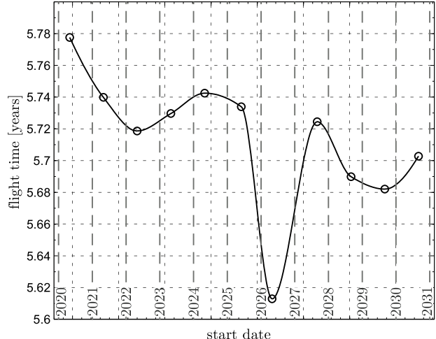
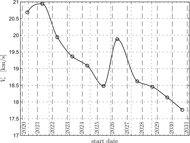
Figure 1 shows the traveltime from Earth to Uranus (starting from Earth C3=0) using an E-sail spacecraft with 0.9 mm/s2 characteristic acceleration. The characteristic acceleration is the maximum propulsive acceleration when the Sun-spacecraft distance is 1 au. An optimised low thrust orbit was computed using real planetary emphemerides and using the first day of each month as a starting date. Maximum usable thrust vector coning angle of 30o was assumed and the E-sail was turned off at 9 au. For each calendar year in 2020-2030, the minimum of the obtained 12 monthly trajectory traveltimes was calculated and plotted in Fig. 1. The corresponding Uranus-approaching hyperbolic excess speed is also plotted in Fig. 1. By we mean the relative speed of the probe with respect to Uranus, computed outside the planet’s gravity well but near the planet from the heliocentric perspective (within the framework of the patched conic approximation). As seen in Fig. 1, a typical value is km/s.
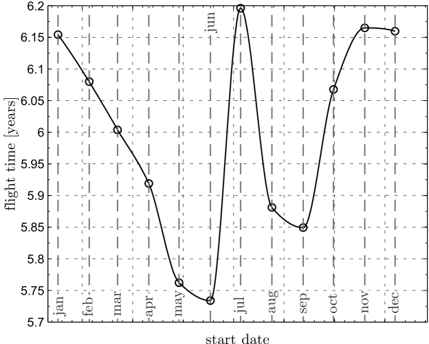
In Figure 2 we show the dependence of the traveltime on the starting month for an exemplary year of 2025. The difference in traveltime between the optimal month and the least favourable month is only 0.5 years. Figs. 1 and 2 show that in stark contrast to traditional mission architectures relying on gravity assist manoeuvres, with the E-sail the dependence of the traveltime on the starting date is feeble enough that one could in practice launch the probe at any time.
Figure 3 shows the atmospheric entry speed as a function of the hyperbolic excess speed . For the typical value of km/s the entry speed is km/s.
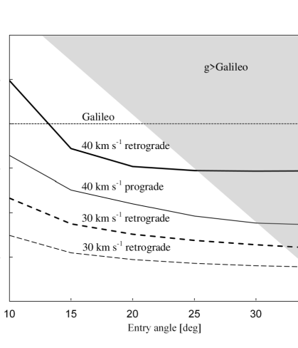
In Figure 4 we show the total heat load encountered by the probe as function of the entry angle and for various entry speeds . The entry speed is computed with respect to nonrotating planet; in Fig. 4 cases of maximum (equatorial) prograde and maximum retrograde entries are shown separately. For the typical km/s entry speed, the heat load remains by factor 3-4 below the Galileo value for all values of the entry angle. If the entry angle is steeper than 30∘-35∘, the maximum deceleration experienced by the probe goes beyond the Galileo value, however. Based on Fig. 4 we estimate that 30% heat shield mass fraction (Table 4) is conservative and leaves rather large freedom for the selection of the entry angle in the range 10∘-30∘.
3.1 Analysis of sensitivity of traveltime to mass
Figure 5 shows the dependence of the traveltime and Uranus atmosphere entry speed on the spacecraft characteristic acceleration. To simplify calculations, we assumed circular coplanar Earth and Uranus heliocentric orbits without ephemeris constraints in Fig. 5, while elsewhere in the paper we use full 3-D orbit calculations.
Let us consider an artificial case example where the wet mass of the carrier module is increased by 20%, from 150 kg to 180 kg. The total mass then increases from 556 kg to 586 kg (5.4 % increase). The characteristic acceleration gets decreased from 0.90 to 0.854 mm/s2, and from Fig. 5 one can infer that the traveltime increases by 7.5 %, or by 5 months. Also one sees from Fig. 5 that the entry speed is lowered by 4.7% from 21.2 to 20.2 km/s so that the dissipated energy is reduced by by 9%. This enables one to reduce the heat shield mass (originally 77 kg) by approximately a proportional amount (7 kg), thus cancelling 23 % of the originally assumed 30 kg mass increase.
4 Discussion and conclusions
We showed that given a working E-sail with currently projected performance characteristics [3], one could deliver an atmospheric probe mission to Uranus in less than six years. The mission would have Earth escape (C3=0) mass of 500-600 kg and the launch would be possible at any time without launch window constraints. Such mission could greatly contribute to the understanding of the history of the Solar System and especially possible giant planet migration.
Obviously, before these benefits can be realised, an E-sail based technology demonstration mission is needed which demonstrates deployment of long tethers, stability and manoeuvreability of the spinning tether rig and use of E-sail for primary propulsion. The cost of the demonstration mission would be much less than that of the proposed Uranus mission.
To probe the atmospheres of other giant planets and Titan, an analogous mission architecture could be used. One could implement such cluster mission by a fleet of identical probes designed for the worst case heat load (Saturn, unless Jupiter is also included) and the coldest cruise-phase thermal environment (Neptune). Alternatively, one could optimise each probe to its specific mission, with some saving in total mass and some increase in design cost.
5 Acknowledgement
The Electric Sail work is partly supported by the European Union FP7/2010 grant 262733, the Academy of Finland (grant 250591) and the Magnus Ehrnrooth Foundation.
References
- Janhunen [2004] P. Janhunen, Electric sail for spacecraft propulsion, J. Propulsion Power, 20, 4 (2004) 763–764.
- Janhunen et al. [2010] P. Janhunen et al., Electric solar wind sail: towards test missions, Rev. Sci. Instrum., 81, 111301, 2010.
- Janhunen et al. [2013] P. Janhunen, A.A. Quarta and G. Mengali, Electric Electric solar wind sail mass budget model, Geosci. Instrum. Method. Data Syst., 2, 85-95, 2013.
- Mengali et al. [2008] G. Mengali, A.A. Quarta and P. Janhunen, Electric sail performance analysis, J. Spacecr. Rockets, 45, 122–129, 2008.
- Quarta and Mengali [2010] A.A. Quarta and G. Mengali, Electric sail missions to potentially hazardous asteroids, Acta Astronaut., 66, 1506–1519, 2010.
- Quarta et al. [2012] A.A. Quarta, G. Mengali and P. Janhunen, Electric sail for near-Earth asteroid sample return mission: case 1998 KY26, J. Aerospace Eng., in press, 2013.
- Merikallio and Janhunen [2010] S. Merikallio and P. Janhunen, Moving an asteorid with electric solar wind sail, Astrophys. Space Sci. Trans., 6, 41–48, 2010.
- Mengali and Quarta [2009] G. Mengali and A.A. Quarta, Non-Keplerian orbits for electric sails, Cel. Mech. Dyn. Astron., 105, 179–195, 2009.
- Quarta and Mengali [2010] A.A. Quarta and G. Mengali, Electric sail mission analysis for outer Solar System exploration, J. Guid. Contr. Dyn., 33, 740–755, 2010.
- Quarta et al. [2011] A.A. Quarta, G. Mengali and P. Janhunen, Optimal interplanetary rendezvous combining electric sail and high thrust propulsion system, Acta Astronaut., 68, 603–621, 2011.
- Spilker et al. [2009] T.R. Spilker, D.H. Atkinson, S.K. Atreya, A. Colaprete, J.N. Cuzzi, L.J. Spilker, A. Coustenis, E. Venkatapathy, K. Reh and R. Frampton, Entry probe missions to the giant planets, American Geophysical Union, Fall meeting 2009, abstract P43A-1429, 2009.
- Tsiganis et al. [2005] K. Tsiganis, R. Gomes, A. Morbidelli and H.F. Levison, Origin of the orbital architecture of the giant planets of the Solar System, Nature, 435, 459–461, 2005.
- Levison et al. [2011] H.F. Levison, A. Morbidelli, K. Tsiganis, D. Nesvorny and R. Gomes, Late orbital instabilities in the outer planets induced by interaction with a self-gravitating planetesimal disk, Astronom. J., 142, 152 (11 pp), 2011.
- Tauber et al. [1994] M. Tauber, P. Wercinski, W. Henline and J. Paterson, Uranus and Neptune atmospheric entry probe study, J. Spacecr. Rockets, 31, 799–805, 1994.
- Rebuffat et al. [2011] D. Rebuffat, P. Falkner, J. Larranaga, J. Romstedt and K. Geelen, Study of planetary entry probes (PEP) for Venus and outer planets: Saturn, Uranus and Neptune, 8th International Planetary Probe Workshop, June 6-10, Portsmouth, VA, USA, 2011, abstract available at http://www.planetaryprobe.org/portals/0/DynamicForms_Uploads/a106.pdf.
- Johnson et al. [1992] T.V. Johnson, C.M. Yeates and R. Young, Space Science Reviews volume on Galileo mission overview, Space Sci. Rev., 60, 3–21, 1992.
- Seppänen et al. [2013] Seppänen, H., T. Rauhala, S. Kiprich, J. Ukkonen, M. Simonsson, R. Kurppa, P. Janhunen and E. Haeggström, One kilometer (1 km) electric solar wind sail tether produced automatically, Rev. Sci. Instrum., 84, 095102, 2013.
- Toivanen and Janhunen [2009] P.K. Toivanen and P. Janhunen, Electric sailing under observed solar wind conditions, Astrophys. Space Sci. Trans., 5, 61–69, 2009.
- Piszczor et al. [2008] Piszczor, M.F., S.W. Benson, D.A. Scheiman, H.J. Fincannon, S.R. Oleson and G.A. Landis, Advanced solar cell and array technology for NASA deep space missions, Photovoltaic Specialists Conference, San Diego, 11–16 May, 2008, doi:10.1109/PVSC.2008.4922856.
- Anflo and Möllerberg [2009] K. Anflo and R. Möllerberg, Flight demonstration of new thruster and green propellant technology on the PRISMA satellite, Acta Astronaut., 65, 1238–1249, 2009.