Hybrid paramagnetic-ferromagnetic
quantum computer design based on
electron spin arrays and a ferromagnetic nanostripe
Abstract
Designing an assembly of quantum nano-objects which can interact between themselves and be manipulated by external fields, while staying isolated from their noisy environment is the key for the development of future quantum technologies, such as quantum computers and sensors. Electron spins placed in a magnetic field gradient, interacting by dipolar magnetic couplings and manipulated by microwave pulses represent a possible architecture for a quantum computer. Here, a general design for the practical implementation of such nanodevice is presented and illustrated on the example of electron spins in silicon carbide placed nearby a permalloy ferromagnetic nanostripe. Firstly, the confined spin wave resonance spectrum of the nanostripe and the properties of its magnetic field gradient are calculated. Then, one shows how to avoid microwave driven electron spin decoherence. Finally, one shows that decoherence due to ferromagnetic fluctuations is negligible below room temperature for spins placed far enough from the nanostripe.
keywords:
QUANTUM COMPUTING,ELECTRON PARAMAGNETIC RESONANCE (EPR),SPIN WAVE RESONANCE(SWR),ELECTRON SPIN,MAGNETIC FIELD GRADIENT,FERROMAGNETIC STRIPE, SPIN DECOHERENCE, FERROMAGNETIC FLUCTUATIONSStrasbourg University]
Institut de Chimie de Strasbourg, Strasbourg University, UMR 7177 (CNRS-UDS),
4 rue Blaise Pascal, CS 90032, F-67081 Strasbourg Cedex,
France
\abbreviationsEPR (Electron Paramagnetic Resonance)
1 Introduction
During last decades, the development of nanotechnologies has allowed the experimental demonstration of entanglement between the quantum states of different pairs of nanosystems 1, 2, 4, 3, a key preliminary step towards quantum information processing. However, up scaling those experiments to at least ten coupled quantum systems, called quantum bits or qubits, on a single chip remains extremely challenging. This difficulty is linked to the need to couple quantum bits over nanoscale distances to perform conditional logical operations, except when some alternative strategy for long distance entanglement is available 6, 5. In the context of quantum bits encoded on electron spins in solids, the easiest solution to couple them is to use the dipolar magnetic coupling 7, 4, 3, which has however two drawbacks. Firstly, it becomes too weak beyond ten nanometers for efficient quantum states entanglement. Secondly, it is a permanent coupling, which requires methods to effectively switch on/off those couplings. The up scaling problem is thus directly related in this context to the difficulty to precisely position the electron spins on the chip and also to manipulate them with nanoscale resolution. State of art nanolithography and ion implantation methods used to build silicon 8 or diamond 9, 4, 3 based small scale quantum devices with few coupled electron spins are still far from reaching the ten qubits scale. Building solid state arrays of dipolar coupled electron spin qubits thus requieres an alternative nanotechnology and also a method and a nanodevice allowing to switch on/off those dipolar couplings. Transmission Electron Microscope (TEM) based nanofabrication methods with nanometer scale precision were recently demonstrated with carbon nanotubes 10 and graphene materials 11, and could provide the required alternative nanotechnology. Also, few years ago, it was shown that selective on/off switching of the dipolar coupling is possible using sequences of microwave pulses applied to dipolar coupled electron spins submitted to a magnetic field gradient 7. The problem was thus shifted to the production of strong magnetic field gradient. In the field of quantum computing with nuclear spins, it was proposed to use dysprosium nanoferromagnet to produce a huge magnetic field gradient 12. However, in the context of electron spin qubits, the nanoferromagnet also produces unwanted additional decoherence of the electron spins 13 due either to incoherent thermal excitation or to coherent microwave excitation of the spin waves 14 confined in the nanoferromagnet 15, 16.
Here I present a quantum register design containing a permalloy ferromagnetic nanostripe and nearby arrays of electron spins in silicon carbide (SiC). The spin qubits are silicon vacancies 17, 18, 20, 21, 23 that could be created in SiC using TEM nanofabrication methods 10, 11, 22, 18, 23. Using magnetostatic theory 12, the Landau Lifschitz equation of motion of magnetization in the nanoferromagnet 16, a one dimensional Schrodinger equation solved numerically by a transfer matrix method 24, and the density matrix theory of spin qubit decoherence 13, I show how to design simultaneously the magnetic field gradient and the confined spin waves spectrum of the nanoferromagnet in order to avoid additional decoherence. The designed quantum register could be operated with microwave pulses 38 and read out with high sensitivity using ensemble optical measurements of the paramagnetic resonance of silicon vacancy electron spins in SiC 17, 18.
2 Design and fabrication of a nanodevice with electron spin arrays nearby a ferromagnetic nanostripe
The general design proposed here for quantum information processing could be applied, in principle, to all kind of electron spin qubits like phosphorous donors in silicon 8, 34, nitrogen donors or NV centers in diamonds 9, 4, 3, transition metals ions or shallow donors in Zinc Oxide 25, 13, 26, 27, 28, N@C60 molecules 29, paramagnetic defects in graphene 33, paramagnetic dangling bonds arrays on hydrogen passivated silicon surface 31, or supramolecular assemblies of paramagnetic molecules such as neutral radical molecules 30 or copper phtalocyanine molecules 32, as long as regular dense arrays of them could be produced at precise positions nearby a ferromagnetic nanostripe. Without loss of generality and to be more quantitative, I focus here on a nanodevice made with silicon carbide and permalloy materials and build with top-down methods. The successive steps of two possible nanofabrication processes allowing to build such a nanodevice are described on figure 1a and 1b. The resulting nanodevice is shown on figure 1c.
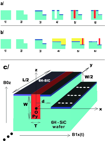
Each of the three SiC polytypes, 4H, 6H, and 3C, has some paramagnetic defects related to silicon vacancies which could potentially encode a good electron spin quantum bit 17, 18, 20, 21, 23. Some silicon vacancies defects in 6H-SiC has a spin S=3/2 with an isotropic g factor and a small zero field splitting 18. Their spin state can also be prepared by optical alignment 18 and it can be readout by the highly sensitive ODMR method (optically detected magnetic resonance) 19. It seems thus highly relevant to encode an electron spin qubit on this kind of silicon vacancy defect in 6H-SiC (for example at X band or at higher microwave frequency, using: and ). In the following calculations, one simplifies the spin qubit model by using a simple pseudo spin s=1/2 with a g factor g=2, without any loss of generality.
3 Dipolar magnetic field gradient outside the nanoferromagnet and effective Ising coupling between electron spin qubits
The practical implementation of single and two qubits quantum gates on chains of dipolar coupled electron spin qubits, as those shown on figure 1, requires appropriate microwave pulse sequences and a strong magnetic field gradient along the direction of the spin chains of the nanodevice to transform their dipolar coupling into an effective Ising like coupling 7. As here I also consider the possibility to perform ensemble measurements of the spin states of the spin qubits, for example using the highly sensitive ODMR method 19, the magnetic field gradient produced by the permalloy ferromagnetic stripe shown on figure 1 has not only to be strong enough along x, but also to be enough homogeneous along y and z. Strong enough along x means here that the energy difference between one qubit j (at position ) and the next one j+1 (at position ) along the spin chain has to be much larger than the energy associated to the dipolar coupling between them, which depends on their relative distance . In the nanodevice described on figure 1, is thus also the periodicity of each spin chain. The condition for an effective Ising coupling translates into , or approximately, , where is the value of the z component of the dipolar magnetic field produced by the ferromagnetic nanostripe at position x, assuming that for each spin qubit, and that the y coordinate of each spin qubit does not matter for the value of applied to the qubit. The irrelevance of the y coordinate is due to the approximate invariance by translation of the gradient produced by the long ferromagnetic nanostripe (infinite stripe model). This approximation is valid as long as the spin chains are created far from the edges of the ferromagnetic stripe along the y direction. Assuming a permalloy ferromagnetic stripe with a length along the y axis, a width along the x axis, and a depth along the z axis, further assuming that the ferromagnetic stripe is fully magnetized along the z axis by the static applied magnetic field , one can calculate using magnetostatic theory 12 the properties of the dipolar magnetic field produced by this nanoferromagnet, as shown on figure 2.
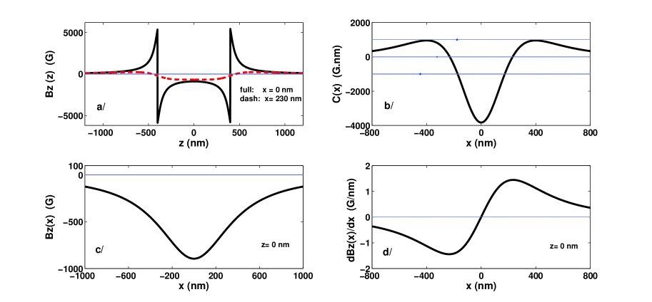
Figure 2 shows that as long as the spin qubits encoded onto silicon vacancies in SiC are created far from the edges of the ferromagnetic stripe along the y direction and close enough to the z=0 plane, then the relevant z component of the dipolar magnetic field produced by the ferromagnetic nanostripe can be considered as only dependent on x, and thus its gradient can also be approximately considered as being one dimensional along x. One finds here and . From those results, one can thus estimate whether the condition given above to obtain an effective Ising coupling between the spin qubits is satisfied. Assuming that most of the spin qubits are created in SiC by TEM at x positions close to and z=0, and further assuming a distance between successive spin qubits along the x direction, one finds that is more than hundred times larger than the dipolar coupling energy . One could thus, at first sight, conclude that the proposed nanodevice described on figure 1, satisfies the requirements for the practical implementation of quantum information processing with dipolar coupled electron spin qubits manipulated by appropriate sequences of microwave pulses 7. However, in order to avoid microwave driven decoherence, it is thus absolutely necessary to design the ferromagnetic nanostripe such that no spectral overlap between the precession frequencies of the spin qubits and the precession frequencies of the spin waves confined inside the ferromagnetic nanostripe 14, 15, 16 occurs.
4 Designing the field sweep confined spin wave resonance spectrum to avoid coherently driven electron spin qubit decoherence
One assumes here that the permalloy ferromagnetic nanostripe is almost fully magnetized at equilibrium along z at sufficiently low temperature and sufficiently high magnetic field (see figure 1). The excitation of a ferromagnetic spin wave implies that the magnetization inside the ferromagnetic nanostripe is no more uniform. In other words that means that the dipolar magnetic field acting on the nearby electron spin qubits outside the nanoferromagnet will become fluctuating, leading to spin qubit decoherence 13, 38. As it can be seen on figure 2a (in the case x=0) and on figure 3a, all the spins contained inside the ferromagnetic nanostripe produce a very inhomogeneous dipolar magnetic field inside the ferromagnetic nanostripe itself.
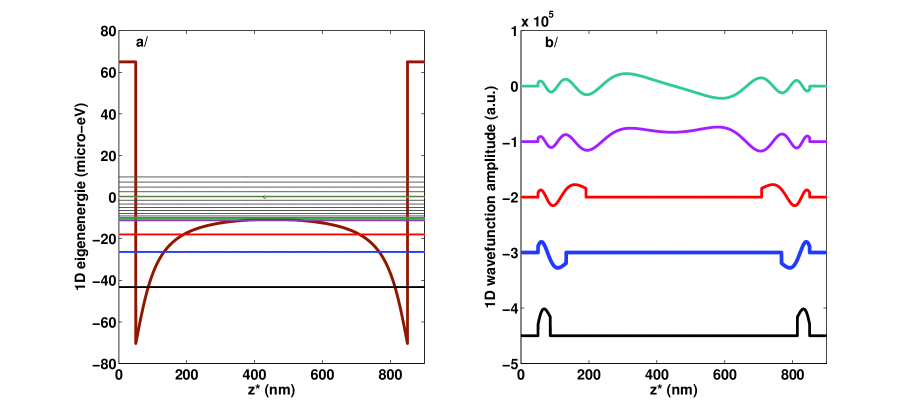
This leads to the confinement of the ferromagnetic spin waves 15 along the z axis, mainly on the edges of the ferromagnetic nanostripe. Here I have developed a method to calculate the confined spin wave resonance spectrum of a long ferromagnetic nanostripe fully magnetized. First, the Landau Lifschitz equation of motion of magnetization in the nanoferromagnet 16 is linearized. Then, the one dimensional eigenenergies and eigenfunctions of the spin waves confined in the inhomogeneous effective potential existing inside the ferromagnetic nanostripe along z are calculated, as it is shown respectively on figure 3a and figure 3b, using an effective Schrodinger equation solved numerically by a transfer matrix method 24. Then, the three dimensional eigenenergies of the confined spin waves are determined, and finally the resonance fields at which the microwave magnetic field of fixed frequency can excite a confined spin wave are determined, simply by writing the energy conservation rule. This rule says that the energy of the microwave photon absorbed should be equal to the three dimensional eigenenergie of the confined spin wave excited. It is important to note that the combination of the theoretical and of the experimental field sweep microwave absorption spectrum, provides an indirect method to determine the dipolar magnetic field produced by the ferromagnetic nanostripe on the spin qubits, because it is the same magnetization distribution that produces the dipolar magnetic field inside and outside the nanostripe. The full field sweep spectrum expected for the nanodevice described on figure 1 is plotted on figure 4a.
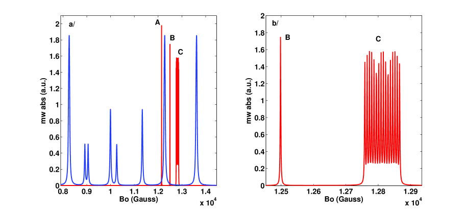
It includes the field sweep spectrum expected for the ferromagnetic nanostripe (blue resonance lines with resonance magnetic fields occurring between 0.80 and 1.40 Tesla). It also includes the field sweep spectrum expected for 16 electron spin qubits created at positions x close to , with x values comprised between and (ensemble C of 16 red resonance lines with resonance magnetic fields occurring around 1.28 Tesla). In order to see more clearly that those electron spin qubits resonance lines (C) are shifted towards high magnetic field values by the dipolar magnetic field produced by the ferromagnetic nanostripe and previously calculated, I also added on figure 4a the field sweep spectrum expected for an electron spin qubit created at infinite distance from the ferromagnetic stripe along the x axis (single A red resonance line with resonance magnetic field occurring around 1.215 Tesla) and also the field sweep spectrum expected for an electron spin qubit created at distance from the ferromagnetic stripe (single B red resonance line with resonance magnetic field occurring around 1.250 Tesla). The most important result shown on figure 4a and highlighted by figure 4b, is the possibility to design the electron spin based quantum register proposed here such that no spectral overlap occur between the 16 resonances lines of the shifted electron spin qubits and the resonance lines of the two confined spin waves of the ferromagnetic nanostripe occurring at the highest magnetic field values, the so called edge spin wave modes, occurring here at Q band, at 1.227 Tesla and at 1.362 Tesla. This provides a magnetic field interval of 1350 G free of any spin wave resonance. Further assuming an inhomogeneous linewidth below 1 G for each silicon vacancy electron spin qubit in nuclear spin free isotopically purified SiC, one could hope to build identical parallel arrays of 675 electron spin qubits along the x axis. However, state of art pulse EPR spectrometers operating at Q band have a resonator bandwidth of around 1 GHz, corresponding here to a magnetic field interval of around 350 G, in which only around 175 electron spin qubits could be manipulated using selective microwave pulses 38. It seems thus possible in principle to build a model quantum register of this kind having tens of electrons spins qubits with paramagnetic resonance lines not overlapping the confined spin wave resonance lines, thus avoiding any coherently driven spin decoherence.
5 Investigation of the spin qubit decoherence process due to incoherent magnetic fluctuations of the nearby nanoferromagnet
Till now, I have not considered the fact that the incoherent thermal excitation of ferromagnetic spin waves can produce some time dependent fluctuating dipolar magnetic field outside the ferromagnetic nanostripe, at the positions where the electron spin qubits are created. Those fluctuations always exist in a ferromagnetic nanostripe at equilibrium at a non zero temperature T. As it is also known from the standard density matrix theory of electron spin decoherence 13, any fluctuating magnetic field lead to electron spin decoherence. Thus here, one expects that the fluctuating dipolar magnetic field acting on electron spin qubits will produce a new spin decoherence process, which must be added to the other electron spin decoherence processes, which are intrinsic to the silicon vacancies in the silicon carbide matrix alone. The analysis of this new decoherence process requires the knowledge of the quantum correlation functions of this time dependent fluctuating dipolar magnetic field outside the ferromagnetic nanostripe 13. This is a complicated problem not addressed to date.
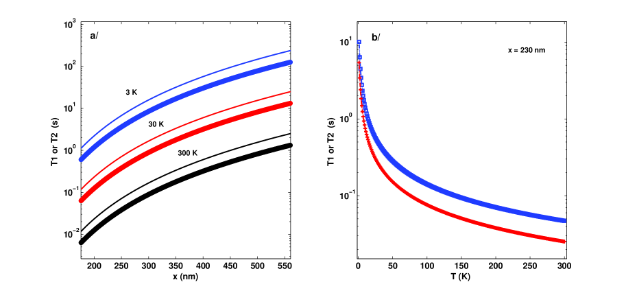
Here I present the results of a theoretical study of this problem based on the formalisms of the second quantization of spin waves and of the density matrix (details will be published elsewhere). The theory developed shows that this new electron spin decoherence process depends mainly, on the saturation magnetization of the nanoferromagnet, on the temperature, on the spectral detuning between the paramagnetic resonance of the electron spin qubit and the ferromagnetic resonance of the nanostripe, and also on the distance x of the qubit to the ferromagnetic nanostripe, as long as the qubit has a position assumed far from the edges of the ferromagnetic nanostripe along the y and z axis (y¡¡L, z¡¡W and x¿T/2). Results of the calculation of the electron spin coherence time and of the electron spin longitudinal relaxation time of an electron spin qubit of the nanodevice shown on figure 1 and operated at microwave Q band are presented on figure 5. At helium temperature, at microwave Q band, and with an applied magnetic field of around 1.28 Tesla, one finds: and . In those experimental conditions, this new decoherence process for the electron spin qubits should thus be negligible compared to other decoherence processes intrinsic to natural SiC. However, it could also become the dominant decoherence process for electron spin qubits embedded in a nuclear spin free isotopically purified SiC matrix, assuming intrinsic spin coherence time in SiC similar to those found in Si, in the range of few seconds 34. This suggest that quantum information processing with tens of electrons spins qubits encoded onto silicon vacancies in SiC, coherently manipulated by microwave pulse and submitted to the strong dipolar magnetic field gradient of the permalloy ferromagnetic nanostripe should be possible, at least at cryogenic temperatures. Also, at room temperature one finds and . Thus, those theoretical estimates, combined with the recent observation of room temperature spin coherence of some silicon vacancies in SiC over 18, suggest that a SiC-Permalloy quantum register such as the one designed here should keep its quantum coherence properties at room temperature at a sufficiently high level to perform fundamental studies of quantum entanglement over tens of dipolar coupled electrons spins qubits of silicon vacancies at room temperature.
6 Discussion
SiC is a very attractive material for the practical implementation with a top-down approach of the general quantum register design proposed here, firstly due to the long intrinsic electron spin coherence time of its paramagnetic defects 18 similar to the one in silicon 34, secondly due to the possibility to create silicon vacancies arrays in SiC using advanced TEM methods, and thirdly due to the possibilities for optical initialization and optical readout of the spin state of some silicon vacancies in SiC 17, 18. Note that a dysprosium ferromagnetic nanostripe would produce a three times bigger magnetic field gradient than in the case of permalloy. However, one expects with dysprosium an electron spin decoherence rate at least one order of magnitude larger than in the case of permalloy at cryogenic temperature due to its three times larger saturation magnetization and its much larger ferromagnetic resonance linewidth. In addition, Dysprosium is no more ferromagnetic at room temperature, contrary to permalloy, which suppresses any possibility for room temperature quantum information processing. Thus the hybrid paramagnetic-ferromagnetic nanodevice presented here, based on the SiC material widely used for high temperature electronics and on the permalloy material widely used for magnetic elements in computers , seems to be an excellent choice for quantum information processing with dipolar coupled electron spins selectively and coherently manipulated by resonant microwave pulses.
References
- 1 R. Blatt et al., Nature 453, 1008 (2008).
- 2 M. Neeley et al., Nature 467, 570 (2010).
- 3 F. Dolde et al., Nature physics 9, 139 (2013).
- 4 H. Bernien et al., Nature physics 6, 249 (2010).
- 5 H. Bernien et al., Nature 497, 86 (2013).
- 6 G. Burkard et al., Phys. Rev. B 74, 041307R (2006).
- 7 R. de Sousa et al., Phys. Rev. A 70, 52304 (2004).
- 8 R. Vrijen et al., Phys. Rev. A 62, 012306 (2000).
- 9 D.M. Toyli et al., Nano Lett. 10, 3168 (2010).
- 10 J.A. Rodriguez-Manzo et al., Nano Lett. 9, 2285 (2009).
- 11 A.W. Robertson et al., Nano Lett. 13, 1468 (2013).
- 12 J.R. Goldman et al., Appl. Phys. A 71, 11 (2000).
- 13 J. Tribollet, Eur. Phys. J. B 72, 531 (2009).
- 14 C. Kittel, Phys. Rev. 110, 1295 (1958).
- 15 J. Jorzick et al., Phys. Rev. Lett. 88, 47204 (2002).
- 16 I. Lee et al., Nature 466, 845 (2010).
- 17 A.L. Falk et al., Nature Communications 4, 1819 (2013).
- 18 D. Riedel et al., Phys. Rev. Lett. 108, 226402 (2012).
- 19 H. Kraus et al., Nature Physics 2826, 1 (2013).
- 20 H. Itoh et al., IEEE Transactions on Nuclear Science 37, 1732 (1997).
- 21 T. Wimbauer et al., Phys. Rev. B 56, 7384 (1997).
- 22 J.W. Steeds et al., Diamond Relat. Mater. 11, 1923 (2002).
- 23 J. Lefevre et al., J. of Appl. Phys. 105, 23520 (2009).
- 24 C. Jirauschek, IEEE J. of Quantum Electronics 45, 1059 (2009).
- 25 J. Tribollet et al., Europhysics Letters 84, 20009 (2008).
- 26 S.T. Ochsenbein et al., Nature Nanotechnology 6, 112 (2011).
- 27 R.E. George et al., Phys. Rev. Lett. 110, 27601 (2013).
- 28 K. Benzid et al., Europhysics Letters 104, 47005 (2013).
- 29 W. Harneit, Phys. Rev. A 65, 32322 (2002).
- 30 A. Tamulis et al., Chem. Phys. Lett. 436, 144 (2007).
- 31 S.R. Schofield et al., Nature Communications 4, 1649, 1 (2013).
- 32 M. Warner et al., Nature 503, 504 (2013).
- 33 R.R. Nair et al., Nature physics 8, 199 (2012).
- 34 A.M. Tyryshkin et al., Nature materials 11, 143 (2012).
- 35 R. Menzel et al., Appl. Surf. Science 136, 1 (1998).
- 36 A. Cheryl, Electronic Design 47, 38 (1999).
- 37 X. Yang et al., J. Vac. Sci. Technol. B 21, 3017 (2003).
- 38 A. Schweiger and G. Jeschke, Principles of pulse electron paramagnetic resonance (Oxford University Press, Oxford, UK ; New York, 2001).
7 Competing financial interests
The author declare that he has no competing financial interests.