Closed-circuit domain quadruplets in BaTiO3 nanorods embedded in SrTiO3 film
Abstract
Cylindrical BaTiO3 nanorods embedded in -oriented SrTiO3 epitaxial film in a brush-like configuration are investigated in the framework of the Ginzburg-Landau-Devonshire model. It is shown that strain compatibility at BaTiO3/SrTiO3 interfaces keeps BaTiO3 nanorods in the rhombohedral phase even at room temperature. Depolarization field at the BaTiO3/SrTiO3 interfaces is reduced by an emission of the 109-degree or 71-degree domain boundaries. In case of 10-80 nm diameter nanorods, the ferroelectric domains are found to form a quadruplet with a robust flux-closure arrangement of the in-plane components of the spontaneous polarization. The out-of-plane components of the polarization are either balanced or oriented up or down along the nanorod axis. Switching of the out-of-plane polarization with coercive field of about V/m occurs as a collapse of a 71-degree cylindrical domain boundary formed at the curved circumference surface of the nanorod. The remnant domain quadruplet configuration is chiral, with the macroscopic symmetry. More complex stable domain configurations with coexisting clockwise and anticlockwise quadruplets contain interesting arrangement of strongly curved 71-degree boundaries.
pacs:
77.80.-e,77.80.Dj,77.84.-sFerroelectric objects with nanoscale dimensions, such as nanodots, nanorods, nanotubes and nanolayers, both free-standing and embedded in thin films and bulk composites, are generally believed to provide a range of very attractive physical properties.Scott06Rev ; Lee ; Cata13 ; Slutsker2008 Recent progress in this field is remarkable – free-standing single crystal ferroelectric nanorods have been prepared from a number of classical ferroelectric materialsMao ; Urban ; Yun2002 ; Saeterli2010 ; Vasc05A ; Luo2003 ; Wang12B ; Spanier2006 and their properties measured,Suya04D ; Wang08F ; Yama10H ; Spanier2006 ; ZWang growing of planar ferroelectric superlattices has become a well established approach for material property design through the epitaxial strain,Schlom ; Waru ; Lee05 ; Slutsker2006 self-assembled 1-3 ferroelectric-paralectric nanocomposites were used to tailor the dielectric tunabilityYamada2009 and the ultrafast switching demonstrated for nanoscale capacitors already opens new perspectives for practical devices.Scott06Rev ; Li ; Gruverman2008A ; Gruverman2008 ; Gruverman2009 ; Jung ; Fridkin ; Kim Properties of all these ferroelectric nanoelements are strongly sensitive to the conditions of their surface.Slutsker2008 ; Wang2011 Uncompensated polarization charges at the surface perpendicular to the spontaneous polarization can lead to a strong modification of the ferroelectric state or even completely suppress the ferroelectricity,Ondr13 and even more complex behavior can be expected in composite nanostructures due to the epitaxial strains at the material interfaces.
Moreover, the established scaling laws for domain sizes suggest that ferroelectric nanoelements may host fairly small ferroelectric domains, that in turn can play a decisive role in determining their properties.Schilling2006 ; Schilling2009 In particular, numerous previous theoretical simulations have reported various closed-circuit domain configurations and vortices in electrically isolated ferroelectric nanodots and nanorods.Fu ; Naumov ; Stachiotti ; Baudry ; Baudry2012 ; Chen2012 ; Laho08 Interestingly, the straightforward experimental evidence for these very interesting natural topological defects is so far very limited and quite often, an alternative star-like ”quadrant-quadrupole” arrangementSchilling ; Gregg was observed in tetragonal ferroelectrics instead of the ”flux-closure” curling polarization state.Schilling ; Boro13 ; Ahlu13 ; McQuaid ; Gregg ; Chang ; Ivry ; McGilly2010 Considerations about possible ways to realize such curling polarization states have led us to theoretical investigations of the behavior of a model system consisting of ferroelectric BaTiO3 nanorods embedded in a matrix of a thin dielectric film of insulating SrTiO3. The aim of this paper is to report the condition of formation of these peculiar closed-circuit domain configurations in this system.
Phase-field simulations presented in this article are based on the phenomenological Ginzburg-Landau-Devonshire (GLD) model my ; Hlin09 ; Mart10 in which the excess Gibbs free-energy functional is expressed in terms of ferroelectric polarization , its spatial derivatives and strain components , as
| (1) |
where the first term
| (2) |
stands for the room-temperature GLD functional, and stand for components of the elastic, electrostriction and gradient tensors, while and stands for the components of external electric field and the applied homogeneous stress tensor, respectively. The other term in Eq. (1) describes the electrostatic energyHuChen3D ; Khacha
| (3) |
associated with the interaction of individual dipoles with the field created by the inhomogeneous part of the polarization field
| (4) |
where , is the relative background permittivity of the medium (without the primary order parameter contribution) and is the permittivity of vacuum.
In order to find the equilibrated domain structure under specified conditions, we have applied the usual phase-field approach Nambu ; HuChen3D ; Artemev ; simul ; Slutsker2008 consisting in simulation of the natural ”equilibration” process by numerical solution of the corresponding time-dependent Ginzburg-Landau equation for the field of polarization
| (5) |
where is a kinetic coefficient controlling the energy dissipation rate of the system. Mechanical equilibrium is assumed to be achieved at each instant so that the inhomogeneous strain field can be eliminated from the energy functional of Eq. (1) using the corresponding Euler-Lagrange equations.Nambu ; Khacha ; simul ; Klot03 GLD model parameters for the room temperature BaTiO3 were selected same as in Refs. Hlin09, ; Ondr13, . For SrTiO3, we have used free-energy coefficients of Ref. Sheng, . The most essential difference at room temperature is obviously the positive value of the quadratic coefficient in SrTiO3. Since SrTiO3 and BaTiO3 are rather similar materials, the parameters defining the gradient, elastic, electrostrictive and dipole-dipole interactions of SrTiO3 were taken same as for BaTiO3.Yama72 Having in mind an epitaxial film clamped to a substrate with an effective lattice constant comparable to cubic BaTiO3, we have imposed the average in-plane strain components and out-of-plane stress components to zero (, ). To define a realistic time scales in the simulated processes, the kinetic coefficient was set to , in agreement with the earlier estimations timescale . The simulations were conducted under periodic boundary conditions within a 2D or 3D rectangular discrete arrays. The equation (5) was resolved numerically in Fourier space by a second-order semi-implicit method with spatial steps 0.5 nm and individual time steps 0.5 fs.
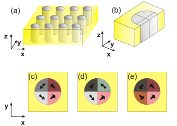
The investigated nanostructure is sketched in Fig. 1a. Since the nanorods are fully embedded into the SrTiO3 matrix, the epitaxial matching prevents the development of large electrostrictive distortion in the BaTiO3 nanorods, and, consequently, it strongly influences the competition between various ferroelectric states. Nanorods of 10-80 nm diameter studied in the present work were in the rhombohedral ferroelectric state, with local polarization close to the directions. To minimize the depolarization field, the polarization tends to be tangential to the BaTiO3/SrTiO3 interface. Stable configurations obtained for the 10-80 nm diameter nanorods typically break up in 4 domains, separated by 2 perpendicular planar domain boundaries intersecting on the axis of the rod (Fig. 1b). The adjacent domains are arranged in a head-to-tail manner, so that the in-plane polarization components are forming a clockwise or an anticlockwise closed-circuit configuration (see the actual results for 40 nm diameter rods shown in Fig. 1c,d,e). The sequence of the out-of-plane polarization components in the four quadrants of the nanorod depends on the initial conditions. Three basic cases were found: the up-up-down-down-type domain structure with 109- and 71-degree domain boundaries (Fig. 1c), the up-down-up-down-type domain structure with two 109-degree domain boundaries (Fig. 1d) and the domain structure with two 71-degree domain boundaries and uniform sense of the -component of the polarization (Fig. 1e). Note that the asymmetric domain structure in Fig. 1c contains a 71-degree boundary perpendicular to the -axis and a 109-degree boundary perpendicular to the to -axis, while there are only 109 degree boundaries in the ) domain structure shown in Fig. 1d.
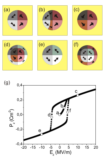
All these domain structures are stable with respect to a small external electric fields. Interestingly, the components can be reversed by the out-of-plane electric field of the order of 5 MV/m without destruction of the closed-circuit domain quadruplet arrangement of the in-plane polarization components. Different stages of the process of polarization reversal as calculated for a 20 nm diameter nanorod are depicted in Fig. 2. Poling of the nanorod in a virgin state starts by splitting of the 109-degree domain boundary into a pair of 71-degree domain boundaries, one fixed at the original position and the other one moving away (see Fig. 2b). The moving boundary is eventually fully forced out from the nanorod when the electric field reaches about 5 MV/m. In the final state, the out-of-plane components of the polarization are uniformly oriented so that the total is maximized (see Fig. 2c and Fig. 2g). This configuration remains stable up to about 1 GV/m as well as after the field removal. In case of initial state of Fig. 1d, the mobile 71-degree domain boundaries peal off from both 109-domain boundaries, but otherwise the poling process is very similar to that of Fig. 2.
The reversal of the previously poled state with the remnant polarization proceeds differently - it is realized by a collapse of a single quasi-cylindrical 71-degree domain boundary formed at the circumference surface of the nanorod (see Fig. 2d). This process occurs in a fairly narrow electric field range so that the quasistatic hysteresis loop has a well defined intrinsic coercive field of about 5 MV/m (see Fig. 2g). The overall remnant polarization of the nanorod (0.16 C/m2) is comparable to the spontaneous polarization of the bulk BaTiO3 (0.26 C/m2 in the present model). As expected, it decreases with temperature and vanishes near K, which is about 10 K below the cubic-tetragonal phase transition of stress-free bulk state (see Fig. 3). Interestingly, the speed of the polarization reversal is limited only by the nanorod radius and domain boundary mobility and so it could be extremely fast. As an extreme example, we have seen that within the present model and its very simple kinetics, 20 nm nanorod can be switched by 6 MV/m electric field within few ps.

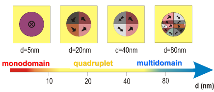
Let us stress that in the range of stability of the rhombohedral phase, the quadruplet states could be considered as the basic stable configuration for a broad range of diameters (about 10-80 nm). In our calculations the polarized domain quadruplet state is the true ground state for a 20 nm nanorod, the asymmetric state of Fig. 1c is the ground state for 25-70 nm nanorod and, at 80 nm, a multidomain configuration is already energetically more favorable than the quadruplet structure (see Fig. 4). The overall trend shown in Fig. 4 is probably quite generic even though the energy differences between symmetrically inequivalent quadruplets are very small and may not be experimentally relevant. Nevertheless, when any of these structures is poled to the quadruplet state of Fig. 1e, it remains stable. This is the essential property that does have a potential for practical devices. Obviously, a very thin nanorods eventually do not have domains at all; in fact, in present model the nanorods with diameter below about 10 nm show a tetragonal monodomain state (with the polarization oriented along the nanorod axis, see Fig. 4).
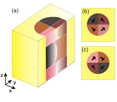
Finally, it is worth to note that the above discussed poled quadruplet state has a macroscopic symmetry, which is a chiral one. The in-plane clockwise or anticlockwise component of the polarization could be reversed by inhomogeneous fields. Therefore, the in-plane component could be also used to store information. Moreover, we have noticed that the ferroelectric nanorods can also sustain a more complex domain state with the coexisting clockwise or anticlockwise layers (see Fig. 5). In this case, the interim layer is formed by strongly bend 71-degree domain boundaries. The core of the curling polarization is also curved and it is terminated at the circumference surface of the nanorod. Vertical motion of this interim layer could facilitate the eventual switching between the clockwise or anticlockwise state. In either case, the interim layer is preserved during the switching of the out-of-plane polarization, and it does not have any noticeable influence on the -switching process – the coercive field is practically identical to that of the basic structure.
Interestingly, the 71-degree domain boundaries in all the above closed-circuit domain quadruplet structures have an unusual orientation, which does fulfill the condition of polarization charge compatibility but which does not satisfy the conventional condition of the bulk spontaneous strain compatibility Janovec . The same obviously also holds for the curved 71-degree domain boundaries shown in Fig. 2 and Fig. 5. Full discussion of this finding is beyond the scope of the present work but it is clear that it testifies a very specific softness of such boundaries and it is quite possible that this could be a typical and important property of 71-degree domain boundaries in other rhombohedral ferroelectric perovskites.
In summary, our phase-field simulations suggest that 1-3 type nanocomposites with ferroelectric nanorods enables to stabilize the interesting closed-circuit domain quadruplets. The rhombohedral closed-circuit domain quadruplets of the BaTiO3/SrTiO3 nanocomposite films described here are particularly stable because the monodomain tetragonal state of the nanorod is suppressed by mechanical clamping and the rhombohedral monodomain state of the nanorod is suppressed by the electrical boundary conditions on its circumference surface. Moreover, the out-of-plane polarization of these nanorods is facilitated by nonconventional 71-degree domain boundaries that can be easily bend and nucleated from residual 109-degree domain boundaries and at the nanorod circumference surfaces. We believe that these intriguing findings will be an inspiration for the continuation of nanoferroelectric studies.
Acknowledgements.
This work is supported by the Sciex-NMSch program of the Swiss Federal Government (Project code 11.117). Additional funding was received from the European Research Council under the EU 7th Framework Programme (FP7/2007-2013)/ERC grant agreement no (268058) Mobile-W and by Czech Science Foundation (Project GACR P204/11/1011).References
- (1) J. F. Scott, J. Phys.: Condens. Matter 18, R361 (2006).
- (2) W. Lee, H. Han, A. Lotnyk, M.A. Schubert, S. Senz, M. Alexe, D. Hesse, S. Baik, and U. Gösele, Nature Nanotechnology 3, 402 (2008).
- (3) J. Slutsker, A. Artemev, and A. Roytburd, Phys. Rev. Lett. 100, 087602 (2008).
- (4) G. Catalan, J. Seidel, R. Ramesh, and J. F. Scott, Rev. Mod. Phys. 84, 119 (2012).
- (5) Y. Mao, S. Banerjee, and S. S. Wong, J. Am. Chem. Soc. 125, 15718 (2003).
- (6) J. J. Urban, W. S. Yun, Q. Gu, and H. Park, J. Am. Chem. Soc. 124, 1186 (2002).
- (7) Y. Luo, I. Szafraniak, V. Nagarajan, R. B. Wehrspohn, M. Steinhart, J. H. Wendorff, N. D. Zakharov, R. Ramesh, and M. Alexe, Integrated Ferroelectrics 59, 1513 (2003).
- (8) W. S. Yun, J. J. Urban, Q. Gu and H. Park, Nano Lett. 2, 447 (2002).
- (9) R. Sæterli, P. M. Rørvik, C. C. You, R. Holmestad, T. Tybell, T. Grande, A. T. G. van Helvoort and M.-A. Einarsrud, J. Appl. Phys. 108, 124320 (2010).
- (10) E. Vasco, A. Magrez, L. Forró, and N. Setter, J. Phys. Chem. B 109, 14331 (2005).
- (11) J. Wang, A. Durussel, C. S. Sandu, M. G. Sahini, Z. He, and N. Setter, J. Crystal Growth 347, 1 (2012).
- (12) J. E. Spanier, A. M. Kolpak, J. J. Urban, I. Grinberg, L. Ouyang, W. S. Yun, A. M. Rappe, and H. Park, Nano Lett. 6, 735 (2006).
- (13) G. Suyal, E. Colla, R. Gysel, M. Cantoni, and N. Setter, Nano Lett. 4, 1339 (2004).
- (14) J. Wang, C. Stampfer, C. Roman, W. H. Ma, N. Setter, and C. Hierold, Appl. Phys. Lett. 93, 223101 (2008).
- (15) T. Yamada, J. Wang, O. Sakata, H. Tanaka, Y. Ehara, S. Yasui, N. Setter, and H. Funakubo, Jpn. J. Appl. Phys. 49, 09MC09 (2010).
- (16) Z. Wang, A. P. Suryavanshi, and M. F. Yu, Appl. Phys. Lett. 89, 082903 (2006).
- (17) D. G. Schlom, L.-Q. Chen, C.-B. Eom, K. M. Rabe, S. K. Streiffer, and J.-M. Triscone, Annu. Rev. Mater. Res. 37, 589 (2007).
- (18) M. P. Warusawithana, E. V. Colla, J. N. Eckstein, and M. B. Weissman, Phys. Rev. Lett. 90, 036802 (2003).
- (19) H. N. Lee, H. M. Christen, M. F. Chisholm, C. M. Rouleau, and D. H. Lowndes, Nature 433, 395 (2005).
- (20) J. Slutsker, I. Levin, J. Li, A. Artemev, and A. L. Roytburd, Phys. Rev. B 73, 184127 (2006).
- (21) T. Yamada, C. S. Sandu, M. Gureev, V. O. Sherman, A. Noeth, P. Muralt, A. K. Tagantsev, and N. Setter, Adv. Mater. 21, 1363 (2009).
- (22) J. Li, B. Nagaraj, H. Liang, W. Cao, C. H. Lee, and R. Ramesh, Appl. Phys. Lett. 84, 1174 (2004).
- (23) A. Gruverman, D. Wu and J. F. Scott, Phys. Rev. Lett. 100, 097601 (2008).
- (24) A. Gruverman, D. Wu, H.-J. Fan, I. Vrejoiu, M. Alexe, R. J. Harrison, and J. F. Scott, J. Phys.:Condens. Matter 20, 342201 (2008).
- (25) A. Gruverman, J. Mater. Sci. 44, 5182 (2009).
- (26) D. J. Jung, K. Kim, and J. F. Scott, J. Phys: Condens. Matter 17, 4843 (2005).
- (27) V. M. Fridkin, R. V. Gaynutdinov and S. Ducharme, Uspekhi Fizicheskikh Nauk 180 (2), 209 (2010).
- (28) Y. Kim, H. Han, W. Lee, S. Baik, D. Hesse, and M. Alexe, Nano Lett. 10, 1266 (2010).
- (29) J. J. Wang, E. A. Eliseev, X. Q. Ma, P. P. Wu, A. N. Morozovska, and L.-Q. Chen, Acta Materialia 59, 7189 (2011).
- (30) P. Ondrejkovic, P. Marton, M. Guennou, N. Setter, and J. Hlinka, Phys. Rev. B 88, 024114 (2013).
- (31) A. Schilling, T. B. Adams, R. M. Bowman, J. M. Gregg, G. Catalan, and J. F. Scott, Phys. Rev. B. 74, 024115 (2006).
- (32) A. Schilling, D. Byrne, G. Catalan, K. G. Webber, Y. A. Genenko, G. S. Wu, J. F. Scott, and J. M. Gregg, Nano Lett. 9, 3359 (2009).
- (33) H. Fu and L. Bellaiche, Phys. Rev. Lett. 91 257601 (2003).
- (34) I. I. Naumov, L. Bellaiche, and H. Fu, Nature 432, 737 (2004).
- (35) M. G. Stachiotti and M. Sepliarsky, Ferroelectrics 427, 41 (2012).
- (36) L. Baudry, I. A. Luk’yanchuk and A. Sené, Ferroelectrics 427, 34 (2012).
- (37) L. Baudry, I. A. Luk’yanchuk, and A. Sené, Integrated Ferroelectrics 133, 96 (2012).
- (38) W. J. Chen, Y. Zheng, and B. Wang, Appl. Phys. Lett. 100, 062901 (2012).
- (39) L. Lahoche, I. A. Luk’yanchuk, and G. Pascoli, Integrated Ferroelectrics 199, 60 (2008).
- (40) A. Schilling, S. Prosandeev, R. G. P. McQuaid, L. Bellaiche, J. F. Scott, and J. M. Gregg, Phys. Rev. B 84, 064110 (2011).
- (41) J. M. Gregg, Ferroelectrics 433, 74 (2012).
- (42) F. Borodavka, I. Gregora, A. Bartasyte, S. Margueron, V. Plausinaitiene, A. Abrutis, and J. Hlinka, J. Appl. Phys. 113, 187216 (2013).
- (43) R. Ahluwalia, N. Ng, A. Schilling, R. G. P. McQuaid, D. M. Evans, J. M. Gregg, D. J. Srolovitz, and J. F. Scott, Phys. Rev. Lett. 111, 165702 (2013).
- (44) R. G. P. McQuaid, L. J. McGilly, P. Sharma, A. Gruverman, and J. M. Gregg, Nature Communications 2, 404 (2011).
- (45) L.-W. Chang, V. Nagarajan, J. F. Scott and J. M. Gregg, Nano Lett. 13, 2553 (2013).
- (46) Y. Ivry, D. P. Chu, J. F. Scott, and C. Durkan, Phys. Rev. Lett. 104, 207602 (2010).
- (47) L. J. McGilly, A. Schilling, and J. M. Gregg, Nano Lett. 10, 4200 (2010).
- (48) J. Hlinka and P. Marton, Phys. Rev. B 74, 104104 (2006).
- (49) J. Hlinka, P. Ondrejkovic, and P. Marton, Nanotechnology 20, 105709 (2009).
- (50) P. Marton, I. Rychetsky, and J. Hlinka, Phys. Rev. B 81, 144125 (2010).
- (51) H.-L. Hu and L.-Q. Chen, J. Am. Ceram. Soc. 81, 492 (1998).
- (52) S. Semenovskaya and A. G. Khachaturyan, J. Appl. Phys. 83, 5125 (1998).
- (53) S. Nambu and D. A. Sagala, Phys. Rev. B 50, 5838 (1994).
- (54) A. Artemev, J. Slutsker, and A. L. Roytburd, IEEE Trans. Ultras. Ferr. Freq. Contr. 55, 963 (2008).
- (55) P. Marton and J. Hlinka, Phase Transitions 79, 467 (2006).
- (56) J. Hlinka and E. Klotins, J. Phys.: Condens. Matter 15, 5755 (2003).
- (57) G. Sheng, Y. L. Li, J. X. Zhang, S. Choudhury, Q. X. Jia, V. Gopalan, D. G. Schlom, Z. K. Liu, and L. Q. Chen, Appl. Phys. Lett. 96, 232902, (2010).
- (58) T. Yamada, J. Appl. Phys. 43 328 (1972).
- (59) J. Hlinka, Ferroelectrics 349, 49 (2007).
- (60) J. Fousek and V. Janovec, J. Appl. Phys. 40, 135 (1969).