Coexistence of Superconductivity and Ferromagnetism in P-doped EuFe2As2
Abstract
The magnetic structure of the Eu2+ moments in the superconducting EuFe2(As1-xPx)2 sample with x = 0.15 has been determined using element specific x-ray resonant magnetic scattering. Combining magnetic, thermodynamic and scattering measurements, we conclude that the long range ferromagnetic order of the Eu2+ moments aligned primarily along the c axis coexists with the bulk superconductivity at zero field. At an applied magnetic field T, superconductivity still coexists with the ferromagnetic Eu2+ moments which are polarized along the field direction. We propose a spontaneous vortex state for the coexistence of superconductivity and ferromagnetism in EuFe2(As0.85P0.15)2.
pacs:
74.70.Xa, 75.25.-j, 75.40.Cx, 74.25.DwI Introduction
The discovery of the iron-based superconductors Kamihara et al. (2008) a few years ago has stimulated tremendous research interests worldwide in unconventional high-T superconductivity Johnston (2010). Most of the research on the Fe-based superconductors has focused on mainly four systems, (1) the quaternary “1111” systems, RFeAsO1-xFx (R = La, Nd, Sm, or Pr, etc.) with T as high as 56 K Kamihara et al. (2008); Takahashi et al. (2008); Chen et al. (2008); Zhi-An et al. (2008), (2) the ternary “122” systems, AFe2As2 (A = Ba, Ca, Sr, or Eu etc) with T upto 38 K, Rotter et al. (2008); Jeevan et al. (2008); Sasmal et al. (2008), (3) the binary “11” system (e. g. FeSe) Hsu et al. (2008) with T ~ 18 K and (4) the ternary “245” systems, A2Fe4Se5 (A = K, Rb, Cs) with T ~ 30 K Guo et al. (2010). Superconductivity can be achieved in all the above compounds in different ways, for example, either by electron or hole doping in the Fe-As layers Leithe-Jasper et al. (2008); Sefat et al. (2008) or by isovalent substitution Schnelle et al. (2009); Wang et al. (2009); Jiang et al. (2009). Internal chemical pressure by isovalent substitution of arsenic with phosphorus Wang et al. (2009); Jiang et al. (2009) or external hydrostatic pressure can also give rise to superconductivity Miclea et al. (2009); Tokiwa et al. (2012).
EuFe2As2 is an interesting member of the “122” family since the A site is occupied by Eu2+, which is an S-state rare-earth ion possessing a 4f7 electronic configuration with the electron spin S = 7/2 Marchand and Jeitschko (1978). EuFe2As2 exhibits a spin density wave (SDW) transition in the Fe sublattice concomitant with a structural phase transition at 190 K. In addition, Eu2+ moments order in an A-type antiferromagnetic (AFM) structure at 19 K (ferromagnetic layers ordered antiferromagnetically along the c axis) Herrero-Martín et al. (2009); Xiao et al. (2009, 2010). Superconductivity can be achieved in this system by substituting Eu with K or Na (Refs. [Qi et al., 2008; Jeevan et al., 2008]), As with P (Ref. Ren et al., 2009), and upon application of external pressure (Refs. [Miclea et al., 2009; Terashima et al., 2009; Tokiwa et al., 2012]).
Superconductivity and magnetism are two antagonistic phenomena since the superconducting state expels external magnetic flux. Nevertheless, superconductivity in the pnictides and cuprates is always found in close proximity to an antiferromagnetic order and the superconducting pairing is believed to be mediated by the antiferromagntic spin fluctuations Johnston (2010). Most surprising is the coexistence of ferromagnetism and superconductivity as recently proposed by many groups for the P-doped EuFe2As2 samples Cao et al. (2011); Ahmed et al. (2010); Nowik et al. (2011); Zapf et al. (2011, 2013). Based on Mössbauer studies on superconducting polycrystalline samples, Nowik et al. Nowik et al. (2011) concluded that the Eu2+ moments are aligned ferromagnetically along the c axis with a possible tilting angle of 20∘ from the c axis. Zapf et al. also Zapf et al. (2011) concluded based on macroscopic measurements that the Eu2+moments in EuFe2(As1-xPx)2 order in a canted A-type antiferromagnetic structure with the spin component along the c direction being ferromagnetically aligned. The small in plane component of the Eu2+moments in the A-type AFM structure undergoes a spin glass transition where the moments between the layers are decoupled Zapf et al. (2013).
For a magnetic superconductor with rare-earth moments, several theoretical studies claim that the superconductivity can coexist with several forms of the magnetic states, namely, (a) “cryptoferromagnetism” (which is a ferromagnetic state with small domains, smaller than the superconducting coherence length) Anderson and Suhl (1959) or (b) transverse amplitude modulated collinear antiferromagnetic structure or (c) spiral antiferromagnetic structure or (d) with a spontaneous vortex state of the magnetic moments. A spontaneous vortex state or a self-induced vortex state is a new state of matter in which the two competing orders, superconductivity and ferromagnetism, coexist due to the lower free energy of the combined states compared to the individual ones Greenside et al. (1981). The Pure ferromagnetic state is least preferred. These results clearly show the importance of the alignment for the rare-earth moments in the superconducting samples.
To the best of our knowledge, for the superconducting EuFe2(As1-xPx)2 single crystal samples, direct microscopic evidence for the proposed ferromagnetic and/or antiferromagnetic structure is still lacking. Due to the strong neutron absorption of Eu together with the small sample mass of the P-doped single crystals, the magnetic structure determination in EuFe2(As1-xPx)2 via neutron diffraction is considerably more challenging than that of other members of the new superconductors. The only attempt was made on a powder sample of the non-superconducting EuFe2P2 where it was concluded that the Eu2+ moments order ferromagnetically with a canting angle of 17∘ from the c axis Ryan et al. (2011). Here we report on the first element-specific x-ray resonant magnetic scattering (XRMS) studies of the superconducting EuFe2(As1-xPx)2 to explore the details of the magnetic structure of the Eu2+ moments. Our resonant scattering experiments show that the Eu2+ moments order ferromagnetically along the c axis at zero field and undergo a transition into a field induced ferromagnetic state along the applied magnetic field direction for applied magnetic fields 0.6 T. Both the zero and applied magnetic field ferromagnetic order of the Eu2+ moments coexist with the bulk superconductivity.
II Experimental Details
Single crystals of EuFe2(As1-xPx)2 with and were grown using FeAs flux Jeevan et al. (2011). For the scattering measurements and for the superconducting composition , an as-grown right isosceles triangular shaped single crystal with a base of approximately 2 mm and a thickness of 0.1 mm was selected. The same crystal was used for all the macroscopic characterizations presented in this communication. For the non-superconducting sample, a crystal of approximate dimensions of 22 mm3 was chosen. The surface of both single crystals were perpendicular to the axis. The XRMS experiments were performed at the Eu L3-edge at beamline P09 at the PETRA III synchrotron at DESY Strempfer et al. (2013). The incident radiation was linearly polarized parallel (-polarization) and perpendicular (-polarization) to the horizontal and vertical scattering planes for the 15% and 5% doped samples, respectively. The spatial cross section of the beam was 0.2 (horizontal)0.05 (vertical) mm2. Copper Cu (2 2 0) was used at the Eu L3 absorption edge as a polarization and energy analyzer to suppress the charge and fluorescence background relative to the magnetic scattering signal. The sample was mounted at the end of the cold finger of a cryomagnet with [2 1 0]T-[0 0 1]T plane coincident with the scattering plane for the 15% doped sample. The magnetic field was applied along the [1 0] direction which is perpendicular to the scattering plane. The 5% doped sample was measured inside a closed cycle Displex cryogenic refrigerator with [1 1 0]T-[0 0 1]T as the scattering plane. Measurements at P09 were performed at temperatures between 5 and 180 K. For convenience, we will use tetragonal (T) notation unless otherwise specified.
III Experimental Results
III.1 Macroscopic Characterizations
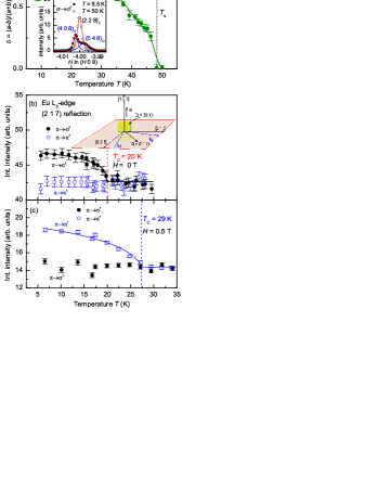
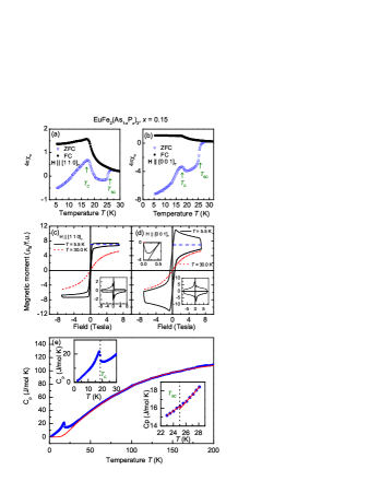
Figure 1 (a-b) and (c-d) show magnetic susceptibility (M-T) and isothermal magnetization (M-H) of the sample, respectively, measured for magnetic fields parallel and perpendicular to the c axis using a Quantum Design (SQUID) magnetometer. Zero field cooled magnetization becomes negative for both field directions at T = 25 K, signifying a superconducting transition at this temperature. Upon cooling towards the onset of Eu2+ ordering at T = 19 K, the superconducting signal is first weakened, before it becomes more pronounced at temperatures below T. Superconductivity wins over the Eu2+ magnetism if temperature is lowered further. The diamagnetic volume susceptibility for the magnetic field parallel to the [1 1 0] direction (in this direction demagnetization correction is small Osborn (1945)) is greater than -0.5 indicating bulk superconductivity 111 is larger than the ideal value of -1. However, considering the ferromagnetic contribution of the Eu2+ (as found by the scattering measurements), the effective volume susceptibility due to the superconductivity (SC), ( ) = , might be very close to -1. The observed ferromagnetic contribution for the non-superconducting ferromagnet EuFe2P2 Feng et al. (2010) (in ZFC data) is the same order of magnitude as the in the present case.. Effective diamagnetic susceptibility close to -1 for the ZFC curve provides an upper limit of superconducting volume fraction of 100%. Figures 1 (c) & (d) show hysteresis loops at T = 5 and 30 K for the two field directions. The observed hysteresis curves look different than a type II nonmagnetic superconductor. However, a jump in magnetization, which is typical for a type-II superconductor, is clearly observed at 7 T magnetic field between the field increasing and decreasing cycles. To understand the atypical hysteresis curve, we assume a ferromagnetic contribution of the Eu2+ moments at an applied magnetic field H (Tesla) by,
since very little hysteresis was observed for the ferromagnetic end member EuFe2P2 Feng et al. (2010). Lower insets to Fig. 1 (c) and (d) show magnetization after subtraction of the ferromagnetic contribution from the Eu2+ moments according to Eq. III.1. The hysteresis curves after subtraction look very similar to the other Fe based superconductors Prozorov et al. (2008); Sefat et al. (2008). The jump at 7 T magnetic field is consistent with Bean’s critical state model together with Lenz’s law Bean (1962); Kim et al. (1963); Fietz et al. (1964). Reversal of the direction of change of applied field as at 7 T does not remove the specimen from the critical state but merely reverses locally the direction of the critical current according to Lenz’s law. Therefore, magnetization measurements strongly hint towards a ferromagnetic superconductor in an applied magnetic field. The heat capacity of the same single crystal was measured using a Quantum Design physical property measurement system (PPMS) and is shown in Fig. 1(e). Specific heat data show a clear phase transition at T = 19 K indicating the onset of the Eu2+ magnetic order. A specific heat jump at T is clearly visible and amounts to C 350 mJ/mol.K which is slightly less but of the same order of magnitude as that observed for the K-doped BaFe2As2 system Ni et al. (2008). Due to the difficulties in determination of C as well as "" as a result of large magnetic contribution at low temperatures, it will be hugely erroneous to estimate the value of C/(T) and make comparison with other non-magnetic iron based superconductors. Heat capacity measurement down to mK temperature range is needed to correctly estimate the value of . The entropy release associated with the magnetic order of the Eu2+ moments amounts to 17.1 J/mol.K which is equal to 99% of the expected theoretical value for Eu2+ moments with spin S = 7/2. Therefore, the specific heat measurement indicates that substantial volume of the sample, if not 100%, contributes to both the superconductivity and magnetic order of the Eu2+ moments. Moreover, the full moment of Eu2+ is completely ordered at the single phase transition temperature T of 19 K.
III.2 X-ray resonant magnetic scattering
To determine whether there is a structural phase transition, as observed in the parent compound EuFe2As2, ( 0)T scans were performed through the tetragonal (2 2 8)T Bragg reflection as a function of temperature. The inset to Figure 2 (a) shows a subset of ( 0)T scans through the (2 2 8)T reflection for the 15% doped sample as the sample was cooled through = 491 K. The splitting of the (2 2 8)T Bragg reflection into orthorhombic ( (4 0 8)O and (0 4 8)O Bragg reflections below is consistent with the structural transition, from space group to , with a distortion along the [1 1 0] direction. As the sample is cooled further, the orthorhombic splitting () increases down to = 301 K as can be seen from Fig. 2(a). Near T, shows a local minimum due to the competition between superconductivity and ferromagnetism. Lowering the temperature below results in a smooth decrease in , reminiscent of that observed in the superconducting Ba(Fe1-xCox)2As2 samples Nandi et al. (2010). The non-superconducting 5% doped sample undergoes a similar structural phase transition at = 1651 K but without any decrease of the orthorhombic distortion for lower temperatures.
Below = 20 K, a magnetic signal was observed when the x-ray energy was tuned through the Eu L3 edge at reciprocal lattice points identical to those of the charge reflections, indicating the onset of the Eu2+ magnetic order at the magnetic propagation vector = (0 0 0). Figure 2(b) depicts the temperature evolution of the (2 1 7) reflection measured at the Eu L3 edge at resonance (E = 6.973 keV). A variation of the magnetic intensity with temperature was only observed in the scattering channel whereas the scattering channel shows no discernible temperature dependence. The transition temperature is similar to that observed in the parent EuFe2As2 compound and consistent with the results presented in Fig. 1. Figure 2(c) shows temperature dependence of the same (2 1 7) reflection in an applied magnetic field of 0.5 T along the [1 0] direction in both scattering channels. It is interesting to see that the temperature dependence appears in the opposite scattering channel compared to the zero field and indicates a possible flop of the magnetic moment in an applied magnetic field which will be discussed later. The transition temperature is increased from 19 K at zero field to 29 K at 0.5 T.
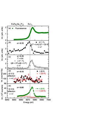
To confirm the resonant magnetic behavior of the peaks, we performed energy scans at the Eu L3 absorption edge as shown in Fig. 3. We note that for the (2 1 7) reflection charge and magnetic peak coincide. An investigation of the magnetic signal which is five to six orders of magnitude weaker than the Thomson charge scattering requires significant reduction of the charge background. The charge background can be reduced significantly for a reflection with scattering angle close to 90∘ Nandi et al. (2011); Kim et al. (2007). Since the (2 1 7) reflection has a scattering angle of at the Eu L3 edge, the investigation of the magnetic signal seems feasible for this reflection. Figure 3(b) shows an energy scan through the (2 1 7) reflection after subtracting the nonmagnetic background at T = 22 K. A clear resonance enhancement can be seen close to the Eu L3 edge. A similar resonance enhancement can be observed in the scattering channel in an applied magnetic field of 3 T. In both energy scans, the resonance peaks appear at and above the Eu L3 absorption edge, indicating the dipole nature of the transition. Figure 3 (d) shows energy scans through the antiferromagnetic (0 0 3) position, expected for an A-type AFM structure, for the 15% doped sample in the scattering channel. For comparison, we also show the energy scan through the (0 0 9) position in Fig. 3(e) for the 5% doped sample measured under similar conditions. A strong antiferromagnetic signal was observed for the 5% doped sample at the A-type AFM position which is in contrast to the 15% doped sample where no magnetic signal was observed. Therefore, the proposed A-type AFM structure Zapf et al. (2011) could not be confirmed for the superconducting 15% P-doped sample. This might be due to the small moment in the A-type AFM structure together with the glassy freezing of the in-plane component as suggested by Ref. Zapf et al., 2013.
III.3 Magnetic structure in zero and applied magnetic fields
| IR | Atom | BV components | Magnetic Intensity | |||
| (2 1 7) | ||||||
| 1 | 1 | 0 | 0 | Yes | Yes | |
| 1 | 0 | 1 | 0 | Yes | Yes | |
| 1 | 0 | 0 | 1 | Yes | No | |
We now turn to the determination of the magnetic moment configuration for the Eu2+ moments in the zero and applied magnetic fields. For the crystallographic space group Fmmm and = (0 0 0), three independent magnetic representations (MRs) are possible Wills (2000). Here we note that only ferromagnetic structures with magnetic moments along the three crystallographic directions a, b, c are allowed by symmetry. No antiferromagnetic structure with = (0 0 0) is possible in this case for symmetry reasons. All the MRs along with the calculated intensities for different polarization geometries are listed in Table 1.
The resonant scattering of interest, at the Eu L3 absorption edge, is due to electric dipole transitions between the core 2p states and the 5d conduction bands. The 5d bands are spin polarized through the exchange interaction with the magnetic 4f electrons. The resonant magnetic scattering cross-section for the dipole resonance can be written as Hill and McMorrow (1996):
| (2) |
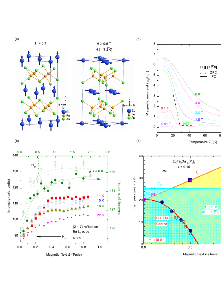
where is a unit vector in the direction of the magnetic moment of the nth ion. Here and are the incident and scattered polarization vectors, and ’s are the terms containing dipole matrix elements. The first term of Eq. 2 contributes to the charge Bragg peak as it does not contain any dependence on the magnetic moment. The other two terms are sensitive to the magnetic moment. For a ferromagnetic structure, in general all terms contribute to the scattering at every Bragg reflection. However, for the Eu2+ ions with spin only magnetic moment, the spherical symmetry of the spin-polarized 5d band ensures that the F(2) term is zero Hamrick (1990). For the scattering geometry the scattering amplitude from Eq. 2 can be written in a simplified form as , Nandi (2012) where and are the wave vector of the incoming photons and the magnetic moment, respectively. Clearly, the magnetic signal is sensitive to the component of the ordered moment in the scattering plane i.e. a/b and c components. For the scattering geometry the scattering amplitude can be written as , Nandi (2012) where is the wave vector of the outgoing photons. Therefore, in the scattering geometry, the magnetic signal is sensitive to the component of the ordered moment perpendicular to the scattering plane i.e. only a/b components. Since, no magnetic signal was observed in the scattering channel at zero field (see Fig. 2(b)), we conclude that the magnetic moments are aligned primarily along the c axis. For the applied magnetic field the situation is reversed. The magnetic signal is observed only in the scattering channel (see Fig. 2(c)) indicating the magnetic moments are in the a-b plane. It is most likely that the magnetic moments are along the applied filed direction i.e. along the [1 0] direction. The determined magnetic structures based on the polarization analysis of the scattered signal is presented in Fig. 4(a).
Having determined the magnetic structures in zero and applied magnetic fields, we have measured the field dependencies of the integrated intensity of the magnetic (2 1 7) reflection for several temperatures which are presented in Fig. 4 (b). A clear hysteresis can be seen from the increasing and decreasing field cycles at T = 6 K which is typical for a ferromagnet. The critical field, Hcr, at which the field induced phase transition occurs, has been determined from the intercept of the high and low field linear interpolation as shown for the T = 11 K measurement in Fig. 4 (b). The field dependence of the ferromagnetic ordering temperature has been determined from the temperature dependence of the (2 1 7) reflection in the scattering geometry as shown in Fig. 2(c). Additionally, isothermal magnetization (M-H) at different temperatures (not shown) and temperature dependencies of magnetization (M-T) at different magnetic fields (see Fig. 4(c)) have been performed to verify the transition temperatures and critical fields obtained from the scattering measurements. A combined phase diagram has been constructed and is shown in Fig. 4(d). It can be seen that superconductivity coexists with strong ferromagnetic order of the Eu2+ moments for a large region of the phase diagram. For B 0.5 T, the superconducting transition precedes the ferromagnetic transition, whereas the situation is reversed for magnetic fields higher than 0.5 T.
IV Discussion and Conclusion
The most important result of the present study is the observation of strong ferromagnetic order of the Eu2+ moments coexisting with bulk superconductivity. Magnetization, specific heat and temperature dependence of the structural distortion indicates bulk nature of the superconducting transition. In contrast to the previous studies, we got no indication of the proposed A-type AFM structure or a spiral magnetic order with propagation vector of the form (0 0 ) 222Careful scans along [0 0 L] direction do not reveal any magnetic peak.. In the Fe-As based superconductors, it is believed that the superconducting carriers are in the Fe-As layers. Therefore, to understand the phenomena of coexistence, we have calculated the effective field due the Eu2+ moments at the Fe-As layers using dipole approximation. To a first approximation, the dipole field does not exceed 1 T which is much less than the superconducting upper critical field H (~ 40 T) Johnston (2010) but higher than the lower critical field H (~ 0.02-0.03 T) Sefat et al. (2008). Since the internal field is between H and H, it is most likely that the EuFe2(As1-xPx)2 is in a spontaneous vortex state similar to which have been proposed in Eu(Fe0.75Ru0.25)2As2 Jiao et al. (2011) and UCoGe superconductors Deguchi et al. (2010). At an applied magnetic field, it is most likely that the vortices in the zero-field state (along the c axis) will gradually change along the applied field direction i.e. in the a-b plane.
In conclusion, the magnetic structure of the Eu moments in superconducting EuFe2(As1-xPx)2 with has been determined using element specific x-ray resonant magnetic scattering. Combining magnetic, thermodynamic and scattering measurements we conclude that the long range ferromagnetic order of the Eu2+ moments aligned primarily along the c axis coexists with the bulk superconductivity. The proposed canted antiferromagnetic order or spiral order could not be confirmed in the superconducting sample. Additional measurements such as small angle neutron scattering is needed to confirm the existence of a spontaneous vortex state.
Acknowledgements.
S. N. likes to acknowledge B. Schmitz and S. Das for technical assistance, S. Zapf and M. Dressel for fruitful discussion. Work at Göttingen was supported by the German Science Foundation through SPP 1458.References
- Kamihara et al. (2008) Y. Kamihara, T. Watanabe, M. Hirano, and H. Hosono, J. Am. Chem. Soc. 130, 3296 (2008).
- Johnston (2010) D. C. Johnston, Adv. Phys. 59, 803 (2010).
- Takahashi et al. (2008) H. Takahashi, K. Igawa, K. Arii, Y. Kamihara, M. Hirano, and H. Hosono, Nature (London) 453, 376 (2008).
- Chen et al. (2008) X. H. Chen, T. Wu, G. Wu, R. H. Liu, H. Chen, and D. F. Fang, Nature 453, 761 (2008).
- Zhi-An et al. (2008) R. Zhi-An, L. Wei, Y. Jie, Y. Wei, S. Xiao-Li, Zheng-Cai, C. Guang-Can, D. Xiao-Li, S. Li-Ling, Z. Fang, et al., Chin. Phys. Lett. 25, 2215 (2008).
- Rotter et al. (2008) M. Rotter, M. Tegel, and D. Johrendt, Phys. Rev. Lett. 101, 107006 (2008).
- Jeevan et al. (2008) H. S. Jeevan, Z. Hossain, D. Kasinathan, H. Rosner, C. Geibel, and P. Gegenwart, Phys. Rev. B 78, 092406 (2008).
- Sasmal et al. (2008) K. Sasmal, B. Lv, B. Lorenz, A. M. Guloy, F. Chen, Y.-Y. Xue, and C.-W. Chu, Phys. Rev. Lett. 101, 107007 (2008).
- Hsu et al. (2008) F.-C. Hsu, J.-Y. Luo, K.-W. Yeh, T.-K. Chen, T.-W. Huang, P. M. Wu, Y.-C. Lee, Y.-L. Huang, Y.-Y. Chu, D.-C. Yan, et al., Proc. Natl. Acad. Sci. 105, 14262 (2008).
- Guo et al. (2010) J. Guo, S. Jin, G. Wang, S. Wang, K. Zhu, T. Zhou, M. He, and X. Chen, Phys. Rev. B 82, 180520 (2010).
- Leithe-Jasper et al. (2008) A. Leithe-Jasper, W. Schnelle, C. Geibel, and H. Rosner, Phys. Rev. Lett. 101, 207004 (2008).
- Sefat et al. (2008) A. S. Sefat, R. Jin, M. A. McGuire, B. C. Sales, D. J. Singh, and D. Mandrus, Phys. Rev. Lett. 101, 117004 (2008).
- Schnelle et al. (2009) W. Schnelle, A. Leithe-Jasper, R. Gumeniuk, U. Burkhardt, D. Kasinathan, and H. Rosner, Phys. Rev. B 79, 214516 (2009).
- Wang et al. (2009) C. Wang, S. Jiang, Q. Tao, Z. Ren, Y. Li, L. Li, C. Feng, J. Dai, G. Cao, and Z. an Xu, Europhys. Lett. 86, 47002 (2009).
- Jiang et al. (2009) S. Jiang, H. Xing, G. Xuan, C. Wang, Z. Ren, C. Feng, J. Dai, Z. Xu, and G. Cao, J. Phys.: Condens. Mat. 21, 382203 (2009).
- Miclea et al. (2009) C. F. Miclea, M. Nicklas, H. S. Jeevan, D. Kasinathan, Z. Hossain, H. Rosner, P. Gegenwart, C. Geibel, and F. Steglich, Phys. Rev. B 79, 212509 (2009).
- Tokiwa et al. (2012) Y. Tokiwa, S.-H. Hübner, O. Beck, H. S. Jeevan, and P. Gegenwart, Phys. Rev. B 86, 220505 (2012).
- Marchand and Jeitschko (1978) R. Marchand and W. Jeitschko, J. Solid State Chem. 24, 351 (1978).
- Herrero-Martín et al. (2009) J. Herrero-Martín, V. Scagnoli, C. Mazzoli, Y. Su, R. Mittal, Y. Xiao, T. Brueckel, N. Kumar, S. K. Dhar, A. Thamizhavel, et al., Phys. Rev. B 80, 134411 (2009).
- Xiao et al. (2009) Y. Xiao, Y. Su, M. Meven, R. Mittal, C. M. N. Kumar, T. Chatterji, S. Price, J. Persson, N. Kumar, S. K. Dhar, et al., Phys. Rev. B 80, 174424 (2009).
- Xiao et al. (2010) Y. Xiao, Y. Su, W. Schmidt, K. Schmalzl, C. M. N. Kumar, S. Price, T. Chatterji, R. Mittal, L. J. Chang, S. Nandi, et al., Phys. Rev. B 81, 220406 (2010).
- Qi et al. (2008) Y. Qi, Z. Gao, L. Wang, D. Wang, X. Zhang, and Y. Ma, New J. Phys. 10, 123003 (2008).
- Ren et al. (2009) Z. Ren, Q. Tao, S. Jiang, C. Feng, C. Wang, J. Dai, G. Cao, and Z. Xu, Phys. Rev. Lett. 102, 137002 (2009).
- Terashima et al. (2009) T. Terashima, M. Kimata, H. Satsukawa, A. Harada, K. Hazama, S. Uji, H. S. Suzuki, T. Matsumoto, and K. Murata, J. Phys. Soc. Jpn. 78, 083701 (2009).
- Cao et al. (2011) G. Cao, S. Xu, Z. Ren, S. Jiang, C. Feng, and Z. Xu, J. Phys.: Condens. Mat. 23, 464204 (2011).
- Ahmed et al. (2010) A. Ahmed, M. Itou, S. Xu, Z. Xu, G. Cao, Y. Sakurai, J. Penner-Hahn, and A. Deb, Phys. Rev. Lett. 105, 207003 (2010).
- Nowik et al. (2011) I. Nowik, I. Felner, Z. Ren, G. H. Cao, and Z. A. Xu, J. Phys.: Condens. Mat. 23, 065701 (2011).
- Zapf et al. (2011) S. Zapf, D. Wu, L. Bogani, H. S. Jeevan, P. Gegenwart, and M. Dressel, Phys. Rev. B 84, 140503 (2011).
- Zapf et al. (2013) S. Zapf, H. S. Jeevan, T. Ivek, F. Pfister, F. Klingert, S. Jiang, D. Wu, P. Gegenwart, R. K. Kremer, and M. Dressel, Phys. Rev. Lett. 110, 237002 (2013).
- Anderson and Suhl (1959) P. W. Anderson and H. Suhl, Phys. Rev. 116, 898 (1959).
- Greenside et al. (1981) H. S. Greenside, E. I. Blount, and C. M. Varma, Phys. Rev. Lett. 46, 49 (1981).
- Ryan et al. (2011) D. H. Ryan, J. M. Cadogan, S. Xu, Z. Xu, and G. Cao, Phys. Rev. B 83, 132403 (2011).
- Jeevan et al. (2011) H. S. Jeevan, D. Kasinathan, H. Rosner, and P. Gegenwart, Phys. Rev. B 83, 054511 (2011).
- Strempfer et al. (2013) J. Strempfer, S. Francoual, D. Reuther, D. K. Shukla, A. Skaugen, H. Schulte-Schrepping, T. Kracht, and H. Franz, J. Synchrotron Rad. 20, 541 (2013).
- Osborn (1945) J. A. Osborn, Phys. Rev. 67, 351 (1945).
- Feng et al. (2010) C. Feng, Z. Ren, S. Xu, S. Jiang, Z. Xu, G. Cao, I. Nowik, I. Felner, K. Matsubayashi, and Y. Uwatoko, Phys. Rev. B 82, 094426 (2010).
- Prozorov et al. (2008) R. Prozorov, N. Ni, M. A. Tanatar, V. G. Kogan, R. T. Gordon, C. Martin, E. C. Blomberg, P. Prommapan, J. Q. Yan, S. L. Bud’ko, et al., Phys. Rev. B 78, 224506 (2008).
- Bean (1962) C. P. Bean, Phys. Rev. Lett. 8, 250 (1962).
- Kim et al. (1963) Y. B. Kim, C. F. Hempstead, and A. R. Strnad, Phys. Rev. 129, 528 (1963).
- Fietz et al. (1964) W. A. Fietz, M. R. Beasley, J. Silcox, and W. W. Webb, Phys. Rev. 136, A335 (1964).
- Ni et al. (2008) N. Ni, S. L. Bud’ko, A. Kreyssig, S. Nandi, G. E. Rustan, A. I. Goldman, S. Gupta, J. D. Corbett, A. Kracher, and P. C. Canfield, Phys. Rev. B 78, 014507 (2008).
- Nandi et al. (2010) S. Nandi, M. G. Kim, A. Kreyssig, R. M. Fernandes, D. K. Pratt, A. Thaler, N. Ni, S. L. Bud’ko, P. C. Canfield, J. Schmalian, et al., Phys. Rev. Lett. 104, 057006 (2010).
- Nandi et al. (2011) S. Nandi, Y. Su, Y. Xiao, S. Price, X. F. Wang, X. H. Chen, J. Herrero-Martin, C. Mazzoli, H. C. Walker, L. Paolasini, et al., Phys. Rev. B 84, 054419 (2011).
- Kim et al. (2007) J. W. Kim, A. Kreyssig, P. Ryan, E. Mun, P. C. Canfield, and A. I. Goldman, Appl. Phys. Lett. 90, 202501 (2007).
- Wills (2000) A. S. Wills, Physica B 276-278, 680 (2000).
- Hill and McMorrow (1996) J. P. Hill and D. F. McMorrow, Acta Crystallogr. A52, 236 (1996).
- Hamrick (1990) M. D. Hamrick, M. A. Thesis, Rice University (1990).
- Nandi (2012) S. Nandi, Magnetic x-ray scattering (John Wiley & Sons, New York, 2012).
- Jiao et al. (2011) W.-H. Jiao, Q. Tao, J.-K. Bao, Y.-L. Sun, C.-M. Feng, Z.-A. Xu, I. Nowik, I. Felner, and G.-H. Cao, Europhys. Lett. 95, 67007 (2011).
- Deguchi et al. (2010) K. Deguchi, E. Osaki, S. Ban, N. Tamura, Y. Simura, T. Sakakibara, I. Satoh, and N. K. Sato, J. Phys. Soc. Jpn. 79, 083708 (2010).