Dynamics and microinstabilities at perpendicular collisionless shock: A comparison of large-scale two-dimensional full particle simulations with different ion to electron mass ratio
Abstract
Large-scale two-dimensional (2D) full particle-in-cell simulations are carried out for studying the relationship between the dynamics of a perpendicular shock and microinstabilities generated at the shock foot. The structure and dynamics of collisionless shocks are generally determined by Alfven Mach number and plasma beta, while microinstabilities at the shock foot are controlled by the ratio of the upstream bulk velocity to the electron thermal velocity and the ratio of the plasma-to-cyclotron frequency. With a fixed Alfven Mach number and plasma beta, the ratio of the upstream bulk velocity to the electron thermal velocity is given as a function of the ion-to-electron mass ratio. The present 2D full PIC simulations with a relatively low Alfven Mach number () show that the modified two-stream instability is dominant with higher ion-to-electron mass ratios. It is also confirmed that waves propagating downstream are more enhanced at the shock foot near the shock ramp as the mass ratio becomes higher. The result suggests that these waves play a role in the modification of the dynamics of collisionless shocks through the interaction with shock front ripples.
pacs:
52.35.Tc; 52.35.Qz; 52.65.-y; 52.65.Rr;I Introduction
Collisionless shocks have been investigated by full Particle-In-Cell (PIC) simulations for more than four decades since early 1970’s Biskamp_1972 . The full PIC method handles both electron-scale microphysics and ion-scale shock nonstationarity (i.e., spatiotemporal variation) simultaneously, since both electrons and ions are treated as individual charged particles. However, smaller simulation systems and reduced parameters (such as the ion-to-electron mass ratio , the electron plasma-to-cyclotron frequency ratio , and the speed of light relative to the electron thermal velocity ratio ) were used in past simulation studies to save the computational cost.
Since early one-dimensional (1D) simulations (e.g., Biskamp_1972, ; Quest_1985, ; Lembege_1987, ), it has been well known that the shock front at supercritical (quasi-)perpendicular collisionless shocks becomes nonstationary. Incoming ions are decelerated and accumulated at the shock front. Then, a part of them are reflected upstream periodically. This coherent behavior of incoming ions results in the periodic collapse and redevelopment of the shock front, which is called the self-reformation. Later, the existence of the reformation in the two-dimensional (2D) system was also confirmed by a full PIC simulation Lembege_1992 .
It has been known that various types of microinstabilites are generated at the shock foot of perpendicular and quasi-perpendicular shocks during the broadening phase of the shock reformation when a part of incoming ions are reflected upstream. The ion reflection results in the deceleration of incoming electrons so that the conservation of the total current (the zero current condition in the shock normal direction) is satisfied. Consequently, there arises a relative drift velocity between the incoming electrons and the incoming/reflected ions, which is the free energy source of these microinstabilities. The ratio of the relative drift velocity to the electron thermal velocity is important for controlling the type of microinstabilities (or the effect of electron thermal damping to waves) Scholer_2003 ; Scholer_2004 . This ratio is proportional to the ratio of the upstream bulk velocity to the electron thermal velocity. Past self-consistent kinetic simulation studies revealed that there exist various types of microinstabilities in the shock foot region of perpendicular and quasi-perpendicular shocks.
Structures and dynamics of shock waves are generally determined by the following two dimensionless parameters, i.e., Alfven Mach number
| (1) |
and the plasma beta (the ratio of the thermal plasma pressure to the magnetic pressure)
| (2) |
where , , , and represent the speed of light, bulk velocity, plasma frequency, cyclotron frequency and thermal velocity, respectively, with the subscripts “” and “” being ion and electron, respectively. Here the subscript “1” denotes the upstream. From these definitions of the Alfven Mach number and the electron beta, we obtain the ratio of the upstream bulk velocity to the electron thermal velocity, which determines the type of microinstabilities in the shock foot region,
| (3) |
This relation means that the ratio of the upstream bulk velocity to the electron thermal velocity becomes larger with larger Alfven Mach number, smaller electron beta, or smaller mass ratio. Note that the actual amount of free energy relative to the electron thermal energy () is independent of the mass ratio.
The relative bulk velocity between electrons and ions (which is proportional to ) controls the type of microinstabilities, while the ratio of the plasma-to-cyclotron frequency () determines the dispersion relation of plasma waves. When the relative bulk velocity between electrons and ions exceeds the electron thermal velocity, electrostatic waves are excited by current-driven instabilities such as the Buneman-type instability (BI) Buneman_1958 or the electron cyclotron drift instability (ECDI) Wong_1970 ; Forslund_1970 . At high-Mach-number perpendicular shocks, the relative velocity between incoming electrons and reflected ions commonly becomes much faster than the electron thermal velocity. Then, the BI becomes dominant, and electrostatic waves are excited at the upper hybrid resonance frequency Shimada_2000 . At lower-Mach-number () perpendicular shocks, the relative velocity between incoming electrons and incoming/reflected ions becomes close to the electron thermal velocity. Then, the growth rate of the BI becomes small because of the damping by thermal electrons, and the ECDI becomes dominant, which excites electrostatic waves at multiple electron cyclotron harmonic frequencies Muschietti_2006 . When the relative velocity between incoming electrons and incoming/reflected ions becomes slower than the electron thermal velocity at lower-Mach-number perpendicular shocks, high-frequency electrostatic waves are not excited due to the damping by thermal electrons, and the modified two-stream instability (MTSI) Lashmore_1971 ; Krall_1971 ; Ott_1972 ; McBride_1972a ; McBride_1972b becomes dominant. Then, obliquely propagating electromagnetic whistler mode waves are excited at a frequency between the electron cyclotron frequency and the lower hybrid resonance frequency Wu_1983 ; Scholer_2003 ; Matsukiyo_2003 ; Scholer_2004 ; Matsukiyo_2006 ; Matsukiyo_2010 ; Umeda_2012a . Our previous study Umeda_2012b has clearly shown that for a relatively low Mach number () perpendicular shock the MTSI becomes dominant with higher mass ratios () while the ECDI becomes dominant with smaller mass ratio ().
Meanwhile, it has been also known by the early hybrid PIC simulations (e.g., Winske_1988, ) that large-amplitude fluctuations commonly exist along the shock overshoot in multidimensional systems, which is called as the “ripples.” A typical spatial scale of the shock-front ripples is ion inertial lengths in the shock-tangential direction. The ripples are thought to involve (L-mode) Alfven ion cyclotron waves excited by ion temperature anisotropy at the shock front Winske_1988 . So far, it has been difficult to perform 2D full PIC simulations including the shock-front ripples, since current computer resources are not necessarily enough to cover a large simulation domain of several ion inertial lengths in the shock-tangential direction.
Development of computer technologies in recent days allows us to perform higher-resolution hybrid 2D PIC and larger-scale 2D full PIC simulations with a longer simulation time. Recent 2D full PIC and hybrid PIC simulations of exactly perpendicular shocks Hellinger_2007 ; Lembege_2009 have suggested that the dynamics of collisionless shocks is modified by the ion-to-electron mass ratio. It has been demonstrated that the reformation is absent with the ion-to-electron mass ratio , while the reformation is suppressed with where the shock reformation is evident in an early phase but becomes apparently suppressed in a later phase. The difference in the shock dynamics with different mass ratios in the previous studies was discussed in terms of the excitation of “nonlinear whistler waves” at the shock front.
Our previous study Umeda_2012b has confirmed that the mass ratio controls microinstabilities in the shock foot region. However, the generation of the ripples at the shock front was not included in our previous study, because the system length in the shock-tangential direction was too short. The purposes of the present study are to perform a large-scale 2D simulation including shock-front ripples for understanding the competition between the ripples and microinstabilities and to make a direct comparison between simulation results with different ion-to-electron mass ratio. It should be noted that the existence of the shock reformation itself Yuan_2009 is not discussed in the present study.
The paper is organized as follows. Section II describes the model and the parameters of full PIC simulations. Section III shows the simulation results, and section IV gives conclusion and discussion of the present study.
II Simulation Setup
We use a 2D electromagnetic full particle code in which the full set of Maxwell’s equations and the relativistic equation of motion for individual electrons and ions are solved in a self-consistent manner. The continuity equation for charge is also solved to compute the exact current density given by the motion of charged particles Umeda_2003 . In the present simulation, the simulation domain is taken in the shock-rest frame (e.g., Leroy_1981, ; Leroy_1982, ; Muschietti_2006, ; Umeda_2006, ). A collisionless shock is excited by the “relaxation” between a supersonic plasma flow and a subsonic plasma flow moving in the same direction. The detailed initial setup is described in Refs. Umeda_2008 ; Umeda_2009 .
In the present study, we assume a low-Mach number (), moderate beta (), weakly-magnetized (), and perpendicular () collisionless shock as shown in Table 1. Here, subscripts “1” and “2” denote “upstream” and “downstream”, respectively. We take the simulation domain in the - plane and assume an in-plane shock magnetic field (). As a motional electric field, a uniform external electric field is applied in both upstream and downstream regions, so that both electrons and ions drift along the axis. At the left boundary of the simulation domain in the direction, we inject plasmas with the same quantities as those in the initial upstream region, while plasmas with the same quantities as those in the initial downstream region are also injected from the right boundary in the direction. We use absorbing boundaries to suppress non-physical reflection of electromagnetic waves at both ends of the simulation domain in the direction Umeda_2001 , while the periodic boundaries are imposed in the direction.
| Authors | Code | ||||||
|---|---|---|---|---|---|---|---|
| Run A (Present) | full PIC | 6.5 | 0.32 | 0.32 | 25 | 4 | |
| Run B (Present) | full PIC | 6.58 | 0.32 | 0.32 | 100 | 4 | |
| Run C (Present) | full PIC | 6.58 | 0.32 | 0.32 | 256 | 4 | |
| Run D (Present) | full PIC | 6.58 | 0.32 | 0.32 | 625 | 4 | |
| Hellinger et al. Hellinger_2007 | Hybrid | 3.6 | 0.2 | 0.5 | |||
| Lembege et al. Lembege_2009 | full PIC | 4.93 | 0.15 | 0.24 | 400 | 2 | |
| – | full PIC | 4.93 | 0.15 | 0.24 | 42 | 2 | |
| Umeda et al. Umeda_2009 ; Umeda_2010 ; Umeda_2011 | full PIC | 5.5 | 0.125 | 0.125 | 25 | 10 |
We performed four simulation runs (A, B, C and D) with different ion-to-electron mass ratio 25, 100, 256 and 625, respectively. The grid spacing and the time step of the present simulation runs are set to be and . Here is the electron Debye length. The total size of the simulation domain is , where is the ion inertial length (, , and in Runs A, B, C and D, respectively). The bulk flow velocity of the upstream plasma is 3.0, 1.5, 0.9375 and 0.6 in Runs A, B, C and D, respectively (), which controls the free energy source for microinstabilities in the shock foot region. Note that the previous small-scale 2D full PIC simulations (without ripples) Umeda_2012b have confirmed that the ECDI is dominant with the parameters for Run A while the MTSI is dominant with the parameters for Runs B–D.
The initial state consists of two uniform regions separated by a discontinuity. In the upstream region that is taken in the left-hand side of the simulation domain, electrons and ions are distributed uniformly in space and are given random velocities to approximate shifted Maxwellian momentum distributions with the drift velocity , number density , isotropic temperatures and , where , , and are the mass, charge, plasma frequency and thermal velocity, respectively. The upstream magnetic field with a magnitude of is also assumed to be uniform, where is the cyclotron frequency. The downstream region taken in the right-hand side of the simulation domain is prepared similarly with the drift velocity , density , isotropic temperatures and , and magnetic field .
In the relaxation method, the initial condition is given by solving the shock jump conditions (Rankine-Hugoniot conditions) for a magnetized two-fluid isotropic plasma consisting of electrons and ions Hudson_1970 . In order to determine a unique initial downstream state, we need given upstream quantities , , , , , and . Note that the initial downstream ion-to-electron temperature ratio is assumed to solve the jump condition for a unique initial quantities of the downstream plasma. It should be noted that a shock wave is excited by the relaxation of the two plasmas with different quantities in the present shock-rest-frame model. Since the initial state is given by the shock jump conditions for a “two-fluid” plasma consisting of electrons and ions Hudson_1970 , however, the kinetic effect is excluded in the initial state and it is very difficult to construct an exact shock rest frame. Then, the shock front of the excited shock moves upstream at a slow velocity (), as we will show later. Thus, the Mach number should be corrected as shown in Table 1.
We used 25 pairs of electrons and ions per cell in the upstream region and 64 pairs of electrons and ions per cell in the downstream region, respectively, at the initial state.
III Results
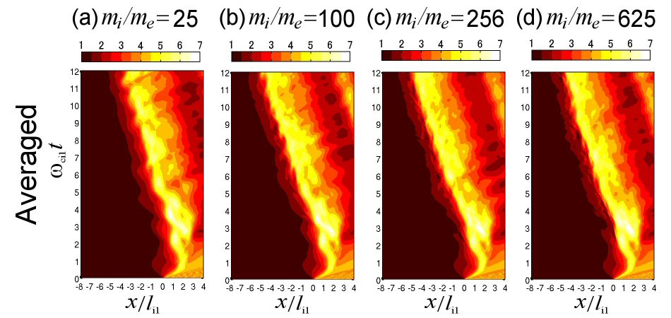
Figure 1 shows the tangential component of the shock magnetic field () for Runs A–D as a function of position and time . The position and time are renormalized by the ion inertial length and the ion cyclotron angular period , respectively. The magnitude is normalized by the initial upstream magnetic field . In Fig.1, the magnetic field is “averaged” over the direction, which means that fluctuations in the shock-tangential direction are smoothed out.
In all the runs, the shock overshoot () appears at and 3.6. After that, however, these runs show different development. In Run A, a strong magnetic field () appears at and 6.8, and then the oscillation becomes smaller and smaller. This is similar to the previous studyLembege_2009 , which reported the (nonphysical) suppression of the reformation in the result with . It is noted that the previous study Umeda_2010 with demonstrated that the quasi-periodic oscillation of the shock overshoot gradually disappears when the magnetic field is averaged over the shock tangential direction. However, this fact does not necessarily mean the non-existence of the shock reformation.
In Run B, a strong magnetic field () appears at and 7.5, and then the oscillation becomes smaller and smaller. There also appears a small-scale (smaller than the ion scale) structure at the shock front (shock foot). By contrast, a strong magnetic field () appears at in Run C and in Run D, but the quasi-periodic oscillation of the shock overshoot is not evident. This is similar to the previous studyLembege_2009 , which reported the absence of the reformation in the result with . There also appear smaller-scale structures at the shock front (shock foot) in Runs C and D.
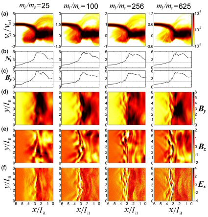
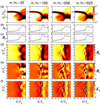
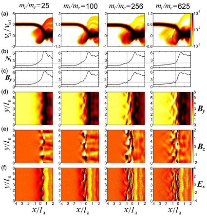
Figure 2 shows a typical structure of the perpendicular shock transition region for Runs A–D at a quasi-steady state (). The panel (a) shows the -averaged phase space density of ions. The panels (b) and (c) show the -averaged ion density and shock magnetic field , respectively. The panels (d), (e) and (f) show the corresponding spatial profile of , and , respectively. In all the runs, a large-amplitude fluctuation with a wavelength of six ion inertial lengths exists in the magnetic field and components at the shock overshoot, which is identified as the ripples.
In Run A, we can see the characteristic signature of the shock transition region, i.e., foot, ramp, and overshoot. The spatial size of the foot region in Run A corresponds to the gyro radius of reflected ions, which is in this case. The typical ion density and shock magnetic field in the foot region is and , respectively. The spatial profiles of and respectively in panels (d) and (e) show that there are large-scale (ion-scale) waves at the shock front, which correspond to the rippled structure. The spatial profile of in panel (f) shows the excitation of electron-scale electrostatic waves (at ). It is expected that these waves are due to the ECDI generated by a localized ion beam Umeda_2009 ; Umeda_2011 .
The spatial profiles of , and in Runs B–D show the excitation of electron-scale electromagnetic waves, which implies oblique whistler waves due to the MTSI Matsukiyo_2003 ; Matsukiyo_2006 ; Umeda_2012a . The previous linear analysis Umeda_2012b has shown that the wavelength of the whistler waves becomes shorter as the mass ratio becomes higher, which is consistent with the present study. On the other hand, the generation of the MTSI is not so clear in Run A.
As the mass ratio becomes higher, the ion density and shock magnetic field in the foot region becomes smaller. The spatial size of the foot region also looks smaller as the mass ratio becomes higher. As seen in the panel (a) of Runs B–D, however, reflected ions are strongly scattered in the shock normal direction by the waves and spread over a wide range in the space, and a small part of reflected ions reach .
Figure 1 indicates that the dynamics of the shock front looks similar in all the runs until but becomes different after . Figure 3 shows a structure of the shock transition region for Runs A–D at a transient phase (). There is a difference in the evolution of the shock front among these runs. In Run A, the shock front is kinking at Mode 2 in . In Run B, there appears a fluctuation at Mode 3 in , and in Runs C and D, the shock overshoot is modified at Mode 2 in . At the shock foot, there also appear small-scale wave activities near the shock ramp in Runs B–D. These small-scale waves are more enhanced as the mass ratio becomes higher.
Figure 4 shows a structure of the shock transition region for Runs A–D at an early phase (), when the periodic self-reformation is seen in Run A. In all the runs, there is a quasi-1D structure of the negative electric field component (i.e., shock potential) at the shock overshoot, implying that shock-front ripples are not generated at this time. There also appears a fluctuation in the magnetic field component around the shock overshoot at Mode 5, 4, 3, and 3 in in Run A, B, C, and D, respectively, which corresponds to L-mode cyclotron waves Winske_1988 and may develop into shock-front ripples. At the shock foot, there appears a fluctuation at Mode 3 in () and in Runs B and C. However, the fluctuation at Mode 3 in is not evident in Run D but small-scale fluctuations with various mode numbers are seen. The small-scale wave activities are also seen in Run C near the shock ramp, suggesting that the small-scale fluctuations are more enhanced as the mass ratio becomes higher. In Run A, there appears a fluctuation at Mode 3 in () around the shock ramp ().
Note that the excitation of waves due to the relative drift between ions and electrons at the shock foot region is discussed by many authors. It is suggested that there are two possible excitation types of instability at the shock foot due to incoming ions and reflected ions, which are referred as “instability-1” () and “instability-2” (), respectively Matsukiyo_2006 . The reflected ion component in the phase space plots in Figs3(a) and 4(a) shows phase-space vortices in Runs B–D, which indicate the excitation of waves due to microinstabilites (possibly by the MTSI-2). Simultaneously, the incoming ion component also shows modulation near the shock ramp in Runs B–D.
Our previous studies Umeda_2012a ; Umeda_2012b presented a series of small-scale 2D full PIC simulation with the same physical parameters but for different mass ratio. Also, a direct comparison was made between the simulation result and a linear analysis of waves excited at the shock foot due to incoming and reflected ions. An excellent agreement between the linear analysis and the simulation result was shown. However, since the simulation domain was shorter than the ion inertial length in the shock-tangential direction, shock-front ripples were not included. In the present large-scale simulations, by contrast, since shock front ripples generate an inhomogeneous reflected ion beam Umeda_2009 ; Umeda_2011 , the standard linear analysis (in which the spatial distribution of plasma is assumed to be uniform) is not directly applicable. However, we use the result of previous linear analysis Umeda_2012a ; Umeda_2012b as a reference of microinstabilites at the shock foot.
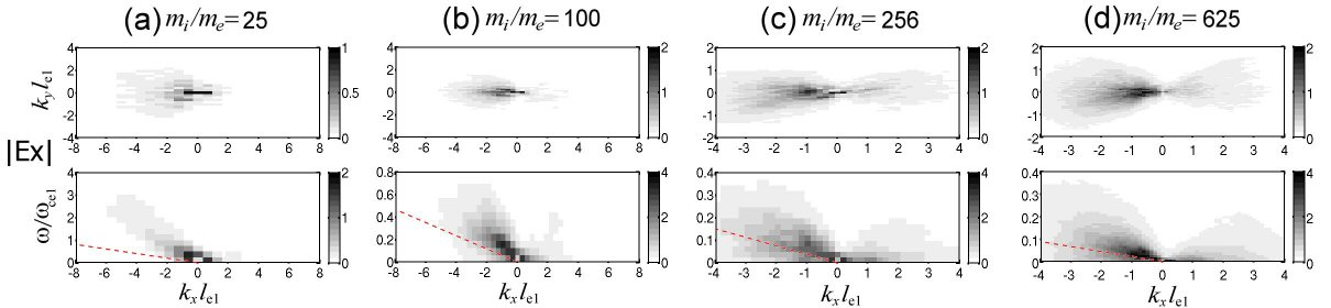
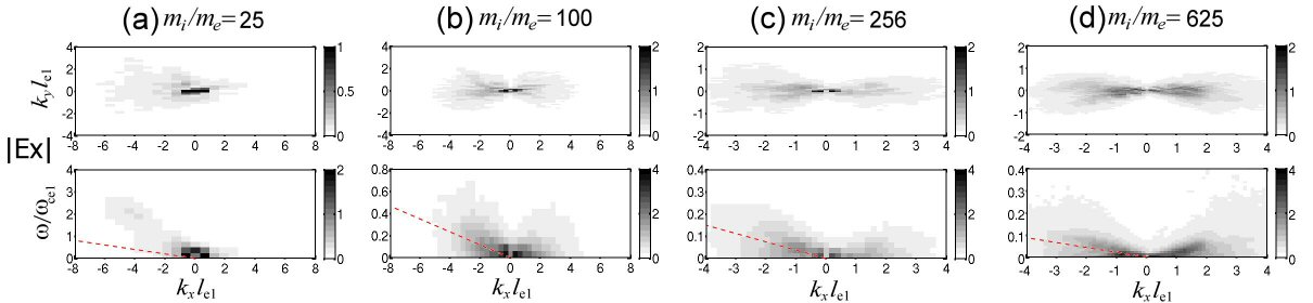
Figures 5, 6 and 7 show the spectral intensity of the electric field component in the shock foot region at different time intervals ( and for a time interval of for Fig.5, and for a time interval of for Fig.6, and and for a time interval of for Fig,7, respectively). The spectrum in the top panels and spectrum in the bottom panels are obtained by integrating the spectrum over and , respectively. The wave intensity is normalized by the motional electric field . The gradient of the dashed line indicates the speed of the shock wave ( for Run A, for Run B, for Run C, and for Run D, respectively). Note that the spectra in Fig.5 show more blurred feature than those of Fig.3 in Ref.Umeda_2012b due to the effect of integration in the larger region of .
At an early phase () in Fig.5, waves are generated in the direction (toward upstream). These waves are enhanced below the electron cyclotron frequency and above the lower hybrid resonance frequency ( 0.2, 0.1, 0.06 and 0.04 for Runs A, B, C and D, respectively). The phase velocities of these waves are faster than the speed of the shock wave ( for Run A, for Run B, for Run C, and for Run D, respectively). These phase velocities are close to (about 50–70% of) the drift velocity of reflected ions identified from Fig.4a. The previous linear analysis Umeda_2012b suggested that the MTSI-2 due to reflected ions is unstable for a various mass ratio at almost the same electron-scale wavenumber in the shock-normal direction and the same ion-scale wavenumber in the shock-tangential direction (see Fig.5 in Ref.Umeda_2012b ). The spectra in Fig.5 show that these waves are enhanced at and at ( 0.31, 0.2 and 0.13 for Runs B, C and D, respectively, which correspond to Mode 3 in ). It is confirmed that the oblique whistler waves are excited through the MTSI-2 due to reflected ions.
It is noted that the oblique whistler waves due to the MTSI-2 (at the shock foot) propagate at the phase velocity close to the drift velocity of reflected ions, while the L-mode cyclotron waves (at the shock ramp/overshoot) propagate at the phase velocity close to the propagation velocity of the shock wave. However, it is difficult to separate these waves in Run A because of the resolution in frequency space. In Run A, another high-frequency wave modes are also enhanced weakly above the electron cyclotron frequency. The phase velocity of this wave mode is much faster than the speed of the shock wave (), which is close to the drift velocity of reflected ions. The result suggests the generation of ECDI-2 due to reflected ions. Note that ECDI-2 was confirmed in the previous small-scale simulation study with Umeda_2012b , where electron cyclotron harmonic waves are enhanced at as predicted by the linear analysis (see Fig.3 in Ref.Umeda_2012b ). In the present large-scale simulation, on the other hand, the wave enhancement is not so strong and the spectrum spreads over a wide frequency range (). Here, the simulation result suggests the generation of the ECDI-2 is weakened by the modification of the linear dispersion relation due to the spatial inhomogeneity of the ion density.
It is also noted that in our previous small-scale 2D simulation (where shock-front ripples are not included), waves are strongly excited through the MTSI-2 (and the ECDI-2) but less through the MTSI-1 Umeda_2012b . In the present large-scale simulation (with shock-front ripples), by contrast, waves with are also weakly excited at the early phase (), which is possibly by the MTSI-1 due to incoming ions as indicated from the modification of the phase-space distribution of reflected ions in Fig.4(a).
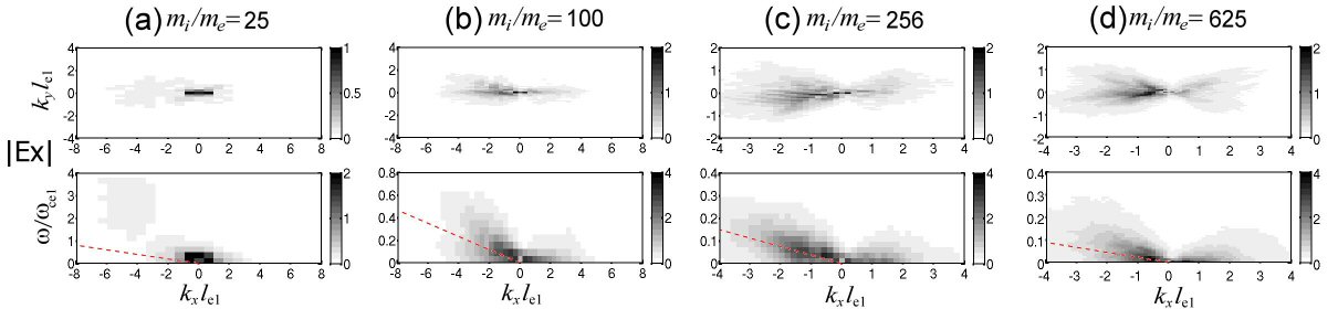
At a transient phase () in Fig.6, waves propagating downstream are enhanced more than in Fig.5. For Runs B, C and D ( 100, 256 and 625), phase velocities of low-frequency waves propagating upstream become close to the propagation speed of the shock wave rather than the drift velocity of reflected ions. For Run A (), phase velocities of high-frequency waves propagating upstream are still close to the drift velocity of reflected ions. However, the generation of the ECDI-2 becomes less evident, which is because of the “steepening phase” of the shock reformation.
The tendency of these wave characteristics becomes more evident at the quasi-steady phase () in Fig.7. As the mass ratio becomes higher, waves propagating downstream (generated by the MTSI-1) are more enhanced. As the mass ratio becomes higher, waves propagating upstream at the drift velocity of reflected ions (generated by the MTSI-2) become less evident but waves propagating upstream at the speed of the shock wave becomes more evident. For Run A (), however, waves propagating upstream at the drift velocity of reflected ions (generated by the ECDI-2) are well identified. The agreement between the present large-scale simulation and the previous linear analysis becomes worse at a later phase because the coherent behavior of reflected ions is suppressed by the spatial inhomogeneity in higher mass-ratio runs. As seen in phase-space plots in Figs. 3(a) and 4(a) for Run C () and Run D (), reflected ions are strongly scattered in the velocity space at the shock foot near the shock ramp, and the “beam” of reflected ions no longer exists.
IV Conclusion and Discussion
Our previous linear analysis and 2D full PIC simulations with a small simulation domain Umeda_2012b confirmed that the ion-to-electron mass ratio affects microinstabilities in the foot region of perpendicular collisionless shocks. However, the shock-front ripples were not included in the previous study. In the present study, we have performed 2D full PIC simulations with a large simulation domain to include both shock front ripples and microinstabilities simultaneously.
The previous linear analysisUmeda_2009 ; Umeda_2011 showed that the ECDI tends to be dominant with a low mass ratio, a low beta, or a low Mach number, and that the MTSI tends to be dominant with a high mass ratio, a high beta, or a low Mach number. The present large-scale 2D full PIC simulation shows a reasonable agreement with the linear analysis at an early phase of the simulation. However, the ECDI becomes weaker even for smaller mass ratio possibly due to the spatial inhomogeneity at the shock foot.
By contrast to the reasonable agreement between the present large-scale simulation and the previous linear analysis at the early phase, the agreement becomes worse as both nonlinearity and spatial inhomogeneity at the shock front develop. The generation of the MTSI-2 becomes less evident for high-mass-ratio runs since reflected ions are scattered at the shock foot near the shock ramp by strong wave-particle interactions. Then, the phase velocity of waves propagating upstream switches to the propagation speed of the shock wave from the drift velocity of reflected ions. In addition to these results, it is also confirmed that waves propagating downstream are enhanced stronger at the shock ramp as time elapses and as the mass ratio becomes higher, possibly by the MTSI-1 due to incoming ions. The present result suggests that the difference of the shock dynamics between high and low mass ratios is caused by the waves propagating downstream.
Present study showed how the global shock structure and the wave excitation around shock front change with different mass ratio. However, the simulation data is not enough to give complete answers for the property and origin of these waves, unfortunately. Nevertheless, we discuss unsolved issues of the relationship between the shock dynamics and the wave excitation which we believe most likely.
The previous studies Hellinger_2007 ; Lembege_2009 discussed the difference in the shock dynamics among different mass ratio in terms of the “nonlinear whistler waves,” which are excited at the shock front with but not with . Is the present study with higher mass ratios consistent with the previous results Hellinger_2007 ; Lembege_2009 ? Hellinger et al. Hellinger_2007 characterized the “nonlinear whistler waves” as oblique whistler waves at the shock foot with zero phase velocity in the shock rest frame. Figure 2a in Ref.Hellinger_2007 shows that the waves with and are enhanced at both shock foot and shock ramp. Figure 2c in Ref.Lembege_2009 shows that waves with and are enhanced at the shock foot and waves with and are enhanced at the shock ramp. It is expected that the former one (at the shock foot) corresponds to the “nonlinear whistler waves” and that the latter one (at the shock ramp) corresponds to the shock-front ripples. In the present simulations, it is clearly shown by the spectra that there exist waves propagating at the propagating velocity of the shock wave. The spectrum at the quasi-steady phase (in Fig.7) shows that the waves are most enhanced at and for 625 and 256 ( 0.25 and 0.4 for 625 and 256, respectively). These characteristics are very similar to the “nonlinear whistler waves” seen in the previous studies Hellinger_2007 ; Lembege_2009 .
However, the generation mechanism of the nonlinear whistler waves is still unclear. Although Hellinger et al. Hellinger_2007 proposed a fluid-like nonlinear three-wave coupling, it is difficult to identify this process in the present study. As Hellinger et al. Hellinger_2007 denied the direct generation by the beam of reflected ions (i.e., MTSI-2), reflected ions are strongly scattered in the velocity space at the shock foot near the shock ramp, possibly by the nonlinear whistler waves, and the beam of reflected ions no longer exists for higher-mass-ratio runs in the present study. Here, we suggest the importance of the waves propagating downstream at the shock foot. As seen in the phase-space plots for higher-mass-ratio runs (Fig.2(a)), incoming ions are modulated and reflected ions are strongly scattered in the velocity space at the shock foot near the shock ramp. An alternative generation mechanism suggested in the present study is a kinetic wave-wave interaction in the phase space: the merging between phase-space vortices of large-amplitude (nonlinear) waves propagating upstream and downstream (generated by the MTSI-2 and MTSI-1, respectively), which may generate a large-amplitude phase-space vortices which is almost at rest in the shock frame. In order to confirm this process, however, a further investigation is required.
Also, the issue of the absence/existence of the shock reformation discussed in the previous studies Hellinger_2007 ; Lembege_2009 ; Yuan_2009 is not addressed in the present study. This is because averaging the magnetic field over the shock tangential direction does not necessarily show the existence/absence of the shock reformation. Meanwhile, it is very difficult to define the shock reformation in multidimensional systems only from a local magnetic field Umeda_2010 . Here, we again suggest the importance of the waves propagating downstream at the shock foot. The waves generated by microinstabilities (MTSIs) have an electron-scale wavelength in the shock normal direction but an ion-scale wavelength in the shock tangential direction. Hence, it is possible that the waves propagating downstream generated by the MTSI-1 interact with the L-mode Alfven cyclotron waves at the shock overshoot, which may result in the modification in the development of shock front ripples at the transition phase. Although this issue needs further parameter surveys for various Alfven Mach numbers and various plasma beta which should be left as a future study, the present result has indicated that microinstabilities play a role in the modification of collisionless shock dynamics among different ion-to-electron mass ratio.
Acknowledgements.
This work was supported by MEXT/JSPS under Grant-in-Aid for Scientific Research on Innovative Areas No.21200050, Grant-in-Aid for Young Scientists (B) No.22740323 (S. M.) and No.21740184 (R. Y.). The computer simulations were performed on the DELL PowerEdge R815 supercomputer system at the Solar-Terrestrial Environment Laboratory (STEL) and the Fujitsu FX1 and HX600 supercomputer systems at the Information Technology Center (ITC), Nagoya University, as a STEL computational research program, a Nagoya University HPC research program, a JHPCN program at Joint Usage/Research Center for Interdisciplinary Large-scale Information Infrastructures, and a HPCI systems research project.References
- (1) D. Biskamp and H. Welter, Nuclear Fusion 12, 663 (1972).
- (2) K. B. Quest, Phys. Rev. Lett. 54, 1872 (1985).
- (3) B. Lembege and J. M. Dawson, Phys. Fluids 30, 1767 (1987).
- (4) B. Lembege and P. Savoini, Phys. Fluids B 4, 3533(1992).
- (5) M. Scholer, I. Shinohara, and S. Matsukiyo, J. Geophys. Res. 108, 1014 (2003).
- (6) M. Scholer and S. Matsukiyo, Ann. Geophys. 22, 2345 (2004).
- (7) O. Buneman, Phys. Rev. Lett. 1, 8 (1958).
- (8) H. V. Wong, Phys. Fluids 13, 757 (1970).
- (9) D. W. Forslund, R. L. Morse, and C. W. Nielson, Phys. Rev. Lett. 25, 1266 (1970).
- (10) N. Shimada and M. Hoshino, Astrophys. J. 543, L67 (2000).
- (11) L. Muschietti and B. Lembege, Adv. Space Res. 37, 483 (2006).
- (12) N. A. Krall and P. C. Liewer, Phys. Rev. A 4, 2094 (1971).
- (13) C. N. Lashmore-Davies, Phys. Fluids 14, 1481 (1971).
- (14) E. Ott, J. B. McBride, J. H. Orens, and J. P. Boris, Phys. Rev. Lett. 28, 88 (1972).
- (15) J. B. McBride and E. Ott, Phys. Lett. 39A, 363 (1972).
- (16) J. B. McBride, E. Ott, J. P. Boris, and J. H. Orens, Phys. Fluids 15, 2367 (1972).
- (17) C. S. Wu, Y. M. Zhou, S. T. Tsai, S. C. Guo, D. Winske, and K. Papadopoulos, Phys. Fluids 26, 1259 (1983).
- (18) S. Matsukiyo and M. Scholer, J. Geophys. Res. 108, 1459 (2003).
- (19) S. Matsukiyo and M. Scholer, J. Geophys. Res. 111, A06104 (2006).
- (20) S. Matsukiyo, Phys. Plasmas 17, 042901 (2010).
- (21) T. Umeda, Y. Kidani, S. Matsukiyo, and R. Yamazaki, J. Geophys. Res. 117, A03206 (2012).
- (22) T. Umeda, Y. Kidani, S. Matsukiyo, and R. Yamazaki, Phys. Plasmas 19, 042109 (2012).
- (23) D. Winske and K. B. Quest, J. Geophys. Res. 93, 9681 (1988).
- (24) P. Hellinger, P. M. Travnicek, B. Lembege, and P. Savoini, Geophys. Res. Lett., 34, L14109 (2007).
- (25) B. Lembege, P. Savoini, P. Hellinger, and P. M. Travnicek, J. Geophys. Res., 114, A03217 (2009).
- (26) X. Yuan, I. H. Cairns, L. Trichtchenko, R. Rankin, and D. W. Danskin, iGeophys. Res. Lett. 36, L05103 (2009).
- (27) T. Umeda, Y. Omura, T. Tominaga, and H. Matsumoto, Comput. Phys. Commun. 156, 73 (2003).
- (28) M. M. Leroy, C. C. Goodrich, D. Winske, C. S. Wu, and K. Papadopoulos, Geophys. Res. Lett. 8, 1269 (1981).
- (29) M. M. Leroy, D. Winske, C. C. Goodrich, C. S. Wu, and K. Papadopoulos, J. Geophys. Res. 87, 5081 (1982).
- (30) T. Umeda and R. Yamazaki, Earth Planets Space 58, e41 (2006).
- (31) T. Umeda, M. Yamao, and R. Yamazaki, Astrophys. J. 681, L85 (2008).
- (32) T. Umeda, M. Yamao, and R. Yamazaki, Astrophys. J. 695, 574 (2009).
- (33) T. Umeda, Y. Omura, and H. Matsumoto, Comput. Phys. Commun. 137, 286 (2001).
- (34) P. D. Hudson, Planet. Space Sci. 18, 1611 (1970).
- (35) T. Umeda, Y. Kidani, M. Yamao, S. Matsukiyo, and R. Yamazaki, J. Geophys. Res. 115, A10250 (2010).
- (36) T. Umeda, M. Yamao, and R. Yamazaki, Planet. Space Sci. 59, 449 (2011).