Twisted magnetic flux tubes in the solar wind
Abstract
Magnetic flux tubes in the solar wind can be twisted as they are transported from the solar surface, where the tubes are twisted owing to photospheric motions. It is suggested that the twisted magnetic tubes can be detected as the variation of total (thermal+magnetic) pressure during their passage through observing satellite. We show that the total pressure of several observed twisted tubes resembles the theoretically expected profile. The twist of isolated magnetic tube may explain the observed abrupt changes of magnetic field direction at tube walls. We have also found some evidence that the flux tube walls can be associated with local heating of the plasma and elevated proton and electron temperatures. For the tubes aligned with the Parker spiral, the twist angle can be estimated from the change of magnetic field direction. Stability analysis of twisted tubes shows that the critical twist angle of the tube with a homogeneous twist is 700, but the angle can further decrease owing to the motion of the tube with regards to the solar wind stream. The tubes with a stronger twist are unstable to the kink instability, therefore they probably can not reach 1 AU.
1 Introduction
Turbulent fluctuations in the solar wind are increasingly dominated by magnetic energy at large heliospheric distances which can be partly associated with advected flux tubes (Bruno et al., 2007). This idea is further supported by recent results about magnetic coherent structures (current sheets) which have been found to be locally associated not only with intermittency but also with temperature enhancements in the solar wind (Osman et al., 2012). Current sheets in the solar wind can arise due to nonlinear turbulent interactions (Chang et al., 2004; Servidio et al., 2009), steepening of outward propagating Alfven waves (Malara et al., 1996) or can be flux tube walls (Borovsky, 2008). It is crucial to understand the contribution of all these physical processes to intermittency or heating of solar wind plasma. In particular, dynamical evolution of flux tubes in the solar wind may be important for better understanding of turbulence and heating.
Each magnetic flux tube may contain a distinct plasma and may lead to the distinct feature of MHD turbulence. If the magnetic flux tubes are ”fossil structures” (i.e. they are carried from the solar atmosphere), then they may keep the magnetic topology typical for tubes near the solar surface. The solar magnetic field has a complicated topology in the whole solar atmosphere. Photospheric motions may stretch and twist anchored magnetic field, which may lead to the consequent changes of topology at higher regions. The observed rotation of sunspots (Brown et al., 2003; Zhang et al., 2007) may lead to the twisting of the magnetic tubes above active regions, which can be observed in chromospheric and coronal spectral lines (Srivastava et al., 2010). Recent observations of magnetic tornados (Wedemeyer-Böhm et al., 2012; Li et al., 2012) also strongly support the existence of twisted magnetic flux tubes on the Sun. On the other hand, the newly emerged magnetic tubes in the solar photosphere are supposed to be twisted during the rising phase through the convection zone (Moreno-Insertis & Emonet, 1996; Archontis et al., 2004). Consequently, magnetic flux tubes in the solar wind could be also twisted if they are originated in the solar atmosphere. The twisted tubes can be unstable to Kelvin-Helmholtz instability when they move with regards to the solar wind stream (Zaqarashvili et al., 2014). The Kelvin-Helmholtz vortices may eventually lead to enhanced turbulence and plasma heating, therefore the twisted tubes may significantly contribute into solar wind turbulence.
Twisted magnetic tubes can be observed by in situ vector magnetic field measurements in the solar wind (Moldwin et al., 2000; Feng et al., 2007; Cartwright and Moldwin, 2010), but the method establishes limitations on real magnetic field structure considering force-free field model. In this Letter, we suppose a new method for in situ observation of twisted magnetic flux tubes and study their stability assuming that the solar wind plasma is composed of individual magnetic flux tubes which are carried from the solar surface by the wind (Bruno et al., 2001; Borovsky, 2008) or locally generated (Telloni et al., 2012). We show that the twisted magnetic tubes can be observed in situ through observation of total (thermal+magnetic) pressure and this method removes the necessity of the force-free field consideration. In the next section, we calculate the total pressure of simple model twisted tube and compare it to real observations.
2 Observation of twisted tubes through total pressure variation
We consider isolated twisted magnetic flux tube of radius with the magnetic field of and the thermal pressure of in the cylindrical coordinate system , where is the distance from the tube axis. Integration of pressure balance condition inside the tube gives the expression for the total pressure as
| (1) |
which shows that the total pressure is not constant inside the twisted magnetic flux tubes and its radial structure depends on the type of twist.
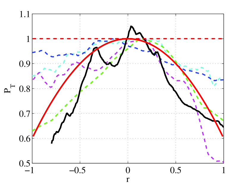
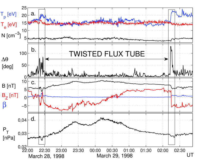
Figure 1 shows the radial structure of normalized total pressure (red solid line) inside the tube with simplest homogeneous twist of , where is a constant. It is seen that the total pressure is maximal at the tube axis and decreases towards the surface. Therefore, the variation of total pressure observed in situ by satellite may indicate the passage of an isolated twisted tube. Untwisted tube yields no variation in the total pressure (see red dashed line on Fig.1), therefore it is easy to identify the passage of twisted and untwisted tubes. The type of twist can be deduced from Eq. (1) using the observed profile of total pressure. In order to test the method, we consider already known observations of twisted magnetic flux tubes in the solar wind. WIND spacecraft magnetic field (Lepping et al., 1995) and plasma data (Lin et al., 1995; Ogilvie et al., 1995) are used. For demonstration purposes, Fig. 2 shows an event in detail, which was first spotted by Feng et al. (2007) and carefully analyzed by Telloni et al. (2012). It was found that this event was embedded between regions of different solar wind speed. The analysis of magnetic helicity and hodogram revealed a twisted structure with a clockwise rotation of the magnetic field within the structure (Telloni et al., 2012). The z-component of the magnetic field in GSE system also shows recognizable bipolar turning (Figure 2c), which according to Moldwin et al. (2000) is the classic flux rope signature (note that here is in the GSE system). The walls of the flux tube structure indicated by vertical boxes before 22:30 UT on March 28 (leading edge), 1998 and at 02:15 UT on March 29, 1998 (trailing edge) are readily recognizable as jumps in the values of physical quantities. At the trailing edge a sudden increase of and a slight decrease of can be observed with steady values afterwards. The temperature change, the increase of density and the single peaked jump in indicate that the probe crosses the flux tube discontinuity and enters to a different plasma. Contrarily, at the leading edge, the density before and after the wall is the same, one can see a simultaneous increase of both and and several rapid fluctuations in the orientation of magnetic field vector (). Since before and after the leading edge (first vertical box in Figure 2) the temperatures are smaller and fluctuates less, we interpret these observations as signatures of local heating at the unstable flux tube wall. We plot the total pressure () (Figure 2d), which is the sum of electron+proton thermal pressure and magnetic pressure. The enhanced at the center of the interval indicates a twisted magnetic field structure. Converting the temporal observations of the advected structures to spatial observations using the solar wind speed, we can compare our data with the theoretical total pressure profile for twisted flux tubes. The observed smoothed profile of total pressure (black solid line) is plotted over the theoretical profile of twisted tube (see Figure 1). It is seen that the theoretical curve describes the observed profile rather well. This means that the observed flux tube may have a homogeneous twist of . The double peaked structure, which is mainly resembling the evolution of (Figure 2c,d), can appear as a result of periodic kinking motions of the flux tube or internal inhomogeneities via turbulence or waves. In consequence of the kinking motion can gradually increase, then decrease, before the subsequent increase near the center of the flux tube. Since the changes are rather smooth in time with a quasi-period 1 h (Figure 2d) we can suppose that the resulting double peaked structure is associated with kink motions rather than multi-scale turbulence. The other curves of total pressure in Figure 1 correspond to WIND flux tube events, listed in Moldwin et al. (2000), for which both proton and electron data are available. These plots indicate that the total pressure has radial structure inside the flux ropes of Moldwin et al. (2000), therefore it is in agreement with our predictions. However, some flux tubes in Moldwin et al. (2000) are less twisted than the event in Figure 2.
The twist angle near the tube surface for the model pressure profile (red solid line on Fig. 1) is estimated as 550. Then the flux tube of Feng et al. (2007) and some tubes of Moldwin et al. (2000) are twisted with the angle of 500-550, while the other tubes of Moldwin et al. (2000) are less twisted.
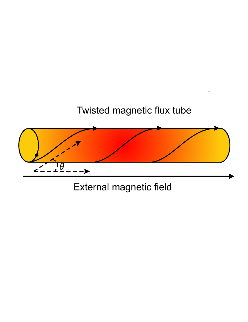
The abrupt change of magnetic field direction may indicate a crossing the wall of twisted tube if the axis of an isolated tube is aligned with the Parker spiral (Figure 3). Then the angle of abrupt change of magnetic field direction may show the twist angle at the tube wall, which could be significantly scattered from the direction of the Parker spiral. Indeed, in a statistical study, Borovsky (2008) found that the tube axes are aligned with the Parker spiral with significant scatter (Borovsky considered only untwisted tubes, therefore the direction of magnetic field inside the tube was considered as the tube axis). The observational scatter of tube magnetic field average direction with regards to the Parker spiral can be explained by the simultaneous existence of untwisted and twisted magnetic tubes in the solar wind plasma: untwisted tubes in average are aligned with the Parker spiral and the scatter is caused by the twisted tubes. However the hypothesis is too simplified and some spread in results is expected due to the complexity of solar wind plasma. Borovsky (2008) also found that the mean angle between the tube magnetic field and the Parker spiral is 42.70, while the mean angle between the wall normal and the Parker spiral is peaked towards 900. If the magnetic tube axes are aligned with the Parker spiral, then the result of Borovsky (2008) means that the mean twist angle of tubes is 42.70. On the other hand, the twisted tubes are subjects to the kink instability when the twist exceeds a critical value. Therefore it is important to estimate whether the angle is less than the critical one.
3 Stability of twisted magnetic flux tubes
Normal mode analysis (Dungey & Loughhead, 1954) and energy consideration method (Lundquist, 1951) show the similar thresholds of the kink instability in twisted magnetic tubes. The instability condition for the homogeneous twist and is . This leads to the critical twist angle of 650. Therefore, the mean twist angle of 42.70 indicates that the majority of tubes are stable to the kink instability. External magnetic field may increase the threshold and thus stabilize the instability (Bennett et al., 1999). On the other hand, a flow along the twisted magnetic tube may decrease the threshold (Zaqarashvili et al., 2010). Magnetic flux tubes in the solar wind may move with regards to the main stream of solar wind particles, therefore it is important to study the competitive effects of external magnetic field and the motion of tube (or external medium). Note that the consideration is simplified compared to turbulent solar wind plasma.
In order to study the instability criterion of moving twisted magnetic flux tube in the external magnetized medium, we use the normal mode analysis. We consider a tube with the homogeneous twist, , homogeneous axial magnetic field and uniform density . The external medium with homogeneous magnetic field directed along the -axis and the uniform density is moving with homogenous speed along the tube axis i.e. along the -axis. It is equivalent to the consideration of moving magnetic tube with the speed of in static external medium. In order to obtain the dispersion equation governing the dynamics of the tube, one should find solutions of perturbations inside and outside the tube and then merge them at the tube surface through boundary conditions. After Fourier analysis of linearized magnetohydrodynamic equations with , where is longitudinal wavenumber and is the frequency, incompressible perturbations of total pressure, , inside the tube are governed by the Bessel equation (Dungey & Loughhead, 1954; Bennett et al., 1999; Zaqarashvili et al., 2010; Zhelyazkov & Zaqarashvili, 2012)
| (2) |
where
The bounded solution of the equation is the modified Bessel function , where is a constant. The perturbations outside the tube is governed by the same Bessel equation, but is replaced by . The solution outside the tube bounded at infinity is , where is a constant. The boundary conditions at the tube surface are the continuity of Lagrangian displacement and total Lagrangian pressure (Dungey & Loughhead, 1954; Bennett et al., 1999; Zaqarashvili et al., 2010), which after straightforward calculations give the transcendental dispersion equation
| (3) |
where
and . A prime (′) denotes the derivative of a Bessel function to its dimensionless argument. Imaginary part of in the dispersion equation (Eq. 3) indicates the instability of the tube. The threshold for the kink instability () can be found analytically through the marginal stability analysis, i.e. considering (Chandrasekhar, 1961). Using the thin flux tube approximation, (yielding and ), after some algebra we obtain the following criterion for the kink instability from Eq. (3)
| (4) |
where is the Alfvén Mach number and (here is the relative speed of tube with regards to the mean solar wind stream and could be much less than the wind speed itself). For a static tube with a field-free environment the criterion leads to the Lundquist criterion (see also Dungey & Loughhead (1954)). For =0 it leads to the instability condition of twisted tube moving in a field free environment (Zaqarashvili et al., 2010). The critical twist angle for the kink instability can be approximated as
| (5) |
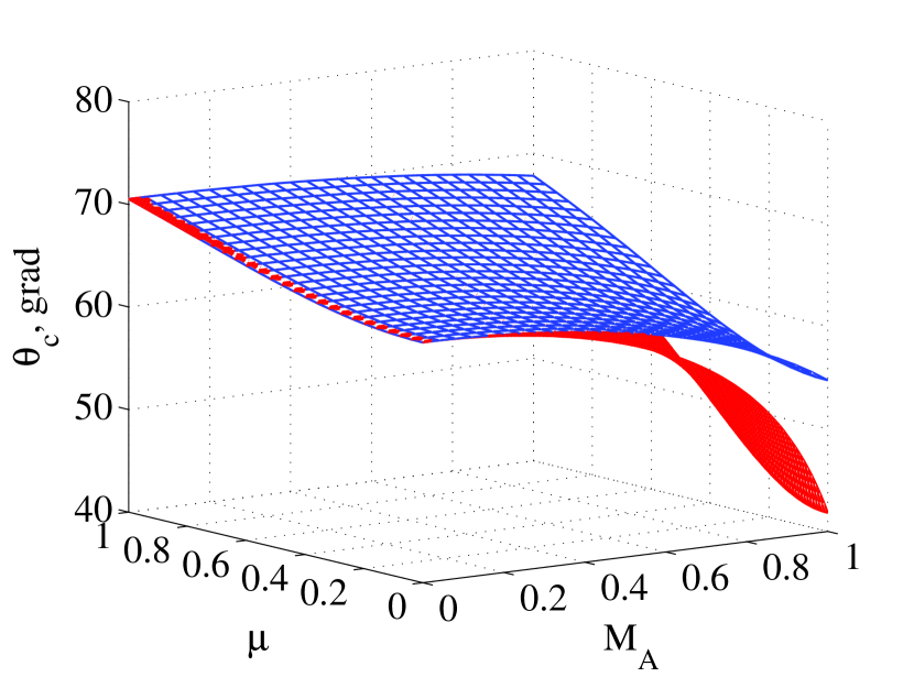
It is seen that the critical twist angle depends on the Alfvén Mach number, the ratio of external to internal axial magnetic field strength and the ratio of external to internal densities. The larger twist angle than the critical one leads to the kink instability. Figure 4 shows that the critical twist angle decreases when decreases and increases. More dense tubes are more stable. Maximum critical twist angle 700 occurs for static tubes and . It means that the tubes twisted with the angle of 700 are always unstable to the kink instability.
The kink instability may lead to the magnetic reconnection, which may either destroy the tube (Feng et al., 2011) or remove additional twist from the tube keeping only stable configuration. Therefore, the tubes twisted with the angle of 700 probably can not reach the distance of 1 AU. The motion of tube with the Alfvén speed with regards to the solar wind stream may reduce the critical twist angle to 450 for and =0.8 . This is close to the statistically mean value of the angle between tube magnetic field and the Parker spiral obtained by Borovsky (2008). Three from five tubes analyzed in this letter have the twist angle of 500-550, which is less than the critical angle for the kink instability of the tubes with , but can be larger for tubes with . Suppose a magnetic flux tube is twisted with sub-critical angle near the Sun. The Alfvén Mach number could be increased towards the Earth owing to the decrease of Alfvén speed. Consequently, initially stable flux tube may become unstable to the kink instability at some distance from the Sun. Two other tubes are below the threshold of kink instability for any .
4 Discussion and Conclusions
It is shown in this letter that the twisted magnetic tubes in the solar wind can be detected by in situ observations as variation of total pressure during the passage of the tubes through a satellite. The method allows us to obtain the radial structure of the twist and it can be used for any configuration of the magnetic field including non force-free field. We tested the method using several already known cases of observed twisted tubes, which shows that the total pressure in observed events resemble the theoretically expected profile. Therefore, the total pressure variation can be used to estimate the value of twist and its radial structure in the tubes embedded in the solar wind. The method can be also used to estimate the twist in coronal mass ejections (CME) in addition to Grad - Shafranov Reconstruction method (Möstl et al., 2009).
We suggest that the twist of isolated magnetic tube may explain the observed abrupt changes of magnetic field direction at tube walls in the solar wind (Borovsky, 2008). The mean statistical angle of the abrupt change, which was estimated by Borovsky (2008) as 42.70, can be considered as the mean twist angle of the magnetic flux tubes. Observed significant scatter of tube magnetic field average direction with regards to the Parker spiral can be explained by untwisted and twisted magnetic tubes: untwisted tubes are aligned with the Parker spiral and the scatter is caused by the twisted tubes.
Using stability analysis of twisted magnetic tubes, we obtain the theoretical criterion of kink instability, which shows that the maximal twist angle is 700 in the case of static tubes, while it decreases to 450 for the tubes moving with the Alfvén speed with regards to the solar wind. It may explain the observed mean statistical angle of 42.70, because the tubes twisted with a larger angle are unstable to the kink instability, therefore they probably can not reach 1 AU.
Tangential velocity discontinuity due to the motion of magnetic flux tubes with regards to the solar wind stream may lead to the Kelvin-Helmholtz instability (Drazin & Reid, 1981). A flow-aligned magnetic field may stabilize sub-Alfvénic flows (Chandrasekhar, 1961). However, the twisted tubes can be unstable for any sub-Alfvénic motions if they move with an angle to the Parker spiral (Zaqarashvili et al., 2014). Then the Kelvin-Helmholtz vortices may lead to the enhanced MHD turbulence and plasma heating near the walls of twisted magnetic tubes.
Statistical fraction of twisted tubes in the solar wind may correspond to the fraction of twisted tubes near the solar surface, which is not known because of observational constraints. Therefore, in situ observations of twisted tubes in the wind may allow us to estimate their percentage in the solar lower atmosphere.
In conclusion, twisted magnetic flux tubes could be essential components in the solar wind structure and they may play significant role in the turbulence and heating of the solar wind plasma.
Acknowledgements The work was supported by EU collaborative project STORM - 313038. The work of TZ was also supported by FP7-PEOPLE-2010-IRSES-269299 project- SOLSPANET, by Shota Rustaveli Foundation grant DI/14/6-310/12 and by the Austrian Fonds zur Förderung der wissenschaftlichen Forschung under project P26181-N27. The work of ZV was also supported by the Austrian Fonds zur Förderung der wissenschaftlichen Forschung under project P24740-N27. We acknowledge WIND spacecraft flux-gate magnetometer data from the Magnetic Field Investigation, plasma data from the 3D Plasma Analyser and from the Solar Wind Experiment.
References
- Archontis et al. (2004) Archontis, V., Moreno-Insertis, F., Galsgaard, K., Hood, A., and O’Shea, E., 2004, A&A, 426, 1047
- Bennett et al. (1999) Bennett, K., Roberts, B. and Narain, U., 1999, Sol. Phys., 185, 41
- Borovsky (2008) Borovsky, J. E., 2008, J. Geophys. Res., 113, A08110
- Brown et al. (2003) Brown, D. S., Nightingale, R. W., Alexander, D., Schrijver, C. J., Metcalf, T. R., Shine, R. A., Title, A. M., and Wolfson, C.J., 2003, Sol. Phys., 216, 79
- Bruno et al. (2001) Bruno, R., Carbone, V., Veltri, P., Pietropaolo, E. and Bavassano, B., 2001, Plan. Space Sci. 49, 1201
- Bruno et al. (2007) Bruno, R., D’Amicis, R., Bavassano, B., Carbone, V. and L. Sorriso-Valvo, 2007, Ann. Geophys. 25, 1913
- Cartwright and Moldwin (2010) Cartwright, M. L. and Moldwin, M. B., 2010, J. Geophys. Res., 115, A08102
- Chandrasekhar (1961) Chandrasekhar, S., 1961, Hydrodynamic and Hydromagnetic Stability (Oxford: Clarendon Press)
- Chang et al. (2004) Chang, T., Tam, S. and Wu, C., 2004, Phys. Plasmas, 11, 1287
- Drazin & Reid (1981) Drazin, P. G., and Reid, W. H., 1981, Hydrodynamic Stability (Cambridge: Cambridge University Press)
- Dungey & Loughhead (1954) Dungey, J. W. and Loughhead, R. E., 1954, Austr. J. Phys., 7, 5
- Feng et al. (2007) Feng, H. Q., Wu, D. J., and Chao, J. K., 2007, J. Geophys. Res., 112, A02102
- Feng et al. (2011) Feng, H. Q., Wu, D. J., Wang, J. M. and Chao, J. W., 2011, A&A, 527, A67
- Lepping et al. (1995) Lepping, R. P., Acuna, M. H., Burlaga, L. F. et al., 1995, Space Sci. Rev. 71, 207
- Li et al. (2012) Li, X., Morgan, H., Leonard, D. and Jeska, L., 2012, ApJ, 752, L22
- Lin et al. (1995) Lin, R. R., Anderson, K. A., Ashford, S. et al., 1995, Space Sci. Rev., 71, 125
- Lundquist (1951) Lundquist, S., 1951, Phys. Rev. 83, 307
- Malara et al. (1996) Malara, F., Veltri, P., and Carbone, V., 1996, J. Geophys. Res., 101, 21597
- Moldwin et al. (2000) Moldwin, M. B., Ford, S., Lepping, R., Slavin, J., and Szabo, A., Geophys. Res. L., 27, 57
- Moreno-Insertis & Emonet (1996) Moreno-Insertis, F. and Emonet, T., 1996, ApJ, 472, L53
- Möstl et al. (2009) Möstl, C., Farrugia, C. J., Biernat, H. K., Leitner, M., Kilpua, E. K. J., Galvin, A. B., Luhmann, J. G., 2009, Sol. Phys., 256, 427
- Ogilvie et al. (1995) Ogilvie, K. W., Chornay, D. J., Fritzenreiter, R. J. et al., 1995, Space Sci. Rev. 71, 55
- Osman et al. (2012) Osman, K., Matthaeus, W., Wan, M. and Rapazzo, A., 2012, Phys. Res. Lett., 108, 261102
- Servidio et al. (2009) Servidio, S., Matthaeus, W. H., Shay, M. A. , Cassak, P. A. and Dmitruk, P., 2009, Phys. Rev. Lett., 102, 115003
- Srivastava et al. (2010) Srivastava, A. K., Zaqarashvili, T. V., Kumar, P., and Khodachenko, M.L., 2010, ApJ, 715, 292
- Telloni et al. (2012) Telloni, D., Bruno, R., D’Amicis, R., Pietropaolo, E., and Carbone, V., 2012, ApJ, 751, 19
- Wedemeyer-Böhm et al. (2012) Wedemeyer-Böhm, S., Scullion, E., Steiner, O., Rouppe van der Voort, L., de La Cruz Rodriguez, J., Fedun, V., and Erdélyi, R., 2012, Nature, 486, 505
- Zaqarashvili et al. (2010) Zaqarashvili, T. V., Díaz, A. J., Oliver, R., and Ballester, J. L., 2010, A&A, 516, A84
- Zaqarashvili et al. (2014) Zaqarashvili, T. V., Vörös, Z. and Zhelyazkov, I., 2014, A&A, 561, A62
- Zhang et al. (2007) Zhang, J., Li, L., and Song, Q., 2012, ApJ, 662, L35
- Zhelyazkov & Zaqarashvili (2012) Zhelyazkov, I. and Zaqarashvili, T. V., 2012, A&A, 547, A14