Domain walls in two-dimensional nematics confined in a small circular cavity
Abstract
Using Monte Carlo simulation, we study a fluid of two-dimensional hard rods inside a small circular cavity bounded by a hard wall, from the dilute regime to the high-density, layering regime. Both planar and homeotropic anchoring of the nematic director can be induced at the walls through a free-energy penalty. The circular geometry creates frustration in the nematic phase and a polar-symmetry configuration with a distorted director field plus two disclinations is created. At higher densities, a quasi-uniform structure is observed with a (minimal) director distortion which is relaxed via the formation of orientational domain walls. This novel structure is not predicted by elasticity theory and is similar to the step-like structures observed in three-dimensional hybrid slit pores. We speculate that the formation of domain walls is a general mechanism to relax elastic stresses in conditions of strong surface anchoring and severe spatial confinement.
I Introduction
In adsorbed nematics, surfaces often determine the favoured director orientation, which then propagates into the bulk Jérôme (1991). When a nematic is subject to orientations propagating from different surfaces, elasticity theory predicts a distorted director configuration, with an associated elastic free energy. Very often conflicting surface orientations frustrate the director in restricted geometries and disclinations are generated. Disclinations can be generated by curvature alone Lubensky and Prost (1992), for example by placing a two-dimensional (2D) nematic on a finite but unbounded surface such as a spherical surface Shin et al. (2008); Zhang et al. (2012); Dzubiella et al. (2000). The dimensionality of space is also important since it forces the possible topology and limits the type of defects that can form.
Consider a 2D nematic made of rod-like particles inside a small (of a size a few times the particle length) circular cavity. When the density is increased from a dilute state, the bulk isotropic-nematic transition Cuesta and Frenkel (1990); Bates and Frenkel (2000); de las Heras et al. (2013); Isa et al. (2011) induces some kind of orientational ordering in the cavity. However, due to the surface, the nematic director is unable to adopt a defect-free uniform configuration, and a global topological charge Nelson (2002) arises in the cavity: either as a central disclination, or as two diametrically opposed disclinations (on the surface or at a distance from it). Thus the fluid optimises the surface free energy at the cost of creating two disclinations and a distorted director field (which incurs an elastic free energy). This effect has been observed in Monte Carlo (MC) simulations Dzubiella et al. (2000). For weak surface anchoring there is an alternative scenario: the director may not follow the favoured surface orientation and a quasi-uniform, defect-free configuration with little elastic free energy may arise in the cavity. A uniform phase has been obtained in vibrated monolayers of granular rods Galanis et al. (2010). Interesting phase diagrams result as the cavity radius and the fluid density are changed, as exemplified by recent density-functional calculations de las Heras et al. (2009a, b); Chen (2013).
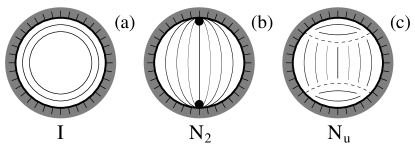
In this paper we use Monte Carlo simulation to analyse this system, using hard rectangles of length-to-width ratio as a particle model and a circular cavity of radius that imposes hard or overlap forces on the particles. Both planar (tangential) and homeotropic (normal) anchorings are studied. In both cases we observe the formation of 1D domain walls when the cavity radius is small. The scenario is schematically depicted in Fig. 1 (for the sake of illustration, only the planar case is depicted): an isotropic phase, I, at low density (containing a thin nematic film in contact with the wall), Fig. 1(a), followed, at higher densities, by a nematic phase with two disclinations called polar configuration, N2, see Fig. 1(b). When the density increases further the polar configuration is no longer stable, and may transform into a structure with a quasi-uniform director configuration, phase Nu in Fig. 1(c). Depending on the surface conditions, cavity radius and particle aspect ratio, the Nu phase may be preempted by formation of layered (smectic-like) structures.
Our study contains two novel features. (i) In contrast with previous works, which focus solely on the nematic phase and the configuration of disclinations, the whole density range, from dilute to near close-packing, is explored here. (ii) The peculiar structure of the Nu phase: the incorrect surface alignment associated with a uniform director is here observed to be relaxed by the formation of domain walls, i.e. one-dimensional interfaces across which the director rotates abruptly by approximately ; this is represented by the dashed lines in Fig. 1(c). These structures are similar to the step-like defects observed in three-dimensional nematics inside hybrid planar slit pores Palffy-muhoray et al. (1994); Galabova et al. (1997); Šarlah and Žumer (1999); de las Heras et al. (2009c); Teixeira et al. (2009); Marguta et al. (2011) or near half-integer disclinations in cylindrical pores Schopohl and Sluckin (1987), and may be a universal feature in nematics subject to high frustration and strong anchoring under conditions of severe confinement. In our results, planar and homeotropic anchoring conditions behave similarly except for trivial but important differences. Although the calculation of a complete phase diagram including cavity radius, density and particle aspect ratio is beyond our present capabilities, we give general trends as to how the equilibrium phase depends on these parameters.
Our theoretical work is mainly inspired by recent experiments on vibrated quasi-monolayers made of granular rods that interact through approximately overlap forces (hard interactions). Nematic ordering is observed in these fluids Narayan et al. (2006, 2007); Galanis et al. (2010); Aranson and Tsimring (2006); Borzsonyi and Stannarius (2013). Granular materials are non-thermal fluids and therefore do not follow equilibrium statistical mechanics. In particular, they flow and diffuse anomalously Aranson et al. (2007); Yadav and Kudrolli (2012). However, they can also form steady-state textures that resemble liquid-crystalline states. In this context, it would be interesting to check whether MC simulation on hard particle models can be useful to obtain basic trends as to type of patterns, dependence with packing fraction and size of confining cavity, etc. The arrangement of rods in a 2D confining cavity has also been investigated in connection with the modelling of actin filaments in the cell cytoplasm Soares e Silva et al. (2011). Self-organised patterns of these filaments have been observed in various quasi-2D geometries and result from the combined packing and geometrical constraints. Simulation studies such as the present one could also provide mechanisms to explain this and other experiments on confined quasi-two-dimensional nematics Mottram and Sluckin (2000).
II Model and simulation method
The particle model we use is the hard-rectangle (HR) model, consisting of particles of length-to-width ratio or that interact through overlap interactions. The configuration of a particle is defined by , respectively the position vector of the centre of the particle and the unit vector giving the orientation of the long particle axis. A collection of such particles is placed in a circular cavity of radius . We define the packing fraction of the system as the ratio of area covered by rectangles and total area of the cavity. Thus , where is the mean density.
For such large length-to-width ratios a fluid of HR undergoes a phase transition from an I phase to a nematic (N) at rather low densities Schlacken et al. (1998); Martínez-Ratón et al. (2005); de las Heras et al. (2007); Martínez-Ratón and Velasco (2009); Martínez-Ratón et al. (2006); Geng and Selinger (2009). The bulk transition is continuous and probably of the Kosterlitz-Thouless type; this detail is irrelevant here since, due to the completely confined geometry, there can be no true phase transition in the circular cavity and one expects a possibly abrupt but in any case gradual change from the I phase to the N phase.
The effect of the cavity wall on the particles is represented via an external potential . In all cases this is a hard potential but, depending on the type of surface anchoring condition wished (either homeotropic or planar), the potential can be chosen to act on the particle centres of mass or on the whole particle –all four corners of the particle. Specifically,
| (8) |
where , with Boltzmann’s constant and the temperature. A hard wall acting on the whole particle promotes planar ordering. However, if the condition is on the particle centers of mass, it is homeotropic anchoring that is promoted. This was shown by MC Dzubiella et al. (2000) and density-functional studies de las Heras et al. (2009a), and has also been confirmed in fluids of hard discorectangles confined in 2D circular cavities or in fluids of rods confined in slit pores in 3D Allen (1999); de las Heras et al. (2004); Reich and Schmidt (2007). Since a single particle close to a wall may have any orientation in this type of condition, one infers that homeotropic anchoring results from the collective effect of all particles. By contrast, a hard wall over the whole particle induces planar anchoring. In this case anchoring is not the result of a collective effect since a single particle sufficiently close to the wall is forced to adopt an orientation parallel to the wall.
The simulation method was the following. We started at low density with a few particles inside the cavity. After equilibrating the system using the standard Metropolis algorithm on particle positions and orientations, a few particles are added and the fluid is equilibrated again. The number of particles added varied between and , resulting in an increase in packing fraction of (depending on aspect ratio and cavity radius). This process was repeated until a high density was reached.
For the insertion process we first chose one particle at random and create a replica with the same orientation but with the long axis displaced by . Then we performed a few thousands rotations and displacements on the new particle. The addition of one particle, especially when the density is high, may lead to overlap; in that case we chose another particle to create the replica and a new attempt was made until insertion was completed successfully. The simulation ended when the desired density was reached or if the addition of new particles is no longer possible. As usual, a Monte Carlo step (MCS) is defined as an attempt to individually move and rotate all particles in the system. We performed MCS for each . The acceptance probability was set to about , and depended on the maximum displacement and maximum rotation each particle is allowed to perform in one MCS. Both, and , are adjusted to obtain the desired acceptance probability every time we increase the number of particles.
To characterise the fluid structure in the cavity, three local fields are defined: (i) A local density in terms of a local packing fraction ; here is the position vector of a particle centre of mass. (ii) A local order tensor , defined as , where denotes a canonical average, is the unit vector pointing along the particle axis, and is the angle with respect to the axis. The order tensor can be diagonalised, and the largest eigenvalue is taken as the local order parameter (the other eigenvalue is negative and with the same absolute value). The axis of the frame where is diagonal defines a local tilt angle with respect to the laboratory-frame axis.
All local quantities, , and were defined, at each , as an average of each quantity for all particles over a circle of radius and for different configurations separated by MCS (all local fields shown in this paper were obtained in this way). This number of configurations is necessary in order to obtain spatially smooth fields. However, a complication may arise due to the collective rotation of the particles inside the cavity. As the cavity does not impose a global director, microstates with the same average order parameter but distinct global directors are equivalent. Hence, an ensemble average over these states can artificially result in a state with lower order parameter. In particular, the collective rotations of the particles take place more frequently at low packing fractions, hindering the nematization analysis. Since the precise location of the transition to the nematic state is not the goal of our work, we did not attempt to address this problem.
As shown in section III, distinct states characterised by different local nematic fields will arise in the cavity as the density is increased. Given the completely restricted geometry and the reduced number of particles in the cavity, abrupt changes are not expected and only a continuous transition between the different states can occur in the system. In order to check this, we have run simulations for selected cavity radii by first increasing and then decreasing the number of particles, looking for possible hysteresis effects. As expected, no such effects were found in the process and we can be confident that the states described in the following section are the stable ones.
III Results
An overall picture of the phenomena occurring in the cavity as the density is increased can be obtained by looking at typical particle configurations, local packing fraction and local order parameter. In this section we first present the results for the planar case, and then for the homeotropic case. In both cases cavity radii from to were explored, all for and .
III.1 Planar anchoring
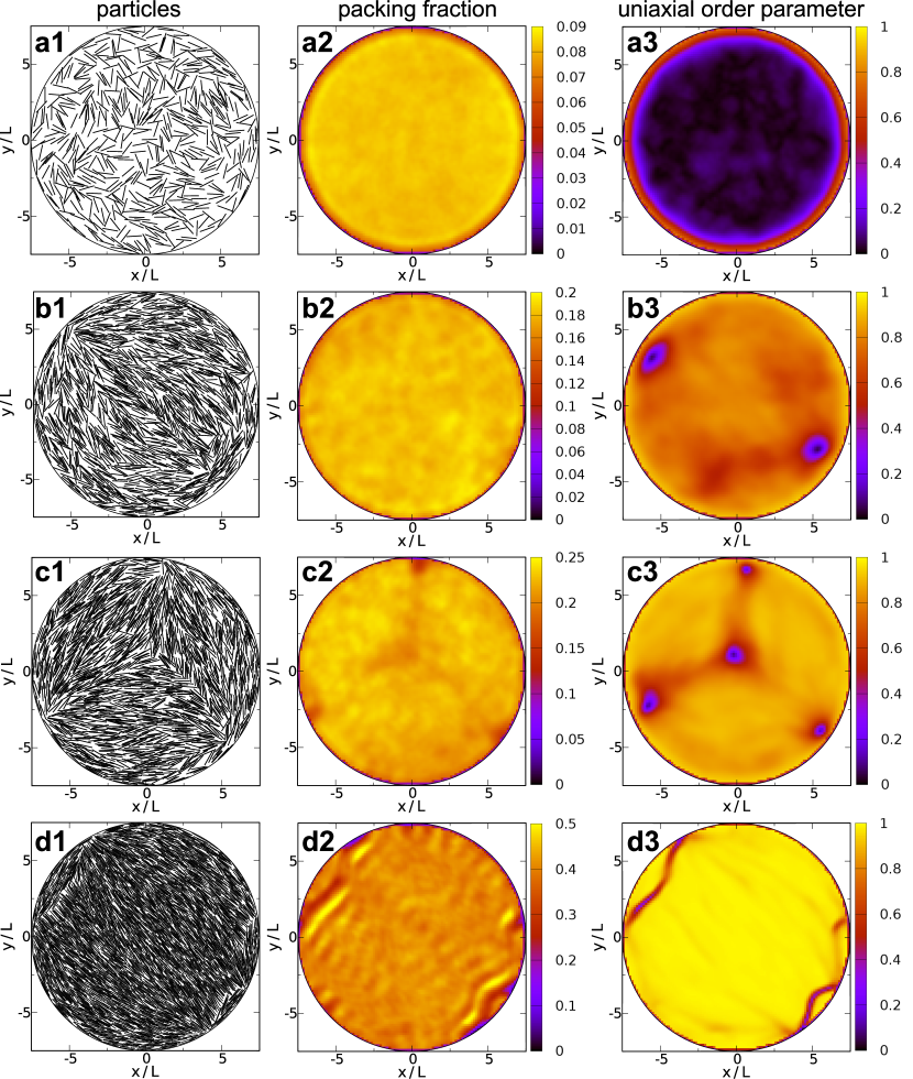
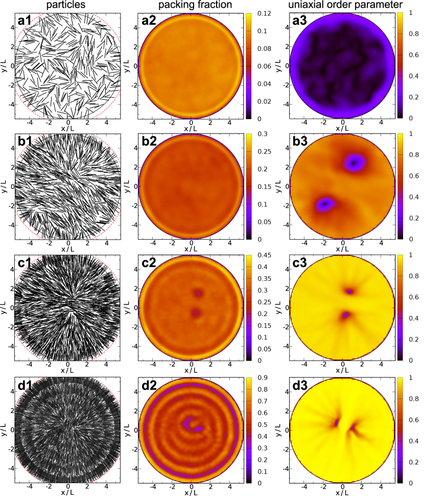
Representative results in the case of planar anchoring can be obtained from the case and (the behaviour is qualitatively the same for the other cavity radii and aspect ratios analysed). The initial number of particles was (corresponding to a packing fraction ), and the final number of particles was (). The results are shown in Fig. 2, where each row corresponds to a given packing fraction, increasing from top to bottom.
At low (first row in Fig. 2) the fluid is disordered (I phase), except at a thin film next to the wall which presents some degree of planar ordering. As the fluid becomes more dense it undergoes a quasi-transition from the I phase to the N2 phase at a density close to the bulk transition (the second row in the figure, for , corresponds to a nematic state, i.e. beyond the bulk transition). This density agrees closely with that predicted for hard rods in 2D Bates and Frenkel (2000); Martínez-Ratón et al. (2005). Nematization in the case is qualitatively similar, except that the transition density is more or less doubled.
Once a nematic fluid is established in the cavity, the local director is subject to frustration due to the geometry. The planar surface orientation is satisfied by the particles but, due to the topological restrictions imposed by the wall, the nematic fluid creates two disclinations of topological charge next to the walls in diametrically opposed regions. This feature manifests itself in panel b3 through the depleted order parameter at the disclination cores (by contrast, the local , panel b2, is not sensitive because the ordered and disordered phases have the same density). Two isolated disclinations are always more stable than a single point defect of charge because the free energy is proportional to the square of the topological charge. The boundaries could modify this balance, but our results, already predicted by density-functional calculations de las Heras et al. (2009a), indicate that this is not the case.
Sometimes along the MC chain, configurations with two extra disclinations are excited (third row in Fig. 2): one of charge , close to the surface and forming an equilateral triangle with the previous two, and another one with charge at the centre (panel c3); these configurations, which still have a total topological charge of , do not appear very often in the MC chain since they involve a higher elastic free energy, and anyway the and disclinations tend to annihilate each other. A similar metastable configuration has been observed in simulations of hard spherocylinders lying on the surface of a three-dimensional sphere Dzubiella et al. (2000).
At higher densities a dramatic structural change can be observed (fourth row in Fig. 2). As increases,
elastic stresses becomes very large because of the strong dependence of elastic constants, , with density.
As a consequence, a quasi-uniform director configuration (Nu phase) with little elastic stress is formed
beyond some critical value .
The director orientation is not completely uniform. A perfectly uniform director configuration would imply that the
planar orientation favoured at the wall is not completely satisfied. However, the fluid can reduce the increased
surface free-energy implied by a strictly uniform director field by creating two fluctuating domain walls, panel d3,
that define two diametrically opposed domains where the director rotates by . Alternatively, we can view this
structure as a polar structure (stable at lower densities) where the two point defects are smeared out into a curved
one-dimensional interface. Particles in the two small domains satisfy the surface orientation. Note that the domain walls
behave as a soft wall: particles of the central domain next to the interface are highly ordered and the density in these
regions is increased (panel d2). Domain walls are seen to behave as highly fluctuating structures.
The value of packing fraction, , at which the N2-Nu transition takes place increases with cavity radius . To understand this, let us consider the free energy of both configurations, N2 and Nu, with respect to an undistorted nematic state with free energy . Three terms contribute to the excess free-energy : domain walls, , elastic deformations of the director field, , and disclination cores, . In the N2 state the director field is distorted; the free energy presents a logarithmic dependence with , i.e. De Gennes and Prost (1995); Kléman and Lavrentovich (2002), while the contribution from the two disclinations is almost constant (assuming the distance between the cores to be independent of ). In the Nu state director deformations are negligible in comparison to the other phase, but the presence of domain walls increases the free energy. Since is proportional to the length of the domain wall, it should also increase with , but faster than . Due to the weaker dependence of with , we expect a transition from Nu to N2 when is increased beyond some critical value and consequently should be an increasing function of in view of the density dependence of the elastic constants . This conclusion is confirmed by our simulations (not shown).
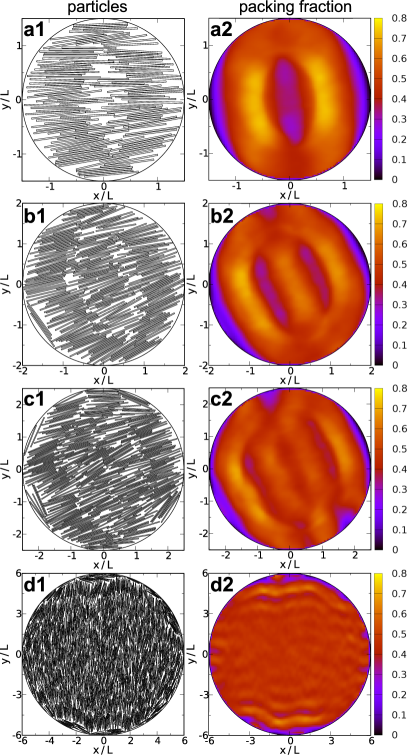
On further increasing the value of , the fluid may develop smectic-like layers, reflecting the corresponding transition in bulk. The role played by cavity radius is especially important in this regime. To see this, we plot in Fig. 3 representative snapshots of the particle configurations (left column) and the local packing fraction (right column) of particles with aspect ratio . In all cases the average packing fraction is (well above the bulk I-N transition) and the radius increases from top to bottom: , , and . As expected, strong commensuration effects arise in the cavity at high density. For small cavity radii, the particles form well defined layers (first three rows in figure), the number of which depends on the available space. The formation of layers inside the cavity is the analogue of capillary smectization of a liquid crystal in slab geometry previously analysed in 3D de las Heras et al. (2005, 2006); Xu et al. (2008); Malijevský and Varga (2010) and 2D Martínez-Ratón (2007). In general, the circular shape of the cavity frustrates the formation of well-defined layers, but the combined effect of shape and size may frustrate or enhance the formation of layers. In this system small cavity sizes promote layering: in the cases shown, the fluid remains in a nematic-like N state when (see panels d1 and d2 of Fig. 3), but for smaller cavities at the same packing fraction well defined smectic-like layers can develop.
III.2 Homeotropic anchoring
In this case the wall acts as a hard wall on the particle centres of mass. In order to be able to compare with the planar case, we define an effective cavity radius, , and obtain an effective packing fraction as . In contrast with the planar case, for homeotropic anchoring we observe strong differences with respect to particle aspect ratio for a fixed cavity radius: the Nu phase is stabilised for , but the N2–Nu transition is preempted by the formation of smectic-like layers when and, as a result, no quasi-uniform configuration occurs.
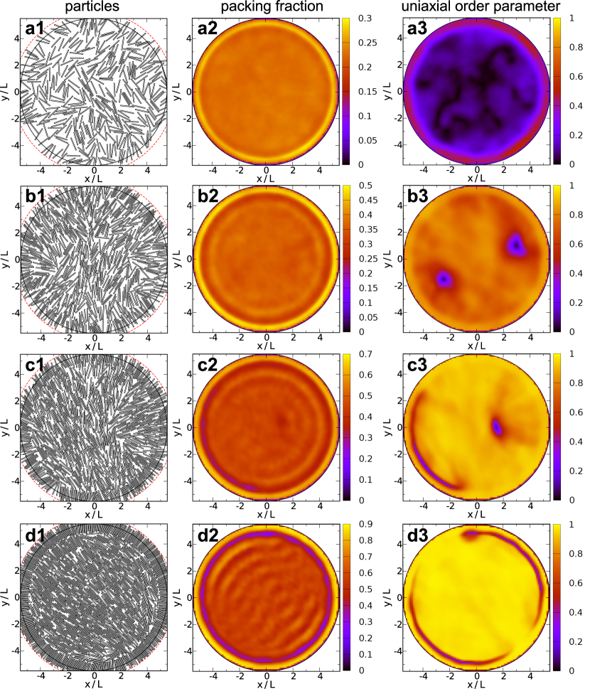
Fig. 4 summarises a typical evolution of the configurations as is increased when . The low-density configuration (first row) is similar to the planar case: a thin (one-particle thick) film develops at the wall, now with normal average orientation of the particles, while the rest is disordered.
When the density increases and nematic order appears in the whole cavity (second row of Fig. 4), the topological constraints force the creation of two disclinations of charge ; this is as in the planar case (second row of Fig. 2). Here the two defects are not at the wall but a bit separated. This feature was predicted by density-functional theory de las Heras et al. (2009a, b) and results from the effective repulsion of the defect by the wall combined with the mutual repulsion between the two defects (in the planar case such defect-wall repulsion does not exist). As the density is increased further the two disclinations can be seen to approach each other (not shown). This behaviour is in contrast with that predicted by the Onsager-like theory analysed in de las Heras et al. (2009a), according to which the relative distance should increase with chemical potential (or, equivalently, density). Again two effects are at work as density increases: defect-wall repulsion, which increases due to the strong spatial ordering near the wall and the incipient stratification from the wall in the normal direction (panels b2), and defect mutual repulsion, which also increases due to the higher elastic stiffness of the nematic. The poor description of strong density modulations occurring at high density in Onsager theory may explain the discrepancy.
The third row in Fig. 4, corresponding to a larger value of packing fraction, represents an intermediate (probably metastable) stage between the polar state and what appears to be the stable configuration at high density: the uniform phase, Nu (fourth row). Here the director alignment in the cavity is more or less uniform, with little bend-like elastic distortion. However particles in the first layer, highly packed in a compact normal configuration, form a well defined and stable film acting as a soft wall favouring planar orientation. This results in a quasi-uniform phase Nu, similar to that found in the case of planar anchoring at high densities. The resulting configuration contains two extended domain walls separating the first layer from the central nematic domain. The NNu transition is driven by an anchoring-transition mechanism: the orientation of particles next to the first layer changes from normal (see panel b1 in Fig.4) to tangential (panel d1) along opposite arcs spanning ; note that in the configuration of panel c1 the transition has taken place only in one side. As in the N2 phase, the formation of these domain walls breaks rotational symmetry and establishes a direction along which smectic-like layers can grow at higher densities (see incipient layering in panel d2).
The stability of the Nu phase was checked by preparing a configuration of rods in a cavity of radius containing a central radial disclination of charge . During the MC chain the system rapidly formed a polar phase with two disclinations, similar to that depicted in Fig. 4 (b1). Then an anchoring transition took place in half of the cavity, and finally the Nu phase was stabilised and remained unchanged for the rest of the simulation. This can be taken as strong evidence that the Nu phase is the truly stable phase.
For particle aspect ratio and the same cavity radius, Fig. 5, low-density states are similar to those with aspect ratio (first and second row of Fig. 4). However, the order parameter close to the surface is significantly lower than in the case of planar anchoring (compare panels a3 of Figs. 2 and 5). The reason is the following: A single particle at close contact with the wall has a specific (tangential) alignment when the wall acts over the whole particle; out-of-tangential alignments lead to particle-wall overlap and are not allowed, which increases the order parameter. In contrast, a hard wall acting on the centers of mass does not induce any favoured orientation on the particles if the density is sufficiently low.
As increases a nematization transition occurs, and a N2 phase is stabilised at intermediate densities. However, for larger densities, the situation changes dramatically: the homeotropic anchoring imposed by the surfaces always propagates to the inner cavity since the locking mechanism that anchors particles to the first layer is much more effective: the normal-to-tangential anchoring transition never takes place. At higher packing fractions, (fourth row in Fig. 4), a density stratification grows from the surface and particles form well-defined, concentric layers, the two disclinations being pushed to the central region. The size of the defect cores (regions where the order parameter vanishes) becomes significantly smaller as density is increased. Therefore, the absence of the anchoring transition inhibits the formation of the Nu phase and the fluid instead goes directly to a smectic-like phase exhibiting concentric layers.
Thus, for , the high-density states are completely different depending on the aspect ratio. Anchoring is much stronger in the case , the anchoring transition does not take place, and the quasi-uniform configuration is inhibited as a result. At high densities, smectic-like layers do not grow along a fixed direction but in the radial direction instead.
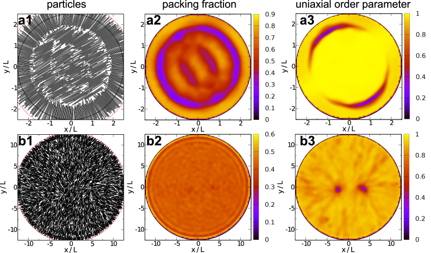
From this evidence, it may seem that the value of aspect ratio determines the type of structure in the cavity as increases. This is not the case, and in fact the ratio is a more important factor. To check this, we have conducted simulations for both elongations but with very different cavity sizes, for and for , Fig. 6. In the first case a uniform configuration with domain walls is stabilised; in the second, no anchoring transition occurs and, as a consequence, the Nu phase is not stabilised before layering sets in. We conclude that a large value of favours anchoring and inhibits the anchoring transition and the formation of the quasi-uniform phase. In turn, the critical value of the ratio separating both regimes depends on to some extent.
IV Discussion and conclusions
In summary, we have observed the formation of domain walls in 2D nematic fluids subject to frustration as a result of confinement in small cavities. These structures, not predicted by elasticity theory, are similar to the step-like defects obtained in model 3D nematics confined in hybrid planar slit pores. At domain walls the director orientation changes at the molecular scale, so that the elastic field becomes singular along extended interfaces (lines in 2D or surfaces in 3D). In this way the elastic distortion is greatly relaxed, while the surface orientation is still optimised. Domain walls were predicted in an analysis of the neighbourhood of half-integer nematic disclinations, using Landau-de Gennes theory Schopohl and Sluckin (1987). In this case the domain wall is a way to avoid a disordered defect core. In hybrid planar slit pores, where the two facing surfaces favour antagonistic directions, a domain-wall structure has also been predicted by Landau-de Gennes theory Palffy-muhoray et al. (1994) and by density-functional calculations de las Heras et al. (2009c).
Here we have extended the observation of these domain walls to real particle simulations of confined nematics in 2D. In our system and for a fixed cavity radius, we have found the sequence INNu for increasing packing fraction . The packing fraction at which the NNu transition occurs strongly depends on cavity radius . At high density smectic-like layers are formed in the fluid. The Nu phase is a quasi-uniform phase with little director distortion; this is realised by the creation of two domain walls which help maintain the favoured surface orientation in the whole cavity. Homeotropic anchoring conditions induce the formation of a highly-packed surface film, which may drive an anchoring transition to a tangential orientation and the formation of a large quasi-uniform nematic domain separated from the first layer by domain walls. Large ratios inhibit the anchoring transition and therefore the stabilisation of the Nu phase, but the critical value of depends on the aspect ratio . Our results emphasise the possibility of domain-wall formation in small confined systems as a mechanism to optimise surface and elastic stresses.
It is interesting to compare our results with other studies. Dzubiella et al. Dzubiella et al. (2000) analysed a similar system using MC simulation. They focused on moderate densities and obtained the N2 phase. Galanis et al. Galanis et al. (2010) studied vibrated quasi-monolayers of rods in circular and square geometries, and observed the formation of nematic patterns. The patterns were seen to be well described by continuum elastic theory, but the particle configurations of the experiment seem to exhibit some evidence of domain walls not contemplated in that work. The formation of two disclinations has been also predicted in active matter confined in cylindrical capillaries Ravnik and Yeomans (2013) and circular cavities Woodhouse and Goldstein (2012).
Recently, liquid-crystalline ordering has been studied in square cavities using density-functional González-Pinto et al. (2013) and MC simulation Geigenfeind et al. (2013). Domain walls can be stabilised in these systems. For some geometries the formation of domain walls may be a necessary requirement for the development of confined phases with spatial order (smectic or columnar) at higher densities.
V Acknowledgments
We thank M. Schmidt, T. Geigenfeind, S. Rosenzweig and Y. Martínez-Ratón for useful discussions and comments. E. V. acknowledges financial support from Programme MODELICO-CM/S2009ESP-1691 (Comunidad Autónoma de Madrid, Spain), and FIS2010-22047-C01 (MINECO, Spain).
References
- Jérôme (1991) B. Jérôme, Rep. Prog. Phys. 54, 391 (1991).
- Lubensky and Prost (1992) T. Lubensky and J. Prost, J. Phys. II 2, 371 (1992).
- Shin et al. (2008) H. Shin, M. J. Bowick, and X. Xing, Phys. Rev. Lett. 101, 037802 (2008).
- Zhang et al. (2012) W.-Y. Zhang, Y. Jiang, and J. Z. Y. Chen, Phys. Rev. Lett. 108, 057801 (2012).
- Dzubiella et al. (2000) J. Dzubiella, M. Schmidt, and H. Löwen, Phys. Rev. E 62, 5081 (2000).
- Cuesta and Frenkel (1990) J. A. Cuesta and D. Frenkel, Phys. Rev. A 42, 2126 (1990).
- Bates and Frenkel (2000) M. A. Bates and D. Frenkel, J. Chem. Phys. 112, 10034 (2000).
- de las Heras et al. (2013) D. de las Heras, Y. Martínez-Ratón, L. Mederos, and E. Velasco, J. Mol. Liq. 185, 13 (2013).
- Isa et al. (2011) L. Isa, J.-M. Jung, and R. Mezzenga, Soft Matter 7, 8127 (2011).
- Nelson (2002) D. R. Nelson, Defects and geometry in condensed matter physics (Cambridge University Press, 2002).
- Galanis et al. (2010) J. Galanis, R. Nossal, W. Losert, and D. Harries, Phys. Rev. Lett. 105, 168001 (2010).
- de las Heras et al. (2009a) D. de las Heras, E. Velasco, and L. Mederos, Phys. Rev. E 79, 061703 (2009a).
- de las Heras et al. (2009b) D. de las Heras, L. Mederos, and E. Velasco, Liq. Cryst. 37, 45 (2009b).
- Chen (2013) J. Z. Y. Chen, Soft Matter (2013).
- Palffy-muhoray et al. (1994) P. Palffy-muhoray, E. C. Gartland, and J. R. Kelly, Liq. Cryst. 16, 713 (1994).
- Galabova et al. (1997) H. G. Galabova, N. Kothekar, and D. W. Allender, Liq. Cryst. 23, 803 (1997).
- Šarlah and Žumer (1999) A. Šarlah and S. Žumer, Phys. Rev. E 60, 1821 (1999).
- de las Heras et al. (2009c) D. de las Heras, L. Mederos, and E. Velasco, Phys. Rev. E 79, 011712 (2009c).
- Teixeira et al. (2009) P. I. C. Teixeira, F. Barmes, C. Anquetil-Deck, and D. J. Cleaver, Phys. Rev. E 79, 011709 (2009).
- Marguta et al. (2011) R. G. Marguta, Y. Martínez-Ratón, N. G. Almarza, and E. Velasco, Phys. Rev. E 83, 041701 (2011).
- Schopohl and Sluckin (1987) N. Schopohl and T. J. Sluckin, Phys. Rev. Lett. 59, 2582 (1987).
- Narayan et al. (2006) V. Narayan, N. Menon, and S. Ramaswamy, J. Stat. Mech-Theory E. 2006, P01005 (2006).
- Narayan et al. (2007) V. Narayan, S. Ramaswamy, and N. Menon, Science 317, 105 (2007).
- Aranson and Tsimring (2006) I. S. Aranson and L. S. Tsimring, Rev. Mod. Phys. 78, 641 (2006).
- Borzsonyi and Stannarius (2013) T. Borzsonyi and R. Stannarius, Soft Matter 9, 7401 (2013).
- Aranson et al. (2007) I. S. Aranson, D. Volfson, and L. S. Tsimring, Phys. Rev. E 75, 051301 (2007).
- Yadav and Kudrolli (2012) V. Yadav and A. Kudrolli, Eur. Phys. J. E 35, 1 (2012).
- Soares e Silva et al. (2011) M. Soares e Silva, J. Alvarado, J. Nguyen, N. Georgoulia, B. M. Mulder, and G. H. Koenderink, Soft Matter 7, 10631 (2011).
- Mottram and Sluckin (2000) N. J. Mottram and T. J. Sluckin, Liq. Cryst. 27, 1301 (2000).
- Schlacken et al. (1998) H. Schlacken, H.-J. Mogel, and P. Schiller, Mol. Phys. 93, 777 (1998).
- Martínez-Ratón et al. (2005) Y. Martínez-Ratón, E. Velasco, and L. Mederos, J. Chem. Phys. 122, 064903 (pages 8) (2005),
- de las Heras et al. (2007) D. de las Heras, Y. Martínez-Ratón, and E. Velasco, Phys. Rev. E 76, 031704 (2007).
- Martínez-Ratón and Velasco (2009) Y. Martínez-Ratón and E. Velasco, Phys. Rev. E 79, 011711 (2009).
- Martínez-Ratón et al. (2006) Y. Martínez-Ratón, E. Velasco, and L. Mederos, J. Chem. Phys. 125, 014501 (2006).
- Geng and Selinger (2009) J. Geng and J. V. Selinger, Phys. Rev. E 80, 011707 (2009).
- Allen (1999) M. P. Allen, Mol. Phys. 96 (1999).
- de las Heras et al. (2004) D. de las Heras, E. Velasco, and L. Mederos, J. Chem. Phys. 120, 4949 (2004).
- Reich and Schmidt (2007) H. Reich and M. Schmidt, J. Phys-Condens. Mat. 19, 326103 (2007).
- De Gennes and Prost (1995) P. De Gennes and J. Prost, The Physics of Liquid Crystals. (Oxford University Press, 1995).
- Kléman and Lavrentovich (2002) M. Kléman and O. D. Lavrentovich, Soft matter physics: an introduction (Springer, 2002).
- de las Heras et al. (2005) D. de las Heras, E. Velasco, and L. Mederos, Phys. Rev. Lett. 94, 017801 (2005).
- de las Heras et al. (2006) D. de las Heras, E. Velasco, and L. Mederos, Phys. Rev. E 74, 011709 (2006).
- Xu et al. (2008) X. Xu, D. Cao, and W. Wang, J. Phys-Condens. Mat. 20, 425221 (2008).
- Malijevský and Varga (2010) A. Malijevský and S. Varga, J. Phys-Condens. Mat. 22, 175002 (2010).
- Martínez-Ratón (2007) Y. Martínez-Ratón, Phys. Rev. E 75, 051708 (2007).
- Ravnik and Yeomans (2013) M. Ravnik and J. M. Yeomans, Phys. Rev. Lett. 110, 026001 (2013).
- Woodhouse and Goldstein (2012) F. G. Woodhouse and R. E. Goldstein, Phys. Rev. Lett. 109, 168105 (2012).
- González-Pinto et al. (2013) M. González-Pinto, Y. Martínez-Ratón, and E. Velasco, Phys. Rev. E 88, 032506 (2013).
- Geigenfeind et al. (2013) T. Geigenfeind, S. Rosenzweig, M. Schmidt, and D. de las Heras, Unpublished (2013).