Optimisation of microstructured waveguides in z-cut LiNbO3 crystals
Abstract
We present a practical approach to the numerical optimisation of the guiding properties of buried microstructured waveguides, which can be fabricated in a -cut lithium niobate (LiNbO3) crystal by the method of direct femtosecond laser inscription. We demonstrate the possibility to extend the spectral range of low-loss operation of the waveguide into the mid-infrared region beyond .
1Aston Institute of Photonic Technologies, School of Engineering and Applied
Science,
Aston University, Birmingham B4 7ET, United Kingdom
2State Technical University, 77 Politekhnicheskaya str., 410054,
Saratov, Russia
\email∗m.dubov@aston.ac.uk
(190.4390) Nonlinear optics, integrated optics; (220.4000) Microstructure fabrication; (230.7370) Waveguides; (130.5296) Photonic crystal waveguides; (000.4430) Numerical approximation and analysis.
References
- [1] R. Osellame, G. Cerullo, and R. Ramponi, eds., Femtosecond Laser Micromachining: Photonic and Microfluidic Devices in Transparent Materials, Topics Appl. Phys. 123 (Springer-Verlag, 2012).
- [2] T. Suhara and M. Fujimura, Waveguide Nonlinear-Optic Devices (Springer Series in Phtonics) (Springer, 2003).
- [3] A. M. Streltsov, “Femtosecond-laser writing of tracks with depressed refractive index in crystals,” in Conference on Laser Micromachining for Optoelectronic Device Fabrication, A. Ostendorf, ed., Proc. SPIE 4941, 51- 57 (2003).
- [4] A. G. Okhrimchuk, A. V. Shestakov, I. Khrushchev, and J. Mitchell, “Depressed cladding, buried waveguide laser formed in a YAG:Nd3+ crystal by femtosecond laser writing,” Opt. Lett. 30, 2248- 2250 (2005).
- [5] I. T. Sorokina and K. L. Vodopyanov, eds., Solid-State Mid-Infrared Laser Sources, Topics Appl. Phys. 89 (Springer-Verlag, 2003).
- [6] J. Thomas, M. Heinrich, P. Zeil, V. Hilbert, K. Rademaker, R. Riedel, S. Ringleb, C. Dubs, J-P. Ruske, S. Nolte, and A. Tünnermann, “Laser direct writing: Enabling monolithic and hybrid integrated solutions on the lithium niobate platform,” Phys. Status Solid A 208, 276–283 (2011).
- [7] C. Langrockand, S. Kumarand, J. E. McGeehan, A. E. Willner, and M. M. Fejer, “All-optical signal processing using chi(2) nonlinearities in guided-wave devices,” J. Lightwave Technol. 24, 2579–2592 (2006).
- [8] S.-D. Yang, H. Miao, Z. Jiang, A. M. Weiner, K. R. Parameswaran, and M. M. Fejer, “Ultrasensitive nonlinear measurements of femtosecond pulses in the telecommunications band by aperiodically poled LiNbO3 waveguides,” Appl. Opt. 46, 6759 -6769 (2007).
- [9] M. A. Preciado and M. A. Muriel, “Design of an ultrafast all-optical differentiator based on a fiber Bragg grating in transmission,” Opt. Lett. 33, 2458 -2460 (2008).
- [10] J. A. Armstrong, N. Bloembergen, J. Ducuing, and P. S. Pershan, “Interactions between light waves in a nonlinear dielectric,” Phys. Rev. 127, 1918- 1939 (1962).
- [11] S. Gross, M. Ams, D. G. Lancaster, T. M. Monro, A. Fuerbach, and M. J. Withford, “Femtosecond direct-write überstructure waveguide Bragg gratings in ZBLAN,” Opt. Lett. 37, 3999 -4001 (2012).
- [12] S. Gross, M. Alberich, A. Arriola, M. J. Withford, and A. Fuerbach, “Fabrication of fully integrated antiresonant reflecting optical waveguides using the femtosecond laser direct-write technique,” Opt. Lett. 38, 1872–1874 (2013).
- [13] H. Karakuzu, M. Dubov, and S. Boscolo, “Control of the properties of micro-structured waveguides in lithium niobate crystal,” Opt. Express 21, 17122 -17130 (2013).
- [14] P. Viale, S. Février, F. Gérôme, and H. Vilard, “Confinement loss computations in photonic crystal fibres using a novel perfectly matched layer design,” in COMSOL Multiphysics User’s Conference (2005).
- [15] B. K. G. Renversez and R. McPhedran, “Dispersion management with microstructured optical fibers: ultraflat- teend chromatic dispersion with low losses,” Opt. Lett. 28, 989 -991 (2003).
- [16] A. Turchin, M. Dubov, and J. A. R. Williams, “3D reconstruction of the complex dielectric function of glass during femtosecond laser micro-fabrication,” Opt. & Quantum Electron. 42, 873 -886 (2011).
- [17] T. Allsop, M. Dubov, V. Mezentsev, and I. Bennion, “Inscription and characterization of waveguides written into borosilicate glass by a high-repetition-rate femtosecond laser at 800 nm,” Appl. Opt. 49, 1938- 1950 (2010).
- [18] M. Aslund, N. Jovanovic, J. Groothoff, N.and Canning, G. Marshall, S. Jackson, A. Fuerbach, and M. Withford, “Optical loss mechanisms in femtosecond laser-written point-by-point fibre bragg gratings,” Opt. Express 16, 14248- 14254 (2008).
- [19] M. Lu and M. M. Fejer, “Anisotropic dielectric waveguides,” J. Opt. Soc. Amer. A 10, 246 -261 (1993).
- [20] I. A. Khromova and L. A. Melnikov, “Anisotropic photonic crystals: Generalized plane wave method and dispersion symmetry properties,” Opt. Commun. 281, 5458- 5466 (2008).
- [21] Y. A. Mazhirina and L. A. Melnikov, “On the structure of waveguiding regions for high-order core modes of solid-core photonic-crystal fibers,” Opt. & Spectroscopy 107, 454 -459 (2009).
- [22] Y. A. Mazhirina and L. A. Melnikov, “Numerical modelling of waveguiding properties of solid core photonic crystal fibers”, in AIP Conference Proceedings 1291, 136 -138 (2010).
- [23] A. G. Okhrimchuk, V. K. Mezentsev, H. Schmitz, M. Dubov, and I. Bennion, “Cascaded nonlinear absorption of femtosecond laser pulses in dielectrics,” Laser Phys. 19, 1415 -1422 (2009).
- [24] H. Karakuzu, M. Dubov, S. Boscolo, L. A. Melnikov, and Y. A. Mazhirina, “Control of the properties of micro-structured waveguides in lithium niobate crystals,” in OSA Topical Meeting on Advanced Solid-State Lasers & Mid-Infrared Coherent Sources (ASSL/MICS), paper JTh2A.22 (2013).
- [25] L. A. Melnikov, Yu. S. Skibina, P. Glas, D. Fischer, N. B. Skibina, V. I. Beloglazov, and R. Wedell, “Glass and metal-glass holey fibers with high quality hexagonal structure,” in Conference on Lasers & Electro-Optics Europe (CLEO/Europe), p. 609 (2003).
- [26] V. Apostolopoulos, L. Laversenne, T. Colomb, C. Depeursinge, R. P. Salathé, M. Pollnau, R. Osellame, G. Cerullo, and P. Laporta, “Femtosecond irradiation induced refractive index changes and channel waveguiding in bulk Ti3+:Sapphire,” Appl. Phys. Lett. 85, 1122 -1124 (2004).
- [27] A. Rodenas and A. K. Kar, “High-contrast step-index waveguides in borate nonlinear laser crystals by 3D laser writing,” Opt. Express 19 17820–17833 (2011).
1 Introduction
Tight focusing of intense radiation of femtosecond (fs) laser inside transparent dielectrics leads to an alteration of the material properties, e.g., the refractive index (RI), around the focal region only. This enables unprecedented flexibility in the design of waveguide (WG) geometries [1] and the fabrication of various integrated optics components and light-guiding circuits [2]. In crystals, by writing multiple tracks with a slightly reduced RI around the unmodified volume of material it is possible to produce a depressed-index cladding [3, 4] with the central volume serving as the core of a WG. Tunable, narrow- and broadband light sources and detectors in the mid-infrared (IR) wavelength range (2–5) are the focus of intensive research because of a wide range of enabling applications [5], including ones in remote sensing, spectroscopy, biomedical sensing, imaging, and others [6, 7, 8, 9]. After the advent of quasi-phase matching by poling of ferroelectric crystals [10], lithium niobate (LiNbO3) has become one of the most commonly used materials in devices such as acousto-optical filters, frequency converters and optical parametric generators. Microstructured WGs with low losses, high damage threshold, and controlled dispersion in a broad spectral range are highly demanded for both traditional applications and applications in recently emerged fields, such as integrated quantum optics and mid-IR range frequency comb generation. Therefore, it is of interest to establish appropriate design principles and develop suitable fabrication technologies. Recently, depressed-cladding WGs have been fabricated by fs laser direct writing into bulk optical glasses (isotropic materials) [11, 12]. Note that the numerical model used in these works builds upon a scalar diffraction approximation and, thus, cannot be used to describe vector propagation as required by birefringent hosts such as LiNbO3 crystals.
In a previous work [13] we have demonstrated numerically that the guiding properties of microstructured WGs in -cut LiNbO3 crystals can be controlled by the WG geometry. Obviously, with virtually an infinite number of structural parameters the design of such structures is not as trivial. Our study ranged over the parameter space: track size (), period or pitch (), number of cladding layers (), and RI contrast (), that is accessible experimentally. In particular, the number of track rings revealed to play a major role in the control of the confinement losses, i.e., the losses due to the finite transverse extent of the confining structure. We observed that for the typical induced RI contrast , increasing the number of equidistant cladding layers of identical tracks from two to seven in a microstructured WG with an hexagonal symmetry can result in a reduction of the losses in both ordinary (O) and extraordinary (E) polarisations by more than three orders of magnitude at the telecommunication wavelengths. Clearly, the range of possible structural parameters that can be investigated for further optimisation is far from being fully explored. We have also shown [13] that WG designs with track diameters that differ from one ring to another [14, 15] can extend the spectral region of low-loss operation to longer wavelengths. However, it emerged from our study that a systematic procedure is required to find optimum laws for the variation of WG parameters such as the track size among different rings of tracks. Another motivation for the present work is that the RI contrast and the track size are not independent parameters – if the track size varies the RI contrast changes too, thus a meaningful optimisation should also account for this dependence. Additionally, the direct fs laser inscription always generates losses both within and around the tracks [16, 17, 18], whose effect should be properly accounted for. All the fore-mentioned effects become more significant at the long wavelengths, where we observed an unusual variation of the confinement losses in the O and E polarisations [13]. In order to confirm the accuracy of our numerical model we simulated known microstructured optical fibre (MOF) structures [15] using the same material dispersion relations. Quantitative agreement for both the dispersion profile and confinement losses was obtained within a broad wavelength range.
In this paper, we present a practical approach to the numerical optimisation of the guiding properties of depressed-cladding, buried WGs that can be formed in a -cut LiNbO3 crystal by fs laser writing. The approach accounts for both a suitable variation of the track size among different track layers, the relationship between track size and induced RI contrast, and the intrinsic losses due to fs laser inscription. For our modeling, we used the COMSOL simulation software based on the finite element method (FEM), which enables an accurate description of both anisotropic materials and materials with absorption (indicated by the imaginary part of the RI). To truncate computational grids for simulating Maxwell’s equations and, thus, minimize the effect of boundary reflections, we used a rather wide perfectly matched layer absorber surrounding the cross-section of the WG structure [13]. However, this limits the number of modes that can be followed simultaneously over a wide wavelength range. In order to explore the behaviour of a larger number of modes, we compared our method with the plane-wave method (PWM), which has already been used for the analysis of anisotropic waveguides [19] and MOFs [20, 21, 22]. The PWM can be computationally much faster than the FEM, and it is also well suited for the study of mode interactions as well dispersion characteristics changes under external influences. However, in its current formulation, the PWM cannot provide an accurate description of leaky WGs, for which the imaginary parts of the effective mode indices are large.
2 Numerical model for FEM calculations
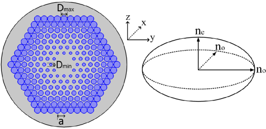
For this study, we modeled microstructured WGs with a hexagonal structure. The depressed cladding was formed by up to seven rings of cylindrical tracks whose centers were arranged hexagonally, as shown in Fig. 1. These tracks can be written in the bulk of a -cut LiNbO3 crystal by direct fs laser irradiation using a transverse inscription geometry. We found experimentally (the results will be published elsewhere) that the track diameter (in []) and the induced RI contrast depend on the laser pulse energy (in [nJ]) as follows:
| (1) |
where nJ is the energy threshold of the micro-objective used for inscription (numerical aperture ). These relations were found to be valid for a laser repetition rate of 11 MHz and the optimum (sample translation) inscription speed of 10 or 20 mm/s (determined by a trade-off between inscription depth and laser pulse energy), up to a maximum available laser pulse energy of approximately nJ. It follows that can be at most or . Note that at laser pulse energies approaching the maximum value the smoothness of the inscribed tracks may be compromised due to a strong self-action of the circular laser beam [23]. In our inscription experiments in LiNbO3 (which will be described in detail in a future work), RI contrast reconstruction was performed by quantitative phase microscopy (QPM) at the optical microscope. The QPM reconstruction method relies on processing “-stack” images of each individual track by using both commercial and in-house software. This procedure was calibrated by measuring standard optical fibers with known specifications. Further, the experimentally observed intensity distributions of various WG modes were found to be in good quantitative agreement with the results of numerical modeling.
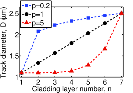
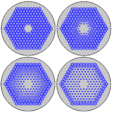
As mentioned in the introduction, a natural strategy to extend the spectral range of low-loss operation of the WG structure, is to allow the track diameter to differ from one ring to another with the exterior rings that have large tracks. The rate of growth of the track size from the innermost to the outermost ring can be parameterized with a single parameter , so that the track diameter in the -th ring is:
| (2) |
where and are the respective maximum and minimum diameters. Examples of how the growth rate parameter changes the track diameter in a seven-ring WG structure and the cross-sections of structures for different values of are given in Fig. 2.
Maxwell’s equations were solved to find out the complex effective RIs of the modes of the structure for the O and E polarisation states. The confinement losses (in decibels per centimeter) were computed from the imaginary part of effective RI through the formula , where is given in micrometers. Details of the numerical computation can be found in [13].
3 Eigenmodes of anisotropic microstructured WGs by PWM
Maxwell’s equations for monochromatic optical waves of angular frequency propagating along the axis of the coordinate system in a transparent, uniaxial crystal with the optical axis and of permittivity yield the following wave equation for the magnetic field vector :
| (3) |
where is the free-space wave number, and
Here, are the O and E RIs of the (intact domain of) crystal, and the distance- and time-dependence of the electromagnetic field: is assumed, where is the propagation constant of the mode propagating in the structure. For a crystal hosting a depressed-cladding WG with the track RI contrast , we can use the approximation introduced in [24] and express the RIs as:
To apply PW decomposition, the WG structure should be put in a box and tiled periodically along the - and -axes. The box should not be too large in order not to include a large area of unmodified material around the structure and, at the same time, should not be too small in order to avoid overlapping of modes in adjacent computational cells. Thus, the size of the box has to be a parameter for the calculations.
The second equation in Eq. (3) can be used to exclude from the first equation and, thus, obtain:
| (4) |
Equations (4) can be solved using the PWM [20, 21] to find out the (real) eigenvalues and eigenvectors . For this purpose, we used the following expansions in terms of PWs:
| (5) |
with unknown complex amplitudes , and , . Substituting these expansions into Eq. (4) and equalising the coefficients of the same exponential factors one can obtain the following linear equations for the modal amplitudes , :
| (6) |
where
From Eq. (6), one can determine and . The transverse components of the electric field and the longitudinal component of the Poynting vector will be then given by
| (7) |
The solution of Eq. (6) involves the calculation of Fourier harmonics of the mode profiles. For arbitrary shapes of the tracks of the WG structure, numerical methods have to be employed to calculate the Fourier coefficients, including, when necessary, digital image processing of real structure cross-sections [25]. In the special case of cylindrical tracks (circular cross-sections), however, analytical expressions for the Fourier coefficients can be found. Let denote any of , , with if and if . For cylindrical tracks of radii , one can obtain:
| (8) |
Here is the area of the surrounding box, is the Bessel function of the first kind, and are the coordinates of the center of the th track.
3.1 Numerical results by PWM and comparison with FEM
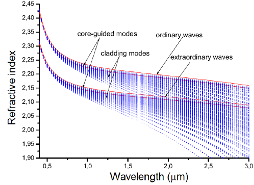
For practical applications, microstructured WG structures built of low-RI-contrast tracks should feature low confinement losses and, thus, need to have a fairly large number of cladding layers [13]. For these calculations, we considered seven-ring structures with the pitch , the track radius and the track RI contrast . The Fourier coefficients and matrices , , etc. were calculated for values of the indices up to , and 578 PWs were used. These PWs included mostly modes propagating along the -axis. The eigenvalue problem was solved numerically using the “cg.f” program from the “EISPACK” package (NetLib). Figure 3 shows the computed modes of the structure. We can note an overlap between the O and E polarisations at the wavelength . This overlap will lead to additional losses in the E mode due to a perturbation induced in the WG.
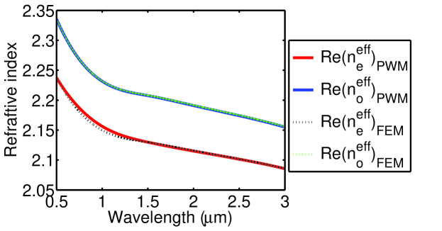
In Fig. 4, the effective RI profiles for the fundamental mode are compared to those obtained using the FEM. The PWM and FEM results are in excellent agreement for the O polarisation, whereas a small deviation within the wavelength range to can be observed for the E polarisation. This is likely due to a leakage of the E mode with lower RI into the higher-RI O polarisation [13], which is not accounted for by PWM calculations. The effective mode index values at different wavelengths as obtained from PWM and FEM calculations are given in Table 1.
| () | ||||||
|---|---|---|---|---|---|---|
| 0.5 | 2.33624 | 2.23809 | 2.3354 | 2.2372 | 2.33543 | 2.23728 |
| 1 | 2.23297 | 2.15087 | 2.23 | 2.1498 | 2.23001 | 2.14791 |
| 1.5 | 2.20986 | 2.13135 | 2.2039 | 2.129 | 2.20547 | 2.12545 |
| 2 | 2.19398 | 2.11805 | 2.1847 | 2.1087 | 2.18470 | 2.10877 |
| 2.5 | 2.17775 | 2.1045 | 2.165 | 2.098 | 2.16498 | 2.09173 |
| 3 | 2.15921 | 2.08905 | 2.1431 | 2.0758 | 2.14301 | 2.07285 |
4 Optimisation of WG structural parameters by FEM simulations
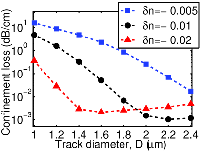
To minimise the confinement losses in the WG structure at the long wavelengths and, thus, extend the spectral range where the loss figures for the modes are acceptably low, we performed FEM simulations. This is because the PWM in its current formulation does not allow to calculate the imaginary parts of the effective mode indices. To find the leakage losses with the PWM, one should compute the localization coefficients for the modes or, alternatively, include an absorbing medium at the boundary of the computational supercell. The first approach would require the “calibration” of the losses for given localization coefficients, while the second approach is similar to using a PML absorber as in the FEM. We assume here 1 dB/cm to be an acceptable loss level for technological applications. A simple idea for addressing the numerical optimisation problem described in this section came from the observation that the confinement losses become monotonic functions of wavelength at sufficiently long wavelengths. Thus, one can vary different WG structural parameters at a fixed wavelength of interest, and only when the best loss figures are obtained, perform the full wavelength scan. This makes the optimisation procedure much less time consuming and, thus, practically feasible. The FEM results presented here refer to the fundamental mode of the structure, which was selected using the criterium of ’minimum effective mode area’ during the wavelength scanning [13]. The RI contrast induced by fs inscription is the most important parameter for mid-IR operation (and successful optimisation) of the WG. Figure 5 illustrates the dependence of the confinement loss on the track diameter at the wavelength for a seven-ring, uniform () structure with different values of . It is seen that for and there is a “plateau” of low losses over the diameter range 2.2 to 2.5 and 1.4 to approximately 2.2, respectively. Remarkably, such a plateau does not appear for lower RI contrasts, which are typically obtained by low-repetition rate fs laser inscription [23]. As we mentioned in Sec. 2, the RI contrasts of smooth tracks that can be achieved in crystals with current fs micro-fabrication technology are around or . Higher RI contrasts can still be obtained by fs inscription, with the fs laser creating severe damage tracks inside the bulk at the focal volume [26, 27]. Damage tracks, however, are not smooth and, thus, typically not suitable for low-loss light guiding.
The influence of a varying track diameter among the different cladding layers on the loss properties of the WG at the wavelengths and is illustrated by Fig. 6. Our simulations showed that the most interesting range of growth rate parameter values is . We can see from Fig. 6 that as decreases from 1, the confinement loss also decreases up to much lower values than that of a uniform structure (corresponding to when ). At , the loss profile is flat over the range (yielding and , ) to for the maximum track diameter . For a uniform structure yields lower confinement loss than . On the other hand, the loss for a structure with is higher than that for the uniform structure at . Differently, at the decrease of the confinement loss with decreasing values is approximately linear for both and . The smallest loss value dB/cm is obtained for very close to 0 and . The possibility of achieving such low loss figures at makes the WG suitable for mid-IR applications. Note that the transparency region of the WG can be further extended to longer wavelengths by increasing and properly fitting the parameter to the RI contrasts being used.
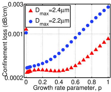
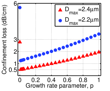
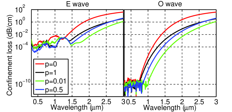
Figure 7 shows the variation of the confinement loss across the wavelength range 0.3 to 3 for WG structures with various growth rate parameters. One can see that while for a uniform structure the losses in both O and E polarisations are below 1 dB/cm for wavelengths up to approximately , the spectral range where the losses are acceptably low is extended up to for a structure with . The optimisation of the growth rate parameter results in a reduction of the losses in both polarisations by two orders of magnitude at . One may also notice that while the confinement losses of a WG with are lower than those of a WG with for wavelengths below , a reversal of trend happens at the wavelengths above . Further, Fig. 6 highlights the distinctly different behaviours of the confinement losses in the O and E polarisations at the low wavelengths. The confinement loss for the E wave stops decreasing with decreasing wavelength below some wavelength which is specific to the WG structure, and features resonance effects. The critical wavelengths below which such behaviour is observed are , , and for WGs with the respective growth rates , , and . This resonance behaviour which is peculiar to E-polarised propagating waves in anisotropic WGs, stems from the coupling of the E-polarized fundamental mode to the radial modes of O polarisation and consequent leakage of the E wave through these modes [19].
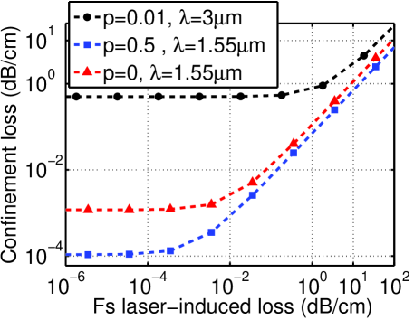
The results presented so far were obtained by assuming that the RI change induced in the material by direct fs laser inscription is a real value. In fact, as mentioned in the introduction, the fs irradiation always induces material absorption, which needs to be accounted for in the WG design. To this end, we computed the confinement loss in a WG with and at , and with at for a range of fs laser-induced loss values. The results are shown in Fig. 8, which reveals that the higher is the confinement loss of the WG, the lower is the WG sensitivity to the imaginary part of the induced RI contrast. Indeed, induced losses of up to 1 dB/cm do not affect the confinement loss at , whereas the effect of induced loss is more important at , where the WG exhibits lower confinement loss. We note that the imaginary part of the modified RI could be measured by using, for example, the Born scattering interferometry method recently proposed in [16].
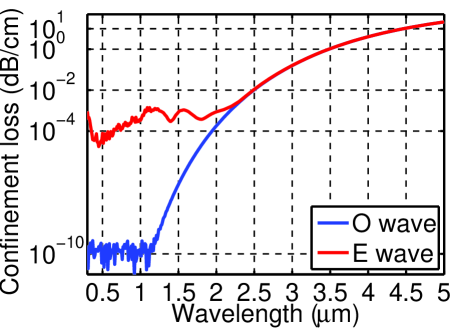
Finally, we included in our design procedure also the relationship between induced RI contrast and track size . Indeed, as we mentioned before, the dependence of and on the laser pulse energy makes such parameters correlated if the sample translation speed is fixed (Eq. (1)). Note that it is possible to experimentally trim these parameters to the desired values by tuning both the laser pulse energy and the sample translation speed, as both produce albeit connected but not identical changes to and . Simulation results are presented in Fig. 9, which shows the variation of the confinement losses in the O and E polarisations as a function of wavelength for a seven-ring WG structure with a growth rate parameter of and where the RI contrast was changed from one ring of tracks to another following the change in the track size. It is seen that the spectral region where the losses in both polarisations are below 1 dB/cm extends up to for this optimised structure.
5 Conclusions
We have presented a numerical approach to the optimisation of the guiding properties of depressed-index cladding WGs that can be fabricated in a -cut LiNbO3 crystal by direct fs laser inscription. The approach accounted for both a suitable variation of the track size among different cladding layers, the relationship between track size and induced RI contrast, and the losses induced on the tracks by fs irradiation. We have shown that the spectral region where the confinement losses in both O and E polarisations are acceptably low (below 1 dB/cm) can extend up to a wavelength of for optimised, hexagonal WG structures with seven rings of tracks. This makes such structures suitable for mid-IR applications. We note that the possibility of further extending the low-loss operation region of these WGs depends on the ability to experimentally achieve higher RI contrasts than those that are feasible by use of current fs micro-fabrication technology, as well as to increase the track sizes.
Acknowledgments
The authors would like to acknowledge support by the Leverhulme Trust (grant RPG-278) and the Engineering and Physical Sciences Research Council (grant EP/J010413/1).