Thermoelectric effects in FeCoMgOFeCo magnetic tunnel junctions
Abstract
We studied the thermoelectric coefficients (Seebeck and thermal conductance) of FeCoMgOFeCo(001) magnetic tunnel junctions (MTJs) from first principles using a generalized Landauer-Büttiker formalism. FeCoMgOFeCo(001) MTJs usually yield smaller thermoelectric effects compared with epitaxial FeMgOFe(001) MTJs. The (magneto-) Seebeck effect is sensitive to the details of the FeCoMgO interfaces. Interfacial oxygen vacancies (OVs) can enhance the thermoelectric effects in MTJs greatly. We also compute angular dependent Seebeck coefficients that provide more information about the transport physics. We report large deviations from the Wiedemann-Franz law at room temperature.
pacs:
72.25.-b, 73.50.lw, 72.10.BgI Introduction
Spin caloritronics is a research direction STB2012 ; Gerrit2012 that provides alternative strategies for thermoelectric waste heat recovery and cooling. Seebeck KU2008 and Peltier JF2012 effects in magnetic nanostructures become spin-dependent, i.e., different spin channels contribute differently and can be modulated by the magnetization direction. Moreover, in magnetic heterostructures a thermal spin transfer torque (TST) hatami2007 ; jxtL2011 can be induced by heat currents.
Magneto thermoelectric effects in magnetic tunnel junctions (MTJs) were measured recently walter2011 ; AB2013 ; lie2011 ; Hu2012 partly motivated by its potential applications in magnetic random access memory devices. The Seebeck rectification effect in MTJs might be beneficial for scavenging waste heat. Hu2012 The reported Seebeck coefficients () in MgO based MTJs vary from 22 V/K (Ref. Hu2012, ) to -770 V/K (Ref. AB2013, ) for similar barrier thicknesses while the difference in Seebeck coefficients between magnetic parallel and antiparallel configurations, = were measured from -8.7V/K (Ref. walter2011, ) to -272V/K (Ref. lie2011, ). Seebeck coefficients as high as mV/K, have also been reported. Lin2012 ; JM2013
Due to the difficulty in determining the temperature difference across the tunneling barrier, the intrinsic Seebeck coefficient cannot be measured directly but has to be determined via thermal modelling, which introduces uncertainties. The calculations based on realistic electronic band structures yield Seebeck coefficients less than 60V/K at room temperature (RT). MC2012 ; CH2013
For MTJs, the energy dependence of the conductance is sensitive to the band alignment between insulator and metal. Small changes in the computational procedures and parameters can result in quite different thermoelectric coefficients. In this paper, we address the complications in order to increase the accuracy of the predictions and find out how large the Seebeck coefficients might become as well as its tunability by interface engineering.
The Landauer-Büttiker formalism has been generalized to thermal transport and to thermoelectric cross-effects by Butcher, butcher1990 which treats electrical transport in terms of transmission through a scattering region between electron reservoirs. Knowing the energy dependent conductance, the Seebeck coefficient and electric thermal conductance can be calculated.
In this paper, we combine the Landauer-Büttiker formalism for spin polarized thermal and electrical transport with realistic electronic band structures to compute the Seebeck coefficient and thermal conductance in FeCo-MgO MTJs. In Sec. II we present the details of the formalism. In Sec. III the method is used to calculate the thermoelectric coefficients of FeCoMgOFeCo with perfect interfaces and in the presence of oxygen vacancies (OVs). In Sec. IV we summarize our results.
II Thermoelectric Coefficients
We model a device sandwiched by left (L) and right (R) electron leads with chemical potential difference and temperature bias . The heat flow and electric current I then readGroot
| (1) |
where is the electrical resistance and the Seebeck coefficient and Peltier cooling coefficient are related by the Onsager-Kelvin relation .
The spin-dependent conductance
| (2) |
where denotes spin, is the energy-dependent spin transmission probability, the Fermi occupation is a function of energy , electrochemical potential , and temperature , and we here define .
In the linear response approximation, total electric current reads
| (3) | |||||
The Seebeck coefficient is obtained by setting in Eq. (3) as
| (4) | |||||
where
| (5) |
and C. When the energy dependent conductance varies slowly around fermi level, one can use the Sommerfield expansion and Eq. (4) becomes
| (6) |
with Lorenz number V2K-2.
There are two parallel channels of heat transport, viz. the electrons and the phonons. We calculate only the electron part in the presence of a nonequilibrium thermal distribution. The electronic contribution to the thermal conductance is defined as
| (7) |
where is given in the Landauer-Büttiker formalism by Ref. butcher1990, as
| (8) |
At low temperatures, the leading term in the Sommerfield expansion is
| (9) |
We may disregard the term when , which leads to the Wiedemann-Franz (WF) relation
| (10) |
The tunnel magneto resistance ratio (TMR) is defined in terms of the conductances for parallel (P) and anti-parallel (AP) configurations:
| (11) |
where .
Similarly tunnel magneto-Seebeck (TMS) and tunnel magneto heat resistance ratios (TMHR) as
| (12) |
and
| (13) |
At sufficiently low temperature, the WF relation may be used in Eq. (13) and the value of TMR.
III THERMOELECTRICS OF FeCoMgOFeCo(001)
III.1 Model
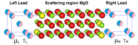
We consider a two-probe device consisting of a MgO
barrier and two semi-infinite ferromagnetic leads as shown in Fig.
1. The electric current is applied along the (001) growth
direction, The atoms at interfaces are kept unrelaxed in their
bulk bcc positions. Oxygen vacancies (OVs) in MgO are
energetically favorable because they relax the compressive strain
at the interface during crystal growth.PG We assume that
OVs only exists at the first atomic layer at the interface between
the MgO barrier and FeCo.
The thermoelectric coefficients are governed by the energy dependence of the conductance. While the lateral supercell method can be used to handle the impurity scattering in metallic system, Ke06 the required high accuracy of the energy-dependent conductance would be difficult to obtain for the present system, since in MTJs, the error bar due to the disorder configurations usually is much larger than that in metallic systems because of the absence of self-averaging over the Brillouin Zone (BZ).
The density functional theory calculation with coherent potential approximation (CPA) is therefore more suitable for a quantitative theoretic analysis of spin transport through FexCoMgOFeyCo1-y MTJs, where are numbers between 0 and 1. The transport properties are evaluated here by the Keldysh nonequilibrium Green function including nonequilibrium vertex corrections.ke08 The method is generalized to handle non-collinear magnetization similar to non-collinear problem in scattering wave function method.wang2008
We use 4104 k points in the full two-dimensional BZ to ensure excellent numerical convergence. Other details of the electronic structure and transport calculation can be found in Ref. ke08, . Our CPA method can only handle disorder in the scattering region; we use virtual crystal approximation (VCA) to deal with the potential functions in the alloy leads. To prove VCA is a qualified method, we study the FeFeCoMgOFeCoFe MTJs with alloy FeCo in the scattering region, which 6 monolayers(6ML) of FeCo is enough to add coherent potential as leads, then we compare the energy-dependent conductance between FeCoMgO(6ML)FeCo (VCA) with FeFeCo(6ML)MgO(6ML)FeCo(6ML)Fe. Our calculations shows that results are not sensitive to this simplification of the electronic structure of the leads.
| concentration | disorder | TMR(%) | |
| 3 | Fe0.25Co0.75 | clean | 577 |
| Fe0.50Co0.50 | clean | 934 | |
| Fe0.75Co0.25 | clean | 1003 | |
| Fe0.50Co0.50 | 5%OVs | 209 | |
| 5 | Fe0.25Co0.75 | clean | 853 |
| Fe0.50Co0.50 | clean | 900 | |
| Fe0.75Co0.25 | clean | 1017 | |
| Fe0.50Co0.50 | 5%OVs | 113 | |
| 7 | Fe0.25Co0.75 | clean | 902 |
| Fe0.50Co0.50 | clean | 957 | |
| Fe0.75Co0.25 | clean | 1061 | |
| Fe0.80Co0.20 | clean | 1178 | |
| Fe0.50Co0.50 | 5%OVs | 90 | |
| Exp. lie2011 | Co0.6Fe0.2B0.2 | 70140(RT) | |
| Exp. SI2008 | Co0.2Fe0.6B0.2 | 604(RT), 1144(5K) | |
| 9 | Fe0.25Co0.75 | clean | 947 |
| Fe0.50Co0.50 | clean | 1033 | |
| Fe0.75Co0.25 | clean | 1101 | |
| Fe0.50Co0.50 | 5%OVs | 82 | |
| Exp. walter2011 | Fe0.50Co0.50 | 330(RT) |
The TMR ratios calculated for different barriers in our calculation are compared with experiments in Table 1. 3ML is the thinnest MgO barrier achievable by current experiment technique.JC2013 In experiments,SI2008 TMR ratios can be maximized through controlled annealing and other grow conditions reaching our theoretical values for the clean interfaces. However, most likely the samples used in the thermoelectric experimentswalter2011 ; lie2011 with lower TMR ratios contains 3%OVs5%OVs.
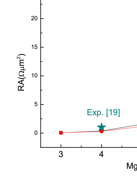
In Fig. 2, we compare RA with published experiments. For a 7ML thick MgO barriers (1.6nm) with PC, our calculation yields 23.8m2(clean) and 12m2(5%OVs), close to the measured junction resistance of 17 m2 for 1.5nm thick tunnel junctions.lie2011
III.2 Energy dependent conductance
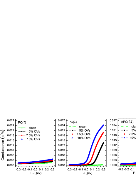
Even though both FeMgOFe and FeCoMgOFeCo MTJs show large TMR ratios, their spectral conductance is quite different. Resonant transmission channels exist just below the Fermi level in Fe-MgO based MTJs,jxtL2011 but not in FeCo-MgO based MTJs. Fig. 3 shows the energy dependence of the conductance of Fe0.5CoMgO(5ML)Fe0.5Co0.5 (001) MTJs with given concentration of OVs at both interfaces for both PC and APC. The energy window in the plots corresponds to 11kBT at room temperature (300K), where kB is the Boltzmann constant. The slope of the energy-dependent transmission around the Fermi energy dramatically changes by only small amounts of OVs. The APC shows a similar tendency as PC shown in the Fig. 3.
In order to understand this, we show results for a wider energy window of 1.2eV in Fig. 4. Two peaks exist above the Fermi level for minority-spin in Fe0.5CoMgO(5ml)Fe0.5Co0.5(001) MTJs. The OVs broaden the peaks and shift their towards the Fermi level up to a certain amount also enhance the conductance around the Fermi level.
Since thermoelectric effects are closely related to the slope of energy-dependent conductance near the Fermi level, a proper amount of OVs at FeCoMgO interfaces enhance the Seebeck and Peltier constants.
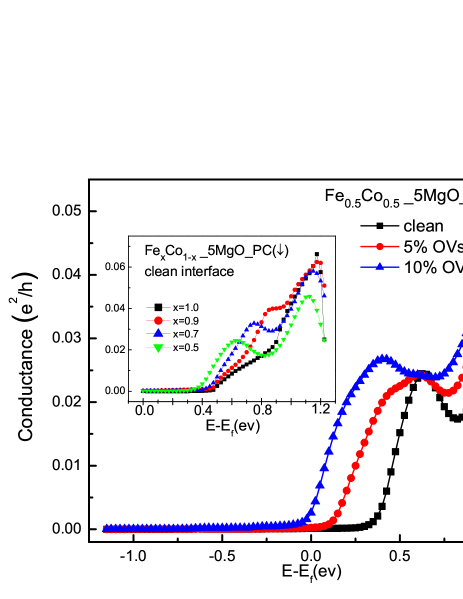
The origin of these two peaks for MTJs with random alloys is not obvious. Fortunately, similar conductance peaks also exist in epitaxial FeMgOFe MTJs. The inset of Fig. 4 shows the energy-dependent conductance of MTJs with different alloy concentrations (including pure Fe) as electrodes. For epitaxial FeMgOFe (black square), there is one clear peak exist at 1eV above the Fermi energy and a shoulder around 0.8eV. with 10% Co atoms doping (red circles), the shoulder develops into a plateau. At higher Co concentrations (x=0.7, 0.5), the plateau becomes a second peak near the Fermi level.
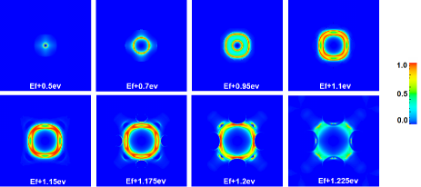
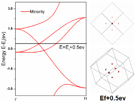
For epitaxial FeMgOFe MTJs, we can identify the origin of these conductance peaks by inspecting the band structure of Fe. We plot the k∥ resolved transmission for the minority-spin bands in FeMgO(5ML)Fe MTJs at different energies in Fig. 5. From 0.5eV to 1.2eV, we observe a ”hot” ring with energy-dependent diameter. The maximum transmission can reach unity, which is evidence for resonant tunneling channels that emerge form six small symmetry ”bubbles” in constant energy surface at 0.5eV as shown in Fig. 6. These bubbles have sharp edges that result in two resonant hot concentric rings. As these ”bubbles” get larger with energy, the diameter of the hot rings increases. At even higher energies, these ”bubbles” hybridize with other transmission channels and loose their resonant character.
III.3 Seebeck coefficient
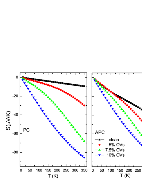
Seebeck coefficients can be obtained by Eq. (4), the energy range of integration depending on the temperature. We choose 0.3eV in this paper, which corresponds to a precision of more than 99.5% for T=300K. Fig. 7 exhibits the Seebeck coefficient in Fe0.5CoMgO(5ML)Fe0.5Co0.5 MTJs with different concentration of OVs at the FeCoMgO interface. The clean interface (black squares) in MTJs gives the smallest Seebeck coefficient, while an increasing OVs enhances the effect until 10%OVs (blue down-triangles) by an order of magnitude for PC. The magneto-Seebeck is 369.3% and -3.6% for clean and 10%OVs at both interfaces, respectively. Moreover, we give Seebeck coefficients and the corresponding magneto-Seebeck ratio for different MgO barriers in Tab. 2.
Firstly, the Seebeck coefficient gets larger with thicker MgO barriers with identical interface disorder for both PC and APC. For example, the Seebeck coefficient of MTJs with 9 monolayers MgO is 210 times larger than that of with 3 monolayers for different interfacial quality and configurations, whereas the conductance changes by 5 orders of magnitude. Seebeck coefficients are clearly not sensitive to MgO barrier thickness.
Secondly, the sign of the Seebeck coefficient does not change with thickness at RT, and the value of Seebeck coefficient is enhanced by the OVs at the interface for a certain layers of MgO. In our study, the thermoelectrical effect are maximized for 10%OVs for 5 monolayers MgO barrier, which can be understood from Fig. 4.
Thirdly, the order and sign of the magneto-Seebeck ratio () is sensitive to the details of the interfacial roughness. Take the calculated results for 5 monolayers MgO in Tab. II and Fig. 3 as an example. When the interface is clean, the APC has larger Seebeck coefficient than the PC, while the magneto-Seebeck is large and positive. When the interface contains some OVs, both PC and APC display a larger thermoelectric effect. But always grows faster than , which can be seen by inspecting the slopes around the Fermi level in Fig. 3. So changes sign in some cases lead to a very small . For samples with a small at RT, we expect the sign will change at low temperature.
The existence of OVs at the interfaces has a great effect on the slope of the energy-dependent conductance at the Fermi level, which means we can tune thermoelectric effects by the concentration of OVs at the interfaces. Our calculation of Seebeck coefficients and TMS of 9ML MgO barriers give an estimation with 7%OVs at the interfaces are consistent with the experiment results walter2011 in Tab. 2 for PC and APC, respectively.
| disorder | P | AP | (%) | |
| 3 | clean | -2.09 | -23.82 | 1039.7 |
| 5%OVs | -6.93 | -19.41 | 180.1 | |
| 7.5%OVs | -12.87 | -16.65 | 29.4 | |
| 10%OVs | -14.78 | -25.77 | 74.4 | |
| 5 | clean | -8.08 | -37.92 | 369.3 |
| 5%OVs | -22.48 | -52.79 | 134.8 | |
| 7.5%OVs | -55.80 | -69.23 | 24.1 | |
| 10%OVs | -77.36 | -74.70 | -3.6 | |
| 7 | clean | -15.13 | -50.26 | 267.6 |
| 5%OVs | -40.46 | -76.44 | 88.9 | |
| 7.5%OVs | -101.33 | -99.20 | -2.2 | |
| 10%OVs | -124.93 | -98.93 | -26.3 | |
| 9 | clean | -23.12 | -61.50 | 166.0 |
| 5%OVs | -62.79 | -99.80 | 58.9 | |
| 6.5%OVs | -112.86 | -119.05 | 8.4 | |
| 7%OVs | -132.10 | -124.15 | -6.4 | |
| 7.5%OVs | -149.17 | -127.99 | -16.5 | |
| 10%OVs | -155.79 | -121.74 | -30.0 | |
| Exp. walter2011 | -107.9 | -99.2 | -8.8 |
Although MTJs with 9 monolayers MgO have the largest Seebeck coefficient as shown in Table 2. However, since its conductance and thermoelectric current is so small, which would result in lower thermoelectric current, and 3MgO junctions still generate the largest thermoelectric power for a given temperature difference.
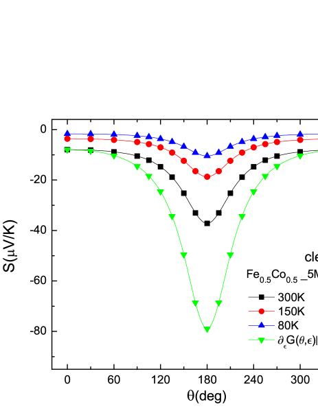
The angular dependent Seebeck coefficient (ADSC) and conductance can provide more information about the transport process. We compute the ADSC at 300K (black squares), 150K (red circles), 80K (blue up-triangles) for Fe0.5CoMgO(5ML)Fe0.5Co0.5 in Fig. 8. The horizontal axis denotes the relative angle of magnetization between the two leads. The Seebeck coefficient varies slowly from PC to 90∘, and drastic from 90∘ to APC. The ADSC looks is consistent with the report.AGS2013
This unusual variation deviates strongly from the familiar trigonometric
dependence for thick layers. The phenomenon can be simply explained as
follows, the angle dependent conductance could be read as , and Eq. (6) as . If
is constant
for different angle, behave as 1/cos. If,
on the other hand cos, the Seebeck coefficient becomes
constant as . We compare a Seebeck coefficients at 300K (black
squares) with 1/ (green down-triangles) in Fig. 8.
The similar behavior can be interpreted as evidence for AGSC.
III.4 Thermal conductance
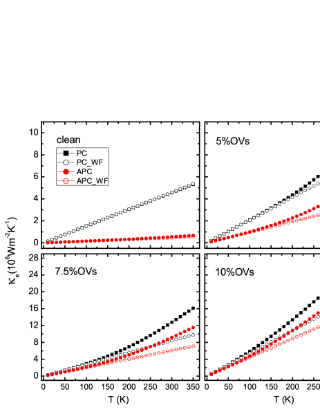
The electronic heat conductance depends on the symmetric component of the spectral around the Fermi level. Fig. 9 shows the thermal conductance of Fe0.5CoMgO(5ML)Fe0.5Co0.5(001) with 0% 5%, 7.5%, 10%OVs at both interfaces, respectively. The thermal conductance is increased by the OVs similar to the charge conductance and Seebeck coefficient. 10% OVs enlarge the thermal conductance by 5 and 33 times for P and AP configurations compared to clean interfaces at RT, respectively. The tunnel magneto heat resistance ratios (TMHR) is 744.4% and 23.3% for clean and 10%OVs at both interfaces, respectively. The order of TMHR changes greatly by the OVs at the interface.
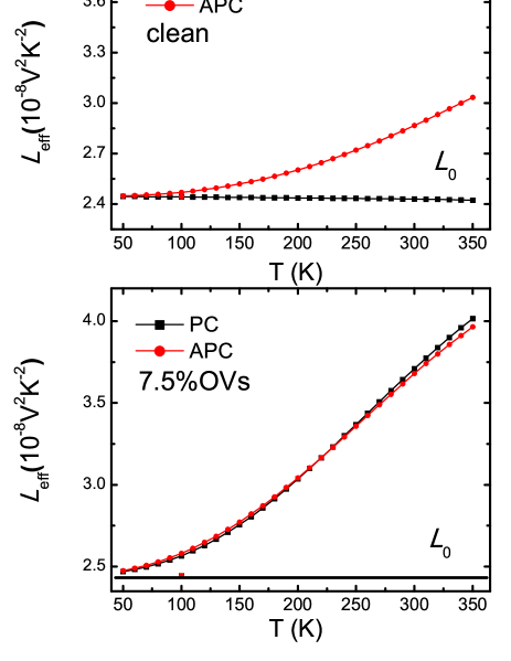
Additional, we tested the WF law as a function of temperature. At low temperature, and the WF law holds. When the thermal conductance does not vary linear with temperature due to a breakdown of the Sommerfield approximation or the Seebeck coefficient is getting large (see Fig. 7), the WF relation is no longer valid, and deviation are observed in in Fig. 9. We define an effective Lorenz number from
| (14) |
to parameterize the study the breakdown of the WF Law by compare it with the Lorenz constant V2K-2. We display the temperature dependent effective Lorenz number for different OVs concentrations in Fig. 10, in which is found to become significantly enhanced from L0 with increasing temperature. We show the thermal conductance and corresponding TMHR of MTJs for different MgO barriers in Tab. III, Firstly, the thermal conductances decrease sharply with thicker MgO barriers and interfacial roughness for both PC and APC. Secondly, the thermal conductance is enhanced by the interfacial OVs with a fixed thickness, whereas, the order of tunnel magneto heat resistance ratios is decreased. Thirdly, the order of TMHR does not change to much with the same interfacial roughness for thicker MgO barriers.
| disorder | P | AP | ||
|---|---|---|---|---|
| 3 | clean | 128.67 | 16.44 | 682.7 |
| 5%OVs | 147.26 | 55.28 | 166.4 | |
| 7.5%OVs | 169.91 | 84.09 | 102.1 | |
| 10%OVs | 198.13 | 122.99 | 61.1 | |
| 5 | clean | 4.56 | 0.54 | 744.4 |
| 5%OVs | 7.35 | 4.15 | 77.1 | |
| 7.5%OVs | 12.77 | 9.17 | 39.3 | |
| 10%OVs | 22.03 | 17.86 | 23.3 | |
| 7 | clean | 0.31 | 0.037 | 737.8 |
| 5%OVs | 0.84 | 0.53 | 58.5 | |
| 7.5%OVs | 2.27 | 1.59 | 42.8 | |
| 10%OVs | 5.73 | 4.15 | 38.1 | |
| 9 | clean | 0.027 | 0.003 | 800.0 |
| 5%OVs | 0.137 | 0.087 | 57.5 | |
| 7.5%OVs | 0.581 | 0.383 | 51.7 | |
| 10%OVs | 2.364 | 1.552 | 52.3 |
IV Summary
In conclusion, we computed the thermoelectric coefficients of FeCoMgOFeCo MTJs from first-principles. OVs at FeCoMgO interfaces can be used to engineer thermoelectric effects. While interface disorder can greatly increase the Seebeck coefficient, it suppresses the magneto-Seebeck ratio. The vacancy concentration is therefore an important design parameter in switchable thermoelectric devices based on magnetic tunnel junctions.
ACKNOWLEDGMENTS
We gratefully acknowledges financial support from National Basic Research Program of China (2011CB921803, 2012CB921304), NSF-China (11174037, 61376105), JSPS Grants-in-Aid for Scientific Research (25247056, 25220910), the EU-RTN Spinicur, and DFG Priority Programme 1538 ”Spin-Caloric Transport” (GO 944/4).
References
- (1) S. T. B. Goennenwein and G. E. W. Bauer, Nature Nanotechnology 7, 145 (2012).
- (2) G. E. W. Bauer, Eiji Saitoh and Bart J. van Wees, Nature Materials 11, 391 (2012).
- (3) K. Uchida, S. Takahashi, K. Harii, J. Ieda, W.Koshibae, K. Ando, S. Maekawa, and E. Saitoh, Nature 455, 778 (2008).
- (4) J. Flipse, F.L. Bakker, A. Slachter, F.K. Dejene and B.J. van Wees, Nature Nanotechnology 7, 166 (2012).
- (5) M. Hatami, G. E. W. Bauer, Q. F. Zhang, and P. J. Kelly, Phys. Rev. Lett. 99, 066603 (2007).
- (6) X. Jia, K. Xia and G. E. W. Bauer, Phys. Rev. Lett. 107, 176603 (2011).
- (7) M. Walter, J. Walowski, V. Zbarsky, M. Münzenberg, M. Schäfers, D. Ebke, G. Reiss, A. Thomas, P. Peretzki, M. Seibt, J. S. Moodera, M. Czerner, M. Bachmann and C. Heiliger, Nature Materials 10, 742 (2011).
- (8) A. Boehnke, M. Walter, N. Roschewsky, T. Eggebrecht, V. Drewello, K. Root, M. Münzenberg, A. Thomas and G. Reiss, Rev. Sci. Instrum. 84, 063905 (2013).
- (9) N. Liebing, S. Serrano-Guisan, K. Rott, G. Reiss, J. Langer, B. Ocker, and H. W. Schumacher, Phys. Rev. Lett. 107, 177201 (2011); J. Appl. Phys. 111, 07C520 (2012).
- (10) Z. H. Zhang, Y. S. Gui, L. Fu, X. L. Fan, J. W. Cao, D. S. Xue, P. P. Freitas, D. Houssameddine, S. Hemour, K. Wu, and C.-M. Hu, Phys. Rev. Lett. 109, 037206 (2012).
- (11) W. Lin, M. Hehn, L. Chaput, B. Negulescu, S. Andrieu, F. Montaigne, and S. Mangin, Nature Commun. 3, 744 (2012).
- (12) J. M. Teixeira, J. D. Costa, J. Ventura, M. P. Fernandez-Garcia, J. Azevedo, J. P. Araujo, J. B. Sousa, P. Wisniowski, S. Cardoso, and P. P. Freitas, Appl. Phys. Lett. 102, 212413 (2013).
- (13) M. Czerner and C. Heiliger, J. Appl. Phys. 111, 07C511 (2012).
- (14) C. Heiliger, C. Franz, and M. Czerner, Phys. Rev. B 87, 224412 (2013).
- (15) P. N. Butcher, J. Phys.: Condens. Matter 2, 4869 (1990).
- (16) de Groot S R and Mazur P 1984 Non-Equilibrium Thermodynamics (New York: Dover).
- (17) P. G. Mather, J.C. Read, and R.A. Buhrman, Phys. Rev. B 73, 205412 (2006).
- (18) S. Ikeda, J. Hayakawa, Y. Ashizawa, Y. M. Lee, K. Miura, H. Hasegawa, M. Tsunoda, F. Matsukura, and H. Ohno, Appl. Phys. Lett. 93, 082508 (2008).
- (19) S. Yuasa and DD Djayaprawira, J. Phys. D: Appl. Phys. 40, R337 (2007)
- (20) K. Xia, M. Zwierzycki, M. Talanana and P. J. Kelly, G. E. W. Bauer, Phys. Rev. B 73, 064420 (2006).
- (21) Y. Ke, K. Xia, and H. Guo, Phys. Rev. Lett. 100, 166805 (2008).
- (22) S. Wang, Y. Xu, and K. Xia, Phys. Rev. B 77, 184430 (2008).
- (23) J. C. Leutenantsmeyer, M. Walter, V. Zbarsky, M. Münzenberg, R. Gareev, K. Rott, A. Thomas, G. Reiss, P. Peretzki, H. Schuhmann, M. Seibt, M. Czerner, C. Heiliger, SPIN 03, 1350002 (2013).
- (24) P.X. Xu, V. M. Karpan, K. Xia, M. Zwierzycki, I. Marushchenko and P. J. Kelly, Phys. Rev. B 73, 180402(R) (2006).
- (25) C. Heliger, M. Czerner, N. Liebing, S. S. Guisan, K. Rott, G. Reiss and H. W. Schumacher, arXiv:1311.2750 (2013).