Signal Processor based on Gaussian Message Passing
A Signal Processor for Gaussian Message Passing
Abstract
In this paper, we present a novel signal processing unit built upon the theory of factor graphs, which is able to address a wide range of signal processing algorithms. More specifically, the demonstrated factor graph processor (FGP) is tailored to Gaussian message passing algorithms. We show how to use a highly configurable systolic array to solve the message update equations of nodes in a factor graph efficiently. A proper instruction set and compilation procedure is presented. In a recursive least squares channel estimation example we show that the FGP can compute a message update faster than a state-of-the-art DSP. The results demonstrate the usabilty of the FGP architecture as a flexible HW accelerator for signal-processing and communication systems.
I Introduction
Computationally demanding tasks such as channel estimation or equalization are omnipresent in modern communication and signal-processing systems. Algorithms for such tasks might be implemented on hardware accelerators, on a programmable processor such as a DSP or on an ASIP with a custom instruction set. Various attempts have been reported to bridge the gap between hardwired accelerators and programmable processors, where the trade-offs between performance and programmability have been subject of many studies[1]. The goal of this work is to design a signal processor or accelerator with an appropriate instruction set, which offers sufficient flexibility to perform a wide range of common signal-processing tasks. To achieve this, we leverage the theoretical framework of factor graphs (FGs) [2] and message-passing algorithms. More specifically, we focus on FGs that represent factorizations of (scaled) multivariate Gaussian probability distributions.
In [3] it is shown how widely-used algorithms such as recursive least squares (RLS), linear MMSE equalization, and Kalman filtering can be expressed with Gaussian message-passing (GMP) on a FG. GMP algorithms have applications in various different fields such as wireless communications [4], optical imaging [5], Time of Arrival (ToA) estimation [6], multiuser detection [7] or compressed sensing [8].
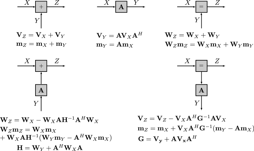
A FG is an undirected graph, where each node represents a function. In GMP messages, which are represented by a mean vector and a covariance matrix , or a transformed mean vector and a weight matrix are exchanged between nodes of a graph. The computational load is distributed among the nodes, which compute updates of the outgoing messages based on the incoming messages. The various types of nodes (i.e., functions) that are used in GMP are summarized in Fig. 1. The figure also displays the message update rules corresponding to each type of node.
To the best knowledge of the authors, there exists no programmable processing architecture with a datapath suited for solving GMP algorithms.
In this paper, we present a novel application specific instruction processor termed FGP which is able to perform the message updates for all basic types of nodes in GMP. Therefore, complex algorithms described by GMP can be readily executed on our processor. The computations in the FGP are based on a systolic array implementation of the Faddeev algorithm, which is able to efficiently compute all necessary matrix operations. Eventually, we demonstrate an appropriate compiler for the FGP and compare the throughput of the proposed implementation with a state-of-the-art DSP for a compound node message update.
II From GMP nodes to datapath architecture
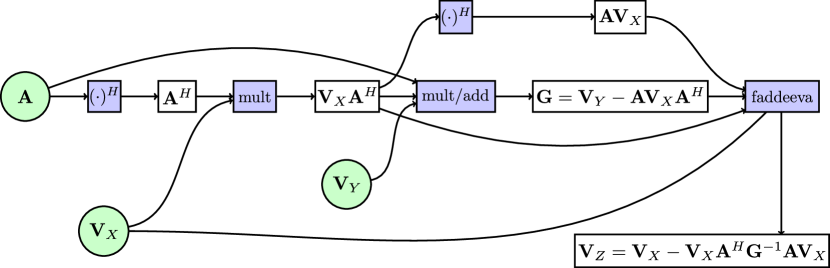
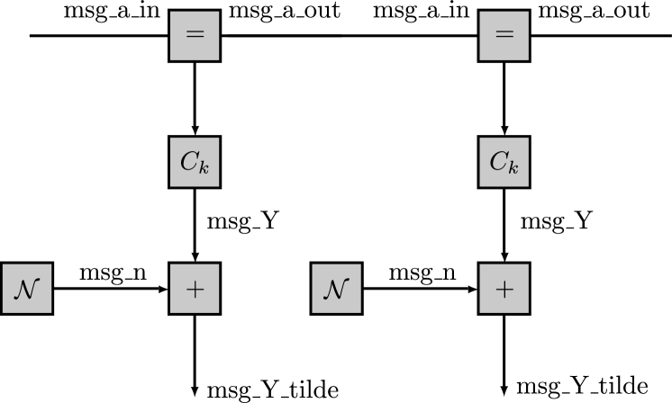
The FGP architecture is derived from the message update rules of the nodes in Fig. 1. Compound nodes are composed by two simple nodes. The expressions for the compound nodes consist of the same basic matrix operations as the ones for the simple nodes what facilitates the development of a datapath which is suitable for all nodes. The data dependency graph for the message update (covariance matrix only) computation of a compound node is shown in Fig. 2.
The outgoing message is computed with the incoming messages , and a state matrix defined the particular node. The purple boxes highlight the computations to be carried out, while the white boxes contain the intermediate results. The computations can be decomposed into three types111Hermitian transp. and negation are not considered as a separate operations.:
-
•
Matrix-matrix multiplication (e.g., )
-
•
Matrix-matrix multiplication with addition/subtraction (e.g., )
-
•
Schur complement (e.g., )
A suitable architecture for matrix computations of such a kind is the systolic array [9]. For the matrix-matrix multiplication (), a two-dimensional rectangular systolic array as shown in the blue box in Fig. 5 is sufficient. The processing elements (PEs) need to perform multiplications and additions. This so-called PEmult is shown in Fig. 3.
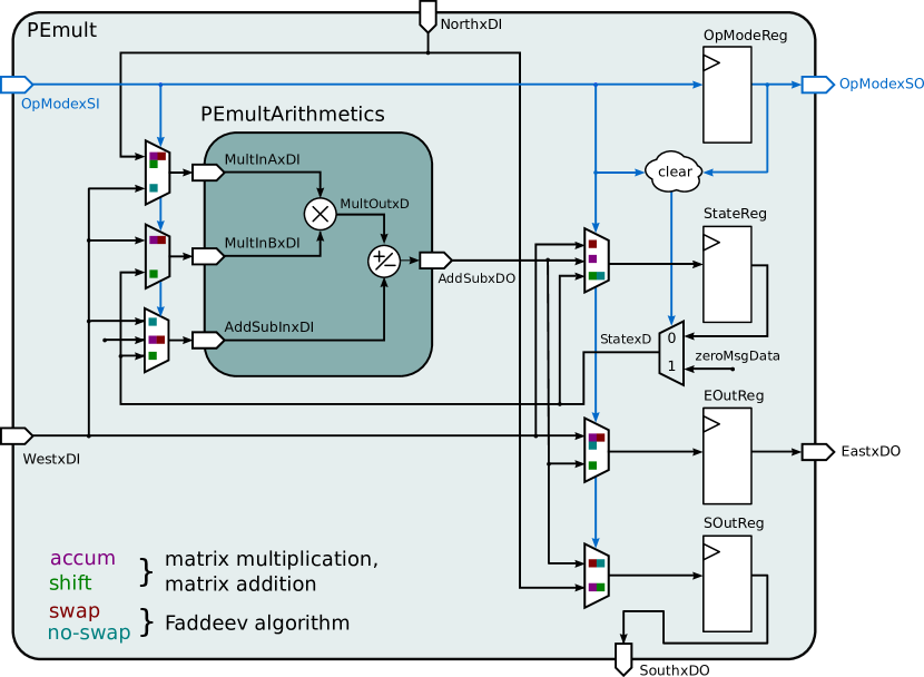
It supports different operation modes which will be explained next and contains both a real-valued multiplier and a real-valued adder/subtractor, which allows a complex-valued multiplication to be executed in four cycles. The adder is utilized in only two of the four cycles and in the remaining two cycles an additional number can be added to the final result. Hence, the second of the above mentioned computations () can be completed with the same rectangular array. Furthermore, the flow of data through the array and the rate at which input data must be provided is very regular. An additional advantage of this architecture becomes apparent when a matrix multiplication is followed by a matrix multiplication with subtraction as in the compound node example of Fig. 2. In this case, the result of the first matrix multiplication is stored in the StateReg of the PEmult. The subsequent operation can immediately be started since the matrix is already available and the matrices and can be shifted through the array from the “north” and the “west”, respectively.
The Schur complement for the third operation mode is computed with the Faddeev algorithm. The algorithm performs triangularization of the input matrix followed by Gaussian elimination. [9]. It is a favorable choice because it avoids direct matrix inversions. To this end, the rectangular systolic array requires a triangular extension as it is shown in the yellow box in Fig 5. A different kind of PEs capable of computing the absolute value and a complex division as shown in Fig. 4 is required in addition the PEmult. During Gaussian elimination, the PEmult performs the necessary swapping of the matrix rows for the pivoting.
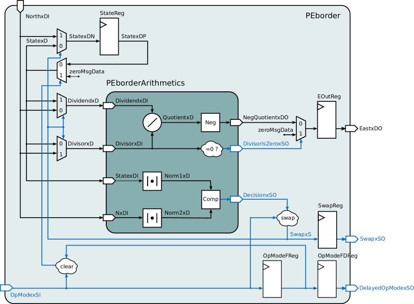
The complex-valued division is carried out using the relationship by employing one sequential divider222The divider performs a sequential radix-2 division in 4 cycles., two multipliers and one adder.
In order to avoid the deployment of three different systolic arrays we propose an architecture with a single systolic array whose processing elements support multiple modes of operation as explained in the following section.
III FGP Architecture
The FGP architecture is mainly determined by the operations of the GMP nodes. The systolic array with the presented PEs is the core part of the FGP as shown in Fig. 5.
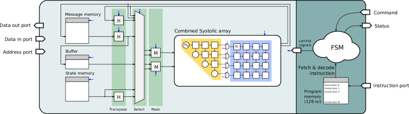
Further more, the processor contains a program memory (PM) and memories for the messages and the state matrix . Storing intermediate results during the execution of an operation is not required due to the systolic architecture where intermediate results are stored in the state of the systolic array (i.e., the result of the matrix multiplication in accum mode, which is used as input to the matrix multiplication in shift mode and as input to the Faddeev algorithm).
An instruction is fetched from the PM, decoded and forwarded to a finite state machine which generates the necessary control signals for the PEs as well as for the Transpose-, Select- and Mask-unit. The processor operates on a proper instruction set tailored to GMP called FGP Assembler, comprising six instructions which are summarized in Table I.
| Datapath Control Instruction | |
|---|---|
| mma | Matrix multiplication & accumulate |
| mms | Matrix multiplication & shift |
| fad | Faddeev algorithm |
| Program Control Instruction | |
| smm | Store result of array in memory |
| loop | loop over instructions (FG sections) |
| prg | Program (define multiple programs) |
They can be subdivided into instructions which control the program flow and instructions which control the systolic array. Each instruction of the latter type corresponds to one computation type of Section II. The arguments of the instructions are the addresses of the input and output messages in the memory as well as flags for the Hermitian transpose and negation. Since many factor graphs show a repetitive pattern (e.g., RLS) an instruction for looping over iterations is provided. In order to host multiple programs in the PM, the prg instruction was introduced to indicate the start addresses of the different programs. For example a baseband receiver might store one program for RLS channel estimation and another one for symbol detection/equalization.
The FGP can be controlled from an external processor via a set of commands. Each command gets replied by a status message. Elementary commands are load_program and start_program which load one or multiple programs from the instruction port into the PM or start a program from the PM respectively. In this way the FGP can be easily attached to an existing system as an accelerator or a co-processor. The initial input messages need to be loaded into the message memory via the Data in port. After program execution, the results can be obtained from the message memory through the Data out port.
IV Hardware-Software Interaction example for channel estimation
The desired GMP algorithm is first written in a high-level language (Matlab) and then automatically compiled to FGP Assembler code. This procedure is exemplified for an (Linear Minimum Mean Squared Error) LMMSE channel estimation example using the FG in Fig. 6 and the code listings 1 and 2. For the sake of simplicity the RLS factor graph contains only two sections. In the channel estimation example the messages msg_Y correspond to the received symbols.
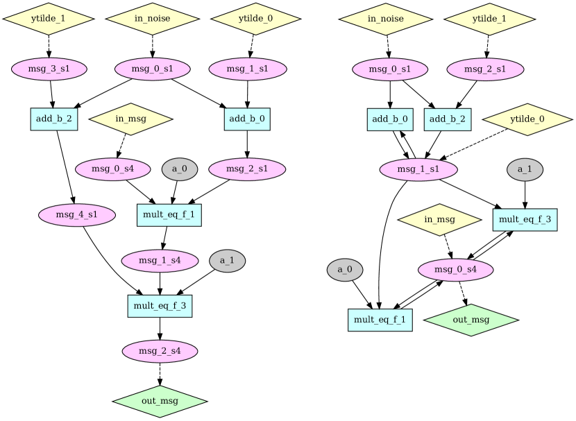
A message update schedule (Fig. 7 left) is first derived from the high level description in Listing 1.
Each message has an identifier assigned, which is mapped to a memory address later on. In a second step, the schedule is optimized to reduce the number of identifiers and hence the size of the message memory (Fig. 7 right). Sequentially, for each output message, the set of identifiers assigned to messages that are no longer needed is considered. A score is computed for each identifier in the set and the output message will be remapped to the identifier having the highest score. The optimized schedule is then compiled into an assembly language program (Listing 2). This program is compressed using the loop instruction and converted into a binary memory image suitable for loading into the processor.
V Implementation Results
As a proof of concept the design was synthesized for the UMC180 CMOS technology for a state matrix size of 4x4 and compared to a state-of-the-art DSP in terms of throughput. As a performance metric the number of message updates on a compound node () per second was chosen because the compound node is the GMP node with the highest computational load. The number of cycles the C66x DSP [10] would take for execution is estimated using the DSPs fixed-point instruction set. According to [11], 768 cycles for the inversion of a complex 4x4 matrix are assumed. The comparison is shown in Table II.
| Processor | FGP (this work) | TI C66x [10] |
|---|---|---|
| CMOS technology [nm] | 180 | 40 |
| Max. freq. [MHz] | 130 | 1250 |
| cycles for compound-node msg. update | 260 | 1076 |
| Normalized max. throughput333Technology scaling to 180nm CMOS assuming . [s] | 2.25 | 1.16 |
The FGP occupies an area of 3.11 mm2 of which 30% are memories, 60% systolic array and 10% datapath and control logic. The maximal clock speed is 130 MHz. The throughput of the C66x is computed at a clock frequency of 1.25GHz [10]. Both the C66x DSP and the FGP operate in fix point number representation and have 64kbit of memory.
Due to the usage of the Faddeev algorithm on the systolic architecture and the usage of a dedicated radix-2 divider, the FGP is able to compute a compound node message update in only 260 cycles. Computing the Schur complement using the Faddeev algorithm is more efficient than computing the inverse and the summands in the Schur complement separately on a conventional DSP instruction set. This leads to a 2x higher throughput for the FGP as can be seen in Table II.
VI Conclusion
The FGP is a promising processing architecture built on the theoretical GMP framework. It is able to run a wide range of signal processing algorithms. The use of a highly configurable systolic array architecture with a dedicated radix-2 divider allows an efficient computation of message updates on a Gaussian factor graph. The presented approach does not only allow to use a low-complexity fixed-point systolic architecture, it also just needs a very simple compilation procedure instead of a complex tool-chain, since the user specifies the message update rules in the high-level representation of the algorithm. In a simple channel estimation example we have shown how the FGP achieves a 2x higher throughput over a state-of-the art DSP. However, neither the presented processor architecture nor it’s applications are fully explored. Future work will include optimizations on architectural level which further exploit the characteristics of GMP, as well as the implementation and performance comparison for other algorithms.
References
- [1] K. Fan, M. Kudlur, G. Dasika, and S. Mahlke, “Bridging the computation gap between programmable processors and hardwired accelerators,” in High Performance Computer Architecture, 2009. HPCA 2009. IEEE 15th Int. Symp. on, 2009, pp. 313–322.
- [2] F. R. Kschischang, B. J. Frey, and H.-A. Loeliger, “Factor graphs and the sum-product algorithm,” Information Theory, IEEE Transactions on, vol. 47, no. 2, pp. 498–519, 2001.
- [3] H.-A. Loeliger, J. Dauwels, J. Hu, S. Korl, L. Ping, and F. R. Kschischang, “The factor graph approach to model-based signal processing,” Proceedings of the IEEE, vol. 95, no. 6, pp. 1295–1322, 2007.
- [4] G. E. Kirkelund, C. N. Manchón, L. P. Christensen, E. Riegler, and B. H. Fleury, “Variational message-passing for joint channel estimation and decoding in MIMO-OFDM,” in Global Telecommunications Conference (GLOBECOM 2010), 2010 IEEE. IEEE, 2010, pp. 1–6.
- [5] Z. Jingshan, J. Dauwels, M. A. Vázquez, and L. Waller, “Efficient gaussian inference algorithms for phase imaging,” Proc. IEEE ICASSP 2012, pp. 25–30.
- [6] H.-L. Jhi, J.-C. Chen, C.-H. Lin, and C.-T. Huang, “A factor-graph-based TOA location estimator,” Wireless Communications, IEEE Transactions on, vol. 11, no. 5, pp. 1764–1773, 2012.
- [7] D. Guo and C.-C. Wang, “Multiuser detection of sparsely spread CDMA,” Selected Areas in Communications, IEEE Journal on, vol. 26, no. 3, pp. 421–431, 2008.
- [8] D. L. Donoho, A. Maleki, and A. Montanari, “Message-passing algorithms for compressed sensing,” Proceedings of the National Academy of Sciences, vol. 106, no. 45, pp. 18 914–18 919, 2009.
- [9] F. Gaston and G. Irwin, “Systolic kalman filtering: an overview,” in Control Theory and Applications, IEE Proceedings D, vol. 137, no. 4. IET, 1990, pp. 235–244.
- [10] R. Damodaran, T. Anderson, S. Agarwala, R. Venkatasubramanian, M. Gill, D. Gopalakrishnan, A. Hill, A. Chachad, D. Balasubramanian, N. Bhoria et al., “A 1.25 GHz 0.8W C66x DSP core in 40nm CMOS,” in VLSI Design (VLSID), 2012 25th Int. Conf. on. IEEE, pp. 286–291.
- [11] M. Yan, B. Feng, and T. Song, “On matrix inversion for LTE MIMO applications using texas instruments floating point DSP,” in Signal Processing (ICSP), 2010 IEEE 10th Int. Conf. on, 2010, pp. 633–636.