Quantum Gates with Phase Stability over Space and Time
Abstract
The performance of a quantum information processor depends on the precise control of phases introduced into the system during quantum gate operations. As the number of operations increases with the complexity of a computation, the phases of gates at different locations and different times must be controlled, which can be challenging for optically-driven operations. We circumvent this issue by demonstrating an entangling gate between two trapped atomic ions that is insensitive to the optical phases of the driving fields, while using a common master reference clock for all coherent qubit operations. Such techniques may be crucial for scaling to large quantum information processors in many physical platforms.
I INTRODUCTION
In a quantum information processor, the control and entanglement of quantum bits is usually accomplished with external electromagnetic fields, whose phase is directly imprinted on the qubits Ladd et al. (2010). Generating large-scale entanglement for applications in quantum information science therefore relies upon the spatial and temporal coherence of phases throughout the system. As the system grows in complexity to many qubits and quantum gate operations, likely requiring a modular architecture Monroe et al. (2014), it will become crucial to control and coordinate the phases between modules and between qubits within a module.
In this paper, we demonstrate the absolute control of qubit phases in both space and time using a collection of trapped atomic ion qubits driven by optical fields. We choose appropriate beam geometries that eliminate the dependence of qubit phases on absolute optical path lengths from the driving field, and we use a common high quality master oscillator as a reference for all operations. These techniques are applicable to many other quantum computing platforms such as NV-centers in diamond Tamarat et al. (2008), optical quantum dots Press et al. (2008), and optical lattices containing neutral atoms Weitenberg et al. (2011).
II EXPERIMENTAL RESULTS
II.1 Single-qubit gates
We consider qubit states with rf or microwave frequency splittings, as opposed to optical qubit splittings which require absolute optical phase stability Häffner et al. (2008). We use qubits encoded in the hyperfine clock states of trapped 171Yb+ atoms and of the manifold with a hyperfine splitting of GHz. Standard photon scattering methods are used for Doppler cooling, state initialization and detection Olmschenk et al. (2007).
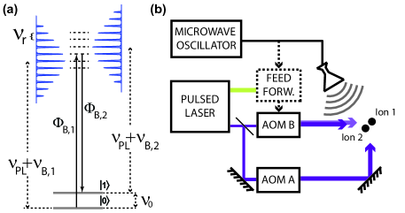
The qubit state can be rotated between and with optical or microwave fields, and we demonstrate phase coherence between these operations by using them sequentially on a qubit. Copropagating stimulated Raman transitions Wineland et al. (1998) are driven with optical frequency combs Hayes et al. (2010) generated by a mode-locked 355 nm ( THz) pulsed laser with repetition rate . An acousto-optic modulator (AOM B) is driven with frequencies , that are adjusted to bring the beat-note between Raman beams on resonance with the qubit hyperfine splitting (Fig. 1a):
| (1) |
where is an integer. Due to atomic selection rules, transitions are only driven when the two beams have the same circular polarization Olmschenk et al. (2007). Since these beams from AOM B are nominally copropagating, drifts of the optical path length result in negligible phase errors on the qubit.
In order to stabilize the beat-note frequency to an external master oscillator, we feed-forward fluctuations in the measured repetition rate of the pulsed laser to downstream AOM B (see Fig. 1b) Islam et al. (2014). This feed-forward technique may be more useful than directly stabilizing the laser cavity length, because of the limited bandwidth of mechanical transducers and the possible inaccessibility of the laser cavity.
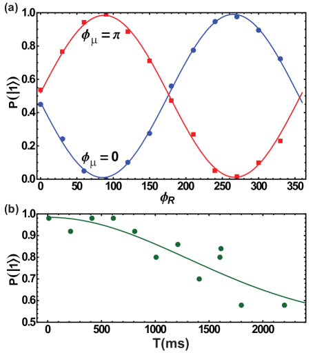
We use the master oscillator as a reference clock for microwave and Raman rotations. In order to maintain phase coherence between qubit operations over long time scales, we use an arbitrary waveform generator (AWG) that provides signals at multiple frequencies with well-defined phase relations and bridges frequency differences between the master oscillator and qubit levels. We verify coherence between microwave and Raman rotations by performing a Ramsey experiment and observe a coherence time of 1.8 seconds as shown in Fig. 2. With this scheme, microwaves can be used for global qubit rotations, while focused Raman beams can address individual qubits in a long chain for single qubit rotations.
II.2 Multi-qubit entangling gates
Entangling trapped atomic qubits through their Coulomb interaction requires external field gradients that provide state-dependent forces. The absolute phase and amplitude of microwave or rf fields can easily be controlled for this purpose, but generating sufficiently high field gradients requires specialized trap geometries and high currents Ospelkaus et al. (2011). Instead, optical fields can be used where non-copropagating Raman beams are required to generate large field gradients Leibfried et al. (2003a); Cirac and Zoller (1995); Sørensen and Mølmer (2000), however, relative path length fluctuations can imprint unknown phases on the qubits.
Here we utilize a particular geometry of non-copropagating beams to realize gates insensitive to the optical phase of the laser beams. Such gates have been demonstrated on magnetic field sensitive states Leibfried et al. (2003b); however, their susceptibility to magnetic field noise results in shorter coherence times compared to clock states. Phase insensitive gates on clock states have been realized with CW lasers to provide a state-dependent force by addressing both red and blue sideband transitions; and respectively where is the vibrational eigenstate of the ions in a harmonic trap potential Wineland et al. (1998); Haljan et al. (2005a); Lee et al. (2005). This has also been accomplished by simultaneously driving a carrier, , and a single sideband transition Bermudez et al. (2012); Tan et al. (2013). However, this approach requires very large carrier Rabi frequencies to prevent additional gate errors Lemmer et al. (2013).
The use of CW lasers is technically difficult for systems with qubit splittings more than a few GHz since it requires phase-locking two monochromatic sources or the use of modulators with limited bandwidths. Alternatively, the large bandwidths of ultrafast laser pulses easily spans such splittings Hayes et al. (2010). Here, we experimentally demonstrate a phase insensitive gate on the clock states of two qubits, where two sidebands of a vibrational mode are excited simultaneously by an optical frequency comb generated from a pulsed laser. The beat-note of the frequency combs is locked to the master oscillator to provide phase coherence between quantum gates performed over long time scales and at different locations while maintaining phase coherence of the entangling gates with microwave and copropagating Raman rotations. The techniques demonstrated here can also be used to maintain long coherence times on simultaneous carrier and single sideband gates Bermudez et al. (2012), where the carrier transition is induced either by microwaves or Raman beams.
II.2.1 Generation of gate frequencies
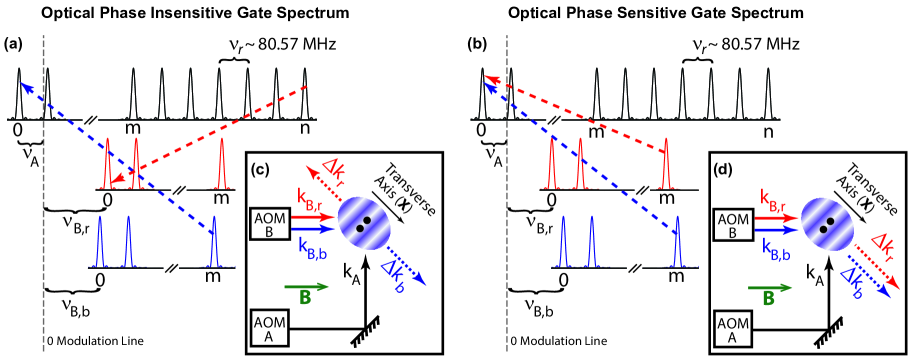
Two-qubit entanglement is generated following the Mølmer-Sørensen protocol Sørensen and Mølmer (2000); Milburn et al. (2000); Solano et al. (1999), in which optical driving fields are tuned near the red and blue sidebands of a vibrational mode. In order to obtain the desired optical spectra for the phase insensitive gate Hayes et al. (2010); Islam et al. (2014), each Raman beam passes through AOMs A and B of Fig. 1b to generate a relative frequency offset () and allow phase control of the various frequency elements (Fig. 3a):
| (2) |
where and are integers, is the frequency of the vibrational mode of interest and is the symmetric detuning from this mode. Note that and are applied to the same AOM, resulting in two nearly copropagating beams. With 2.5 MHz, = 10 kHz, 80.57 MHz and = 77.5 MHz, these equations can be satisfied by , 173.4 MHz and , 160.0 MHz.
II.2.2 The gate phase
After application of the optical fields for the gate time, the collective motion of the ions factors and the qubit states evolve as Sørensen and Mølmer (2000); Lee et al. (2005):
| (3) |
The gate phase is with individual “spin” phases:
| (4) |
Here , are the phases associated with the red and blue sideband transitions and is the position of the ion Lee et al. (2005). The two optical field pairs address the red (, ) and blue (, ) vibrational sidebands. To drive the red sideband using a mode-locked pulsed laser, a photon is absorbed from the comb tooth and emitted into the comb tooth. The opposite process takes place for the blue sideband, resulting in and . Since the vectors point in opposite directions, , small fluctuations of the optical path length cancel to a high degree, leaving the gate phase unchanged (Fig. 3c,d). The gate phase retains sensitivity to the rf signals applied to the AOMs and may be modified by modulating the applied phases and to set and to any desired value.
II.2.3 The motional phase
During an entangling gate, the motion correlated with particular eigenstates of the two qubits are separated in phase space with application of a state-dependent force. Without loss of generality, we consider a single collective mode of motion, and the relative displacements are described by the motional phase Lee et al. (2005)
| (5) |
In the optical “phase insensitive” geometry Lee et al. (2005), the optical path length dependence of is transferred to ; however, the phase dependence of on the optical path is identical for the two ions and thus global fluctuations do not affect the entangling gate Haljan et al. (2005b).
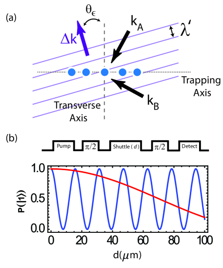
The static motional phase difference between two ions determines the gate time Lee et al. (2005) to produce the evolution of Eq. 3. If axial vibrational modes are used, the distance between the ions must be carefully controlled and the gate fidelity becomes susceptible to changes in ion spacing Haljan et al. (2005a); Tan et al. (2013). Moreover, entangling longer ion chains becomes problematic as the distance between ions may vary along the chain. These issues are circumvented by using the transverse modes for gate operations Zhu et al. (2006). Since the phase fronts created by the optical fields are ideally uniform across the trapping axis when the transverse modes are addressed, the motional phase is the same for all ions (Fig. 3c,d). However, misalignment between the vectors and the transverse axis by an angle would introduce a motional phase difference sin between the ions where is the ion separation (Fig. 4a).
Optical fields can be aligned to better than 0.05∘ by measuring the variation of the resonant photon scattering rate across the ions due to the AC Stark shift induced by the optical field gradient Britton et al. (2012). Since this technique relies on obtaining sufficiently large AC Stark shifts, it requires tuning the Raman beam frequencies close to the Doppler cooling transition which may be impractical with pulsed lasers due to their large bandwidths and limited tuning capabilities. Furthermore, achieving good alignment relies on using large ion crystals; while an ion crystal diameter of hundreds of m can be maintained in Penning traps Britton et al. (2012), it can be challenging to hold similar length ion crystals in rf Paul traps. An alternative technique incorporates shuttling and utilizes the phase differences of non-copropagating Raman rotations at different points along the trapping axis. The phase differences could be directly measured using a single ion for the alignment of the Raman beams with respect to the transverse axis (see Fig. 4b). Although not implemented in this work, high accuracy alignment can be achieved in principle with this technique.
II.2.4 Phase coherence of the gate
Long term phase coherence can be maintained with an extension of the beat-note stabilization technique by feeding forward changes in to (see Appendix for details). Even in the absence of drifts in , this technique can be used to synchronize pulsed laser operations with a master oscillator to maintain phase coherence with microwaves or operations by other pulsed lasers in the system. A free-running frequency source can be used to generate the AOM frequency as cancels in the gate phase, . In order to maintain phase coherence between entangling gates, copropagating Raman transitions and microwave rotations that have differing drive frequencies, an AWG may be used for these operations rather than free-running frequency sources, where phase relations between different frequency components must be tracked resulting in increased system overhead.
II.2.5 Characterization of the system
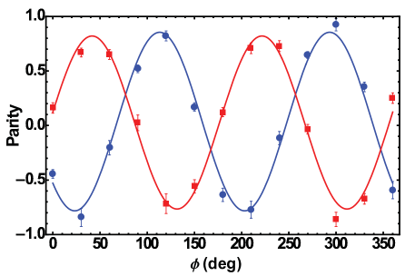
We characterize the optical phase sensitivity of entangling gates by measuring the fidelity of various entangled states through extraction of the density matrix elements of the prepared state Sackett et al. (2000); we measure the populations along with the parity contrast in order to extract a fidelity of 0.86. The parity contrast is obtained by scanning the phase of the analysis microwave and Raman pulses after the entangling gate (Fig. 5). For the gate, Walsh modulation is implemented to suppress detuning and timing errors Hayes et al. (2012). The imperfect fidelity is not a limitation of the phase insensitive gate; we observe similar fidelities using a phase sensitive geometry (Fig. 3b,d) for the gate. Thermal populations of the motional states contributes an error of % and histogram fitting of two ion combined brightness for parity measurements contributes an additional % Hayes et al. (2010).
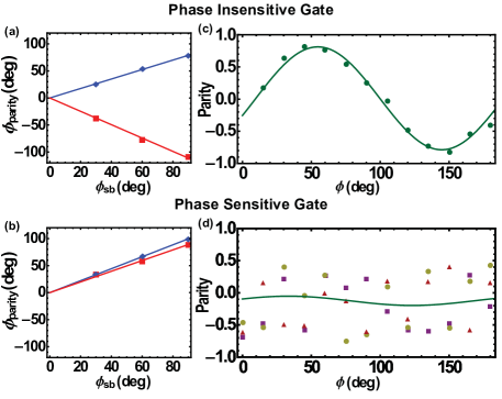
We further characterize and compare the phase insensitive and sensitive gates by directly measuring how the phases of the driving fields are imprinted on the entangled states. In the case of a phase insensitive gate, the phase of the red and blue sideband frequencies modify the gate phase with opposite signs, . The phase of the parity oscillation shift in opposite directions for red and blue sideband phase shifts. In the phase sensitive case, , which results in the parity phase moving in the same direction for both sideband phase shifts (Fig 6a,b). To simulate a relative optical path length change at the ion position, a random phase is added to both sidebands driven by the AWG. The phase insensitive gate parity is not affected by this randomization process, while loss of contrast is observed for the phase sensitive gate as expected (Fig 6c,d).
Lastly, we test the stability of our system over long time scales by monitoring the phase of parity oscillations following analysis of the phase insensitive gate by a microwave pulse. We observe phase fluctuations of <8∘ of the parity curve over a period of 24 hours. Therefore, once relative phase relations have been characterized between different quantum operations sharing the same master oscillator, regular monitoring of these phases is not necessary. This long term stability will be necessary for long computations.
III OUTLOOK: IMPLICATIONS TOWARDS SCALABILITY
The techniques presented here can be useful in a large scale modular quantum processor architecture Monroe et al. (2014); Hucul et al. (2014). In this proposal, modules hold ion chains of manageable sizes and entanglement within a module is generated with mutual Coulomb interactions while photonic interfaces Duan et al. (2006); Moehring et al. (2007) establish connections between separate modules. As shown here, the use of a common master oscillator for all quantum operations and insensitivity to optical path length fluctuations can be implemented to realize phase coherent operations across this architecture.
In the shuttling model proposed for a large-scale quantum processor, ions are transported between various trapping regions in order to perform specific operations Kielpinski et al. (2002). These phase stabilization techniques might be beneficial in this model as it is important to maintain phase coherence between the operations performed at different regions of the processor and at different times. Moreover, coupling to transverse modes for multi-qubit gate operations instead of axial modes would eliminate errors that might stem from small changes in ion separation after shutting between regions. Finally, the complexity of the device electrode structure might be reduced as it is not necessary to keep a uniform ion spacing with the use of transverse modes Zhu et al. (2006).
IV SUMMARY
In summary, we demonstrate long term coherence between various qubit operations utilizing optical and microwave fields referenced to a single master oscillator. The setup presented here effectively eliminates any optical path length related phase drifts from these operations, obviating the need for optical interferometric stability in a quantum system. Moreover, the use of a master oscillator as a reference provides coherence between qubit operations done at different times and at different locations which is central to realizing a large-scale, distributed and modular quantum computer. By using a stable master oscillator, the long coherence times of trapped atomic ions can be harnessed effectively to execute many subsequent operations on the system and preserve quantum information for long times while operations are performed on other qubits.
Acknowledgements.
This work was supported by the Intelligence Advanced Research Projects Activity, the Army Research Office MURI Program on Hybrid Quantum Optical Circuits, Defense Advanced Research Projects Agency SPARQC and the NSF Physics Frontier Center at JQI.*
Appendix A Phase Stabilization Circuit
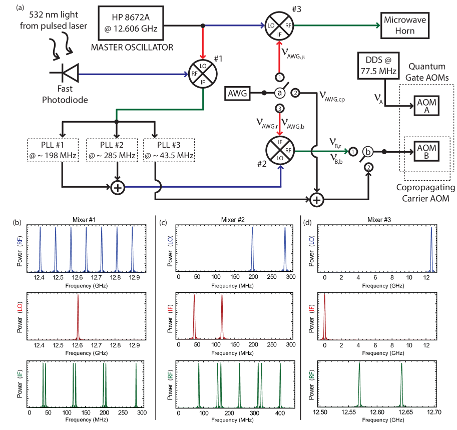
Cavity length changes cause drifts in the repetition rate of the pulsed laser, , which result in fluctuations of the separation between comb teeth (Fig. 3a,b) and thus phase and frequency drifts that can cause gate errors. Since two different comb tooth solutions are used to drive the gate (Eq. 2), separate phase locked loops (PLLs) are necessary to lock the and frequency splittings between the comb teeth (see Ref. Islam et al. (2014) for details on the PLL). Moreover, phase coherence between quantum operations is needed for full qubit control and can be achieved with the circuit given in Fig. 7. By adding a third PLL, coherent copropagating Raman carrier transitions can also be incorporated.
In order to monitor and feed-forward the repetition rate drift , the signal from the fast photodiode is mixed with the master oscillator, GHz, to produce beat-notes. The PLLs output a signal that is phase locked with the relevant input beat-note frequencies:
| (6) |
where and in this experiment. These output signals are mixed with the AWG signal to provide driving frequencies for AOM B:
| (7) |
Both frequencies should be within the bandwidth of AOM B for optimal diffraction efficiency. Inserting Eq. 6 and 7 in Eq. 2 with MHz, the AWG frequencies for driving the entangling gate are:
| (8) |
with MHz, MHz. As can be seen from Eq. 8, feed-forward to the PLLs not only eliminates sensitivity to but also utilizes the master oscillator as a reference for qubit transitions. To generate microwave rotations that are phase coherent with the Raman transitions, the master oscillator is mixed with the AWG, , and sent to a microwave horn. The achievable coherence time between quantum operations with this technique can be increased by using oscillators with lower phase noise.
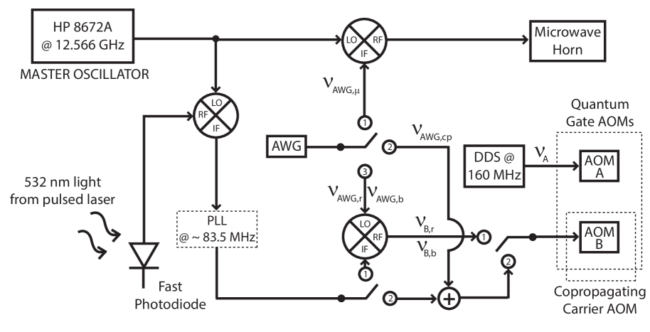
It is also possible to realize the set of operations presented in this paper by using only one comb tooth solution, , with MHz, 169.2 MHz and 155.7 MHz. Through the appropriate use of mixers, a single PLL can provide the correct feed-forward to lock these two Raman transitions to the master oscillator (Fig. 8). This approach has the advantage of using fewer electronic elements.
In Fig. 7 and 8, AOM B is used for both entangling gates and copropagating Raman rotations for optimal use of resources. Since the AOMs only work efficiently in a certain rf range, conversion of the rf signals might be necessary to obtain high efficiency beam diffraction for the copropagating Raman rotations. This can be achieved by mixing the rf signals with a DDS to convert signals to the correct frequency range (not shown in Fig. 7 and 8 for simplicity). As this mixing will result in a common-mode phase and frequency change in both AWG and PLL signals, the DDS signal has no effect on the phase of the rotations hence a free-running source can be used.
References
- Ladd et al. (2010) T. D. Ladd et al., Nature 464, 45 (2010).
- Monroe et al. (2014) C. Monroe et al., Phys. Rev. A 89, 022317 (2014).
- Tamarat et al. (2008) P. Tamarat et al., New J. Phys. 10, 045004 (2008).
- Press et al. (2008) D. Press et al., Nature 456, 218 (2008).
- Weitenberg et al. (2011) C. Weitenberg et al., Nature 471, 319 (2011).
- Häffner et al. (2008) H. Häffner, C. F. Roos, and R. Blatt, Phys. Rep. 469, 155 (2008).
- Olmschenk et al. (2007) S. Olmschenk et al., Phys. Rev. A 76, 052314 (2007).
- Wineland et al. (1998) D. J. Wineland et al., J. Res. Nat. Inst. Stand. Tech. 103, 259 (1998).
- Hayes et al. (2010) D. Hayes et al., Phys. Rev. Lett. 104, 140501 (2010).
- Islam et al. (2014) R. Islam et al., Opt. Lett. 39, 3238 (2014).
- Ospelkaus et al. (2011) C. Ospelkaus et al., Nature 476, 181 (2011).
- Leibfried et al. (2003a) D. Leibfried et al., Rev. Mod. Phys. 75, 281 (2003a).
- Cirac and Zoller (1995) J. I. Cirac and P. Zoller, Phys. Rev. Lett. 74, 4091 (1995).
- Sørensen and Mølmer (2000) A. Sørensen and K. Mølmer, Phys. Rev. A 62, 022311 (2000).
- Leibfried et al. (2003b) D. Leibfried et al., Nature 422, 412 (2003b).
- Haljan et al. (2005a) P. C. Haljan et al., Phys. Rev. A 72, 062316 (2005a).
- Lee et al. (2005) P. J. Lee et al., J.Opt. B 7, 371 (2005).
- Bermudez et al. (2012) A. Bermudez, P. O. Schmidt, M. B. Plenio, and A. Retzker, Phys. Rev. A 85, 040302 (2012).
- Tan et al. (2013) T. R. Tan et al., Phys. Rev. Lett. 110, 263002 (2013).
- Lemmer et al. (2013) A. Lemmer, A. Bermudez, and M. B. Plenio, New J. Phys. 15, 083001 (2013).
- Milburn et al. (2000) G. J. Milburn, S. Schneider, and D. F. V. James, Fortschr. Phys. 48, 801 (2000).
- Solano et al. (1999) E. Solano, R. L. de Matos Filho, and N. Zagury, Phys. Rev. A 59, 2539(R) (1999).
- Haljan et al. (2005b) P. C. Haljan, K. A. Brickman, L. Deslauriers, P. J. Lee, and C. Monroe, Phys. Rev. Lett. 94, 153602 (2005b).
- Zhu et al. (2006) S.-L. Zhu, C. Monroe, and L.-M. Duan, Phys. Rev. Lett. 97, 050505 (2006).
- Britton et al. (2012) J. W. Britton et al., Nature 484, 489 (2012).
- Sackett et al. (2000) C. A. Sackett et al., Nature 404, 256 (2000).
- Hayes et al. (2012) D. Hayes et al., Phys. Rev. Lett. 109, 020503 (2012).
- Hucul et al. (2014) D. Hucul et al., arXiv:1403.3696 (2014).
- Duan et al. (2006) L.-M. Duan et al., Phys. Rev. A 73, 062324 (2006).
- Moehring et al. (2007) D. L. Moehring et al., Nature 449, 68 (2007).
- Kielpinski et al. (2002) D. Kielpinski, C. Monroe, and D. J. Wineland, Nature 417, 709 (2002).