Electronic control of the spin-wave damping in a magnetic insulator
Abstract
It is demonstrated that the decay time of spin-wave modes existing in a magnetic insulator can be reduced or enhanced by injecting an in-plane dc current, , in an adjacent normal metal with strong spin-orbit interaction. The demonstration rests upon the measurement of the ferromagnetic resonance linewidth as a function of in a 5 m diameter YIG(20nm)|Pt(7nm) disk using a magnetic resonance force microscope (MRFM). Complete compensation of the damping of the fundamental mode is obtained for a current density of , in agreement with theoretical predictions. At this critical threshold the MRFM detects a small change of static magnetization, a behavior consistent with the onset of an auto-oscillation regime.
The spin-orbit interaction (SOI) valenzuela06 ; Jungwirth2012 ; manchon08 has been recently shown to be an interesting and useful addition in the field of spintronics. This subject capitalizes on adjoining a strong SOI normal metal next to a thin magnetic layer thiaville12 . The SOI converts a charge current, , to a spin current, , with an efficiency parametrized by , the spin Hall angle dyakonov71 ; hirsch99 . Recently, it was demonstrated experimentally that the spin current produced in this way can switch the magnetization in a dot miron11 ; liu12 or can partially compensate the damping ando08a ; liu11 ; demidov11d , allowing the lifetime of propagating spin-waves an14 to be increased beyond their natural decay time, . These two effects open potential applications in storage devices and in microwave signal processing.
The effect is based on the fact that the spin current exerts a torque on the magnetization, corresponding to an effective damping , where is the thickness of the magnetic layer, its spontaneous magnetization, and the gyromagnetic ratio. In the case of metallic ferromagnets demidov12 ; liu12b ; liu13 , it was established that can fully compensate the natural damping at a critical spin current , which determines the onset of auto-oscillation of the magnetization:
| (1) |
An important benefit of the SOI is that and are linked through a cross-product, allowing a charge current flowing in-plane to produce a spin current flowing out-of-plane. Hence it enables the transfer of spin angular momentum to non-metallic materials and in particular to insulating oxides, which offer improved performance compared to their metallic counterparts. Among all oxides, Yttrium Iron Garnet (YIG) holds a special place for having the lowest known spin-wave (SW) damping factor. In 2010, Kajiwara et al. reported on the efficient transmission of spin current through the YIG|Pt interface kajiwara10 . It was shown that produced by the excitation of ferromagnetic resonance (FMR) in YIG can cross the YIG|Pt interface and be converted into in Pt through the inverse spin Hall effect (ISHE). This finding was reproduced in numerous experimental works sandweg10 ; kurebayashi11 ; vilela-leao11 ; chumak12 ; hahn13 ; kelly13 ; wang13 . In the same paper, the reciprocal effect was also reported as produced in Pt by the direct spin Hall effect (SHE) could be transferred to the 1.3 m thick YIG, resulting in damping compensation. However, attempts to directly measure the expected change of the resonance linewidth of YIG as a function of the dc current have so far failed hahn13 ; kelly13 111Indirect observation through small changes of the SW amplitude wang11 ; padron-hernandez11 cannot be conclusive due to the sensitivity to thermal effects.. This is raising fundamental questions about the reciprocity of the spin transparency, , of the interface between a metal and a magnetic insulator. This coefficient enters in the ratio between in Pt and in YIG through:
| (2) |
where is the electron charge and the reduced Planck constant. depends on the transport characteristics of the normal metal as well as on the spin-mixing conductance , which parametrizes the scattering of the spin angular momentum at the YIG|Pt interface chen13 .
At the heart of this debate lies the exact value of the threshold current. The lack of visible effects reported in Refs.hahn13 ; kelly13 , although inconsistent with kajiwara10 , is coherent with the estimation of the threshold current of A.m-2 using Eqs.(1) and (2) and typical parameters for the materials xiao12 . This theoretical current density is at least one order of magnitude larger than the maximum that could be injected in the Pt so far. Importantly, the previous reported experiments were performed on large (millimeter sized) structures, where many nearly degenerate SW modes compete for feeding from the same dc source of angular momentum, a phenomenon that could become self-limiting and prevent the onset of auto-oscillations demidov11d . To isolate a single candidate mode, we have recently reduced the lateral dimensions of the YIG pattern, as quantization results in increased frequency gaps between the dynamical modes hahn14 . This requires to grow very thin films of high quality YIG sun12 ; althammer13 ; wang13 ; pirro14 . Benefiting from our progress in the epitaxial growth of YIG films by pulsed laser deposition (PLD) kelly13 , we propose to study the FMR linewidth as a function of the dc current in a micron-size YIG|Pt disk.
FIG.1 shows a schematic of the experimental setup. A YIG|Pt disk of m in diameter is connected to two Au contact electrodes (see the microscopy image) across which a positive voltage generates a current flow along the -direction. The microdisk is patterned out of a 20 nm thick epitaxial YIG film with a 7 nm thick Pt layer sputtered on top. The YIG and Pt layers have been fully characterized in previous studies kelly13 ; rojas14 . Their characteristics are reported in Table 1.
| Pt | (nm) | (.m-1) | (nm) | |
|---|---|---|---|---|
| 7 | 3.5 | 0.056 | ||
| YIG | (nm) | (G) | (rad.s-1.G-1) | |
| 20 |
The sample is mounted inside a room temperature magnetic resonance force microscope (MRFM) which detects the SW absorption spectrum mechanically zhang96 ; klein08 ; chia12 . The excitation is provided by a stripline (not shown in the sketches of FIG.1) generating a linearly polarized microwave field along the -direction. The detection is based on monitoring the deflection of a mechanical cantilever with a magnetic Fe particle affixed to its tip, coupled dipolarly to the sample. The FMR spectrum is obtained by recording the vibration amplitude of the cantilever while scanning the external bias magnetic field, , at constant microwave excitation frequency, 222When FMR conditions are met, the precession angle increases and in consequence the static magnetization (projection along the precession axis) decreases, hereby exciting mechanically the cantilever.. The MRFM is placed between the poles of an electromagnet, generating a uniform magnetic field, , which can be set along or (i.e., perpendicularly to both and ).
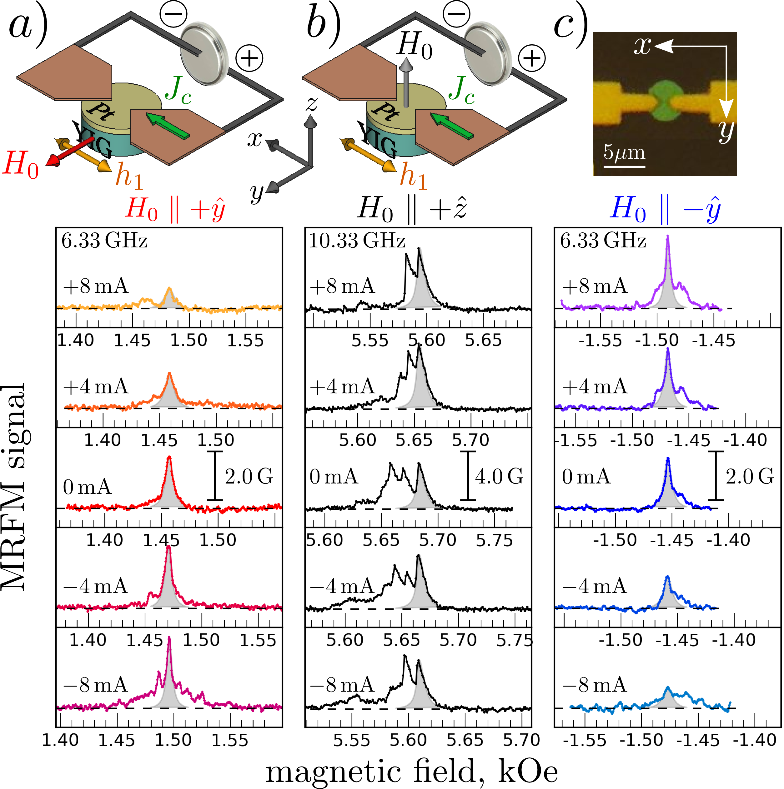
We start by measuring the effect of a dc current, , on the FMR spectra when the disk is magnetized in-plane by a magnetic field along the -direction (positive field). The spectra recorded at GHz are shown in FIG.1a in red tones. The middle row shows the absorption at zero current. The MRFM signal corresponds to a variation of the static magnetization of about 2 G, i.e., a precession cone of 2.5∘. As the the electrical current is varied, we observe very clearly a change of the linewidth. At negative current, the linewidth decreases, to reach about half the initial value at mA. This decrease is strong enough so that the individual modes can be resolved spectroscopically within the main peak. Concomitantly the amplitude of the MRFM signal increases. The opposite behavior is observed when the current polarity is reversed. At positive current, the linewidth increases to reach about twice the initial value at mA, and the amplitude of the signal decreases.
mA is the maximum current that we have injected in our sample to avoid irreversible effects. We estimate from the Pt resistance, the sample temperature to be C at the maximum current. This Joule heating reduces at a rate of G/K, which results in an even shift of the resonance field towards higher field 333Actually, the resonance peak shifts in field due to both the linear ( Oe/mA) and quadratic ( Oe/mA2) contributions in current of Oersted field and Joule heating, respectively..
In FIG.1b, we show the FMR spectra at GHz in the perpendicular geometry, i.e., is along . In contrast to the previous case, the linewidth does not change with current. This is expected as no net spin transfer torque is exerted by the spin current on the precessing magnetization in this configuration. Note that due to Joule heating, the spectrum now shifts towards lower field due to the decrease of as the current increases.
We now come back to the in-plane geometry, but this time, the magnetic field is reversed compared to FIG.1a, i.e., applied along (negative field). The corresponding spectra are presented in FIG.1c using blue tones. As expected for the symmetry of the SHE, the observed behavior is inverted with respect to FIG.1a: a positive (negative) current now reduces (broadens) the linewidth.
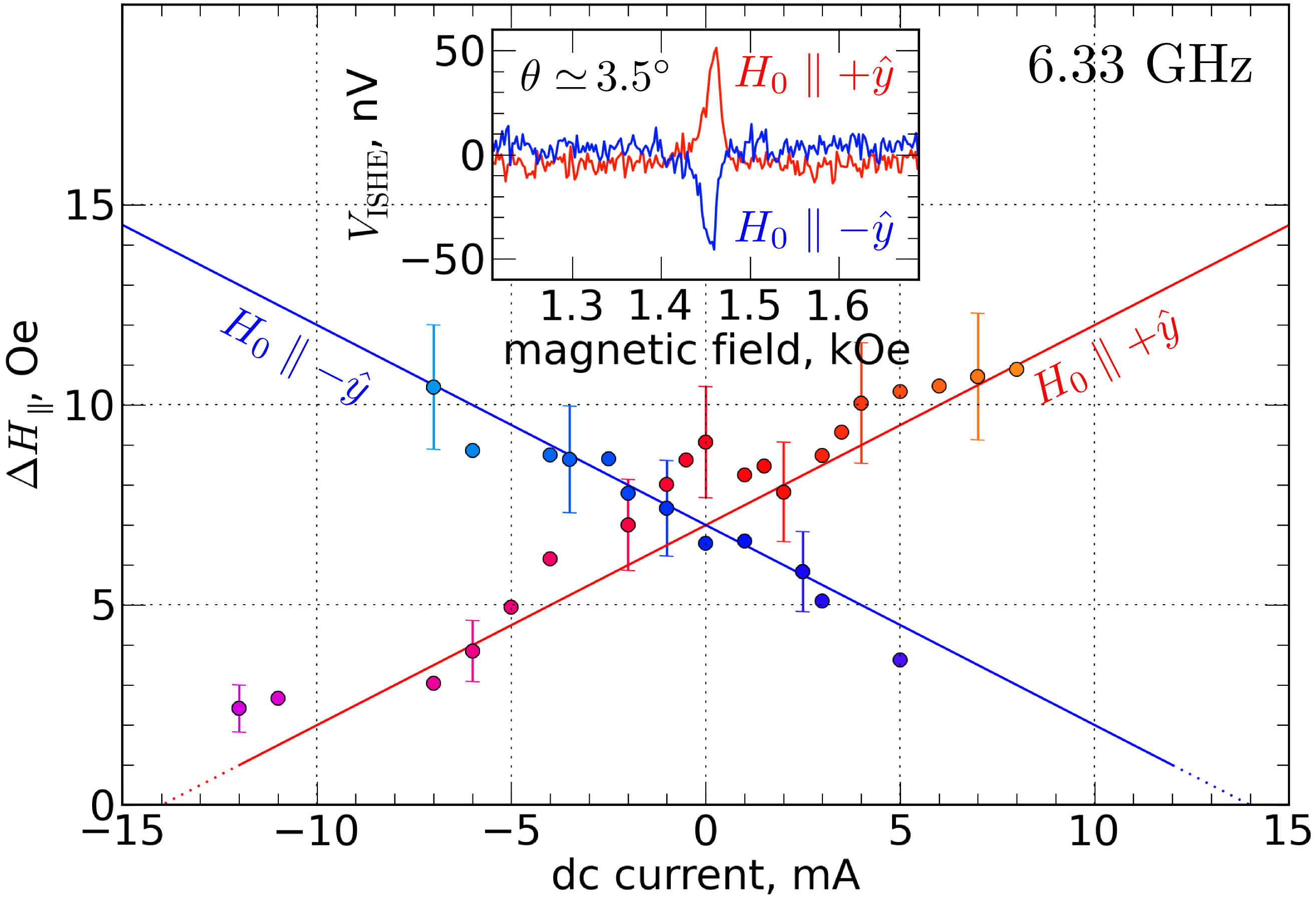
We report in FIG.2 the values of , the full linewidth measured in the in-plane geometry, as a function of current. The data points follow approximately a straight line, whose slope Oe/mA reverses with the direction of along and whose intercept with the abscissa axis occurs at mA. Moreover, we emphasize that the variation of linewidth covers about a factor five on the full range of current explored.
The inset of FIG.2 shows the inverse spin Hall voltage measured at mA and GHz. This voltage results from the spin current produced by spin pumping from YIG to Pt and its subsequent conversion into charge current by ISHE kajiwara10 . Its sign changes with the direction of the bias magnetic field, as shown by the blue and red spectra. This observation confirms that a spin current can flow from YIG to Pt and that damping reduction occurs for a current polarity corresponding to a negative product of and .
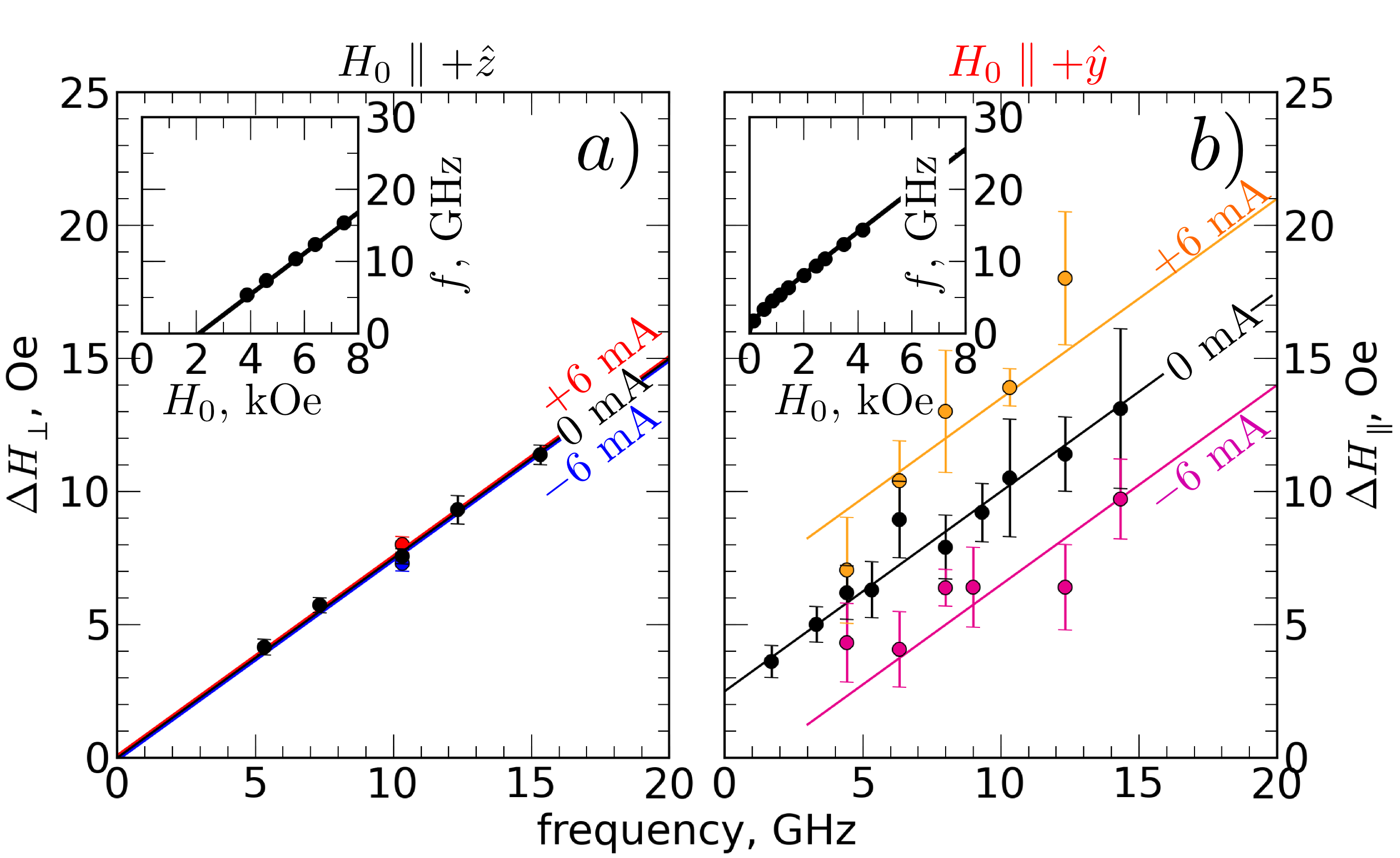
To gain more insight into these results, we now analyze the frequency dependence of the full linewidth at half maximum for three values of dc current (0, mA) for both the out-of-plane and in-plane geometries. We start with the out-of-plane data, plotted in FIG.3a. The dispersion relation displayed in the inset follows the Kittel law, , where is an effective demagnetizing factor close to 1 kakazei04 ; naletov11 . The linewidth increases linearly with frequency along a line that intercepts the origin, a signature that the resonance is homogeneously broadened hahn14 . In this geometry, the Gilbert damping coefficient is simply and the reaxation time . We also report on this figure the fact that at 10.33 GHz, 7 Oe is independent of the current (see FIG.1b).
The damping found in our YIG|Pt microdisk is significantly larger than the one measured in the bare YIG film (cf. Table 1). This difference is due to the spin pumping effect, and enables to determine the spin-mixing conductance of our YIG|Pt interface through tserkovnyak05 ; heinrich11 :
| (3) |
where is the quantum of conductance. The measured increase of almost for the damping corresponds to , in agreement with a previous determination made on similar YIG|Pt nanodisks hahn14 . This value allows us to estimate the spin transparency of our interface chen13 , , where is the Pt conductivity and its spin-diffusion length. Moreover, the spin-mixing conductance can be used to analyze quantitatively the dc ISHE voltage produced at resonance mosendz10 ; castel12a ; hahn13 . Using the parameters of Table 1 and the value of , we find that the 50 nV voltage measured in the inset of FIG.2 is produced by an angle of precession , which lies in the expected range.
We now turn to the in-plane data, presented in FIG.3b. The dispersion relation plotted in the inset follows the Kittel law . In this case, . For mA the slope of the linewidth vs. frequency is exactly the same as that in the perpendicular direction . For this geometry, however, the line does not intercept the origin, indicating a finite amount of inhomogeneous broadening Oe, i.e, the presence of several modes within the resonance line. Setting to mA shifts by Oe independently of the frequency, which is consistent with the rate of 0.5 Oe/mA reported at 6.33 GHz in FIG.2. In fact, in the presence of the effective damping , the linewidth of the resonance line varies as
| (4) |
This expression is valid when , i.e., at large enough field or frequency (see inset of FIG.3b). It describes appropriately the experimental data on the whole frequency range measured.
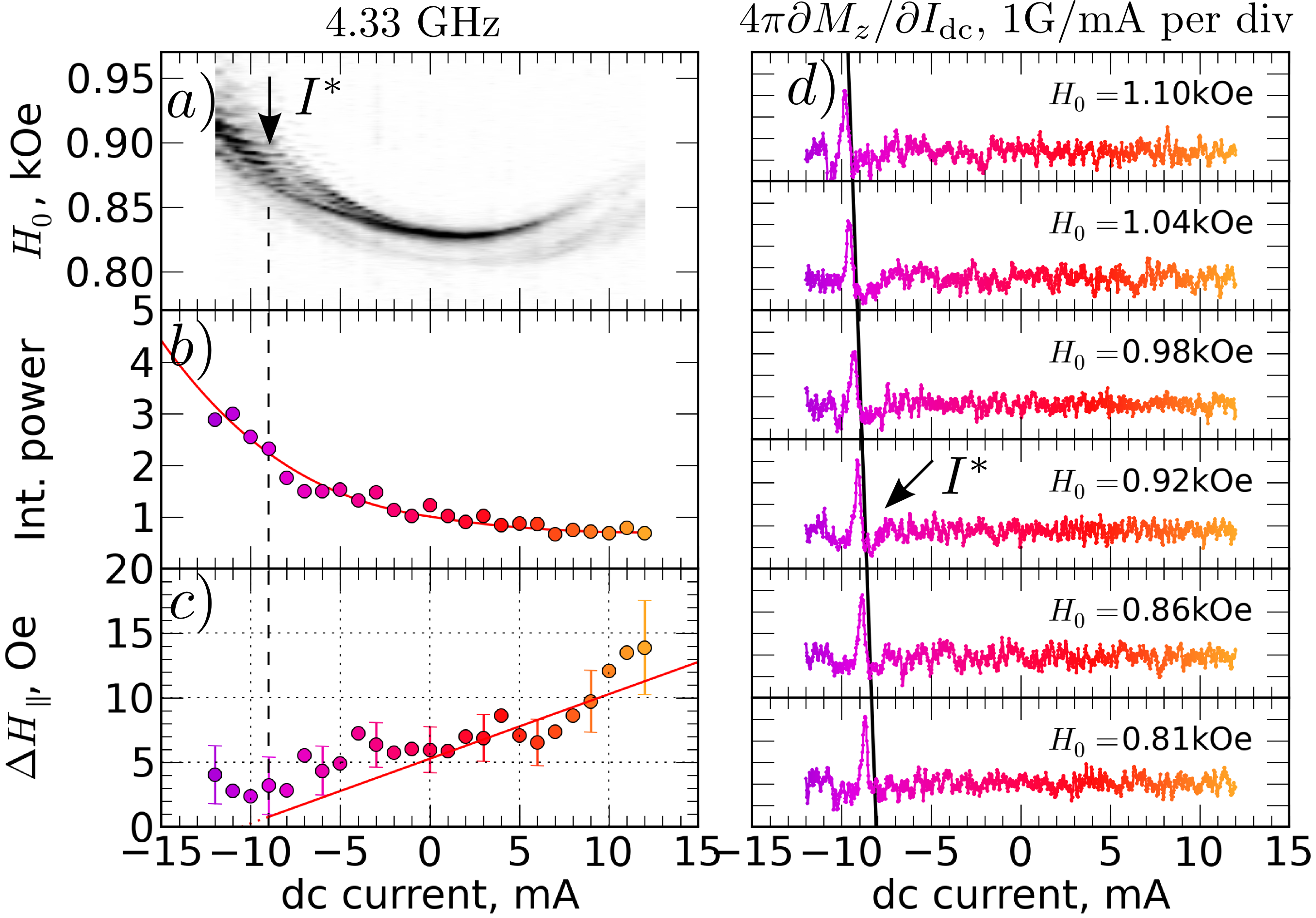
In order to investigate the autonomous dynamics of the YIG layer and exceed the compensation current, , we now perform measurements at lower excitation frequency, where the threshold current is estimated below 12 mA. In FIG.4a, we present a density plot of the MRFM spectra acquired at 4.33 GHz as a function of the in-plane magnetic field and through the Pt. The measured signal is clearly asymmetric in . At positive current, it broadens and its amplitude decreases, almost disappearing above mA, whereas at negative current, it becomes narrower and the amplitude is maximal at mA.
The power integrated over the full field range normalized by its value at 0 mA and the linewidth variation vs. are plotted in FIGs.4b and 4c, respectively. The normalized integrated power varies by a factor of five from mA to mA following an inverse law on (see continuous line), which is consistent with the spin transfer effect demidov11d ; hamadeh12 . The linewidth varies roughly linearly with : it increases from 6 Oe at 0 mA up to 14 Oe at mA and it reaches a minimum value close to 2 Oe between and mA. It is interesting to note that this happens in a region of the density plot where the evolution of the signal displays some kind of discontinuity, with the appearance of several high amplitude peaks in the spectrum (see arrow in FIG.4a). We tentatively ascribe this feature to the onset of auto-oscillations in the YIG layer, namely, one or several dynamical modes have their relaxation compensated by the injected spin current and are destabilized kajiwara10 .
To confirm this hypothesis, we present in FIG.4d results of an experiment where no rf excitation is applied to the system. Here, the dc current is modulated at the MRFM cantilever frequency by mA and the induced is probed as a function of . This experiment thus provides a differential measurement of the magnetization (in analogy with measurements in transport experiments). At kOe, a peak in is measured around mA. It corresponds to a variation of G, i.e., a change of the angle of precession by induced by the modulation of current. Moreover, this narrow peak observed in shifts linearly in dc current with the applied magnetic field, from mA at 0.81 kOe to mA at 1.1 kOe (see the continuous straight line in FIG.4d), in agreement with the expected behavior of the threshold current Eq.(1).
Hence, FIG.4 presents a set of data consistent with the determination of a critical current of mA at kOe, corresponding to A.m-2, in agreement with the value of A.m-2 expected from Eqs.(1) and (2) and the parameters of our system. Nevertheless, the destabilization of dynamical modes is rather small, as the jump of resonance field at (due to reduction of the magnetization) does not exceed the linewidth. We suspect that in our YIGPt microdisk, the splitting of modes is not sufficient to prevent nonlinear interactions that limit the amplitude of auto-oscillations demidov11d . In order to favor larger auto-oscillation amplitudes, YIG structures that are even more confined laterally (below 1 m) should be used hahn14 , or one should excite a bullet mode demidov12 .
In conclusion, we have demonstrated that it is possible to control electronically the SW damping in a YIG microdisk. Extending this result to one-dimensional SW guide duan14 will offer great prospect in the emerging field of magnonics kruglyak10a ; serga10 , whose aim is to investigate the manipulation of SW and their quanta – magnons – with the benefice of combining ultra-low energy consumption and compactness. To improve the magnonic paradigm, a solution will be to actively compensate damping in the YIG magnetic insulator by SW amplification through stimulated emission generated by a charge current in the adjacent metallic layer with strong SOI.
Acknowledgements.
This research was supported by the French Grants Trinidad (ASTRID 2012 program), by the RTRA Triangle de la Physique grant Spinoscopy, and by the Deutsche Forschungsgemeinschaft. We acknowledge C. Deranlot, E. Jacquet, and R. Lebourgeois for their contribution to the growth of the sample and A. Fert for fruitful discussion.References
- (1) S. O. Valenzuela and M. Tinkham, Nature (London) 442, 176 (2006)
- (2) T. Jungwirth, J. Wunderlich, and K. Olejnik, Nat Mater 11, 382 (May 2012), ISSN 1476-1122
- (3) A. Manchon and S. Zhang, Phys. Rev. B 78, 212405 (2008)
- (4) A. Thiaville, S. Rohart, Émilie Jué, V. Cros, and A. Fert, EPL (Europhysics Letters) 100, 57002 (2012)
- (5) M. I. Dyakonov and V. I. Perel, JETP Lett. 13, 467 (1971)
- (6) J. E. Hirsch, Phys. Rev. Lett. 83, 1834 (1999)
- (7) I. M. Miron, K. Garello, G. Gaudin, P.-J. Zermatten, M. V. Costache, S. Auffret, S. Bandiera, B. Rodmacq, A. Schuhl, and P. Gambardella, Nature (London) 476, 189 (2011)
- (8) L. Liu, C.-F. Pai, Y. Li, H. W. Tseng, D. C. Ralph, and R. A. Buhrman, Science 336, 555 (2012)
- (9) K. Ando, S. Takahashi, K. Harii, K. Sasage, J. Ieda, S. Maekawa, and E. Saitoh, Phys. Rev. Lett. 101, 036601 (2008)
- (10) L. Liu, T. Moriyama, D. C. Ralph, and R. A. Buhrman, Phys. Rev. Lett. 106, 036601 (2011)
- (11) V. E. Demidov, S. Urazhdin, E. R. J. Edwards, M. D. Stiles, R. D. McMichael, and S. O. Demokritov, Phys. Rev. Lett. 107, 107204 (2011)
- (12) K. An, D. R. Birt, C.-F. Pai, K. Olsson, D. C. Ralph, R. A. Buhrman, and X. Li, Phys. Rev. B 89, 140405 (2014)
- (13) V. Demidov, S. Urazhdin, H. Ulrichs, V. Tiberkevich, A. Slavin, D. Baither, G. Schmitz, and S. O. Demokritov, Nature Mater. (London) 11, 1028 (2012)
- (14) L. Liu, C.-F. Pai, D. C. Ralph, and R. A. Buhrman, Phys. Rev. Lett. 109, 186602 (2012)
- (15) R. H. Liu, W. L. Lim, and S. Urazhdin, Phys. Rev. Lett. 110, 147601 (2013)
- (16) Y. Kajiwara, K. Harii, S. Takahashi, J. Ohe, K. Uchida, M. Mizuguchi, H. Umezawa, H. Kawai, K. Ando, K. Takanashi, S. Maekawa, and E. Saitoh, Nature (London) 464, 262 (2010)
- (17) C. W. Sandweg, Y. Kajiwara, K. Ando, E. Saitoh, and B. Hillebrands, Appl. Phys. Lett. 97, 252504 (2010)
- (18) H. Kurebayashi, O. Dzyapko, V. E. Demidov, D. Fang, A. J. Ferguson, and S. O. Demokritov, Nature Mater. (London) 10, 660 (2011)
- (19) L. H. Vilela-Leão, C. Salvador, A. Azevedo, and S. M. Rezende, Appl. Phys. Lett. 99, 102505 (2011)
- (20) A. V. Chumak, A. A. Serga, M. B. Jungfleisch, R. Neb, D. A. Bozhko, V. S. Tiberkevich, and B. Hillebrands, Appl. Phys. Lett. 100, 082405 (2012)
- (21) C. Hahn, G. de Loubens, O. Klein, M. Viret, V. V. Naletov, and J. Ben Youssef, Phys. Rev. B 87, 174417 (2013)
- (22) O. d’Allivy Kelly, A. Anane, R. Bernard, J. Ben Youssef, C. Hahn, A. H. Molpeceres, C. Carretero, E. Jacquet, C. Deranlot, P. Bortolotti, R. Lebourgeois, J.-C. Mage, G. de Loubens, O. Klein, V. Cros, and A. Fert, Appl. Phys. Lett. 103, 082408 (2013)
- (23) H. L. Wang, C. H. Du, Y. Pu, R. Adur, P. C. Hammel, and F. Y. Yang, Phys. Rev. B 88, 100406 (2013)
- (24) Indirect observation through small changes of the SW amplitude wang11 ; padron-hernandez11 cannot be conclusive due to the sensitivity to thermal effects.
- (25) Y.-T. Chen, S. Takahashi, H. Nakayama, M. Althammer, S. T. B. Goennenwein, E. Saitoh, and G. E. W. Bauer, Phys. Rev. B 87, 144411 (2013)
- (26) J. Xiao and G. E. W. Bauer, Phys. Rev. Lett. 108, 217204 (2012)
- (27) C. Hahn, V. V. Naletov, G. de Loubens, O. Klein, O. d’Allivy Kelly, A. Anane, R. Bernard, E. Jacquet, P. Bortolotti, V. Cros, J. L. Prieto, and M. Muñoz, Appl. Phys. Lett. 104, 152410 (2014)
- (28) Y. Sun, Y.-Y. Song, H. Chang, M. Kabatek, M. Jantz, W. Schneider, M. Wu, H. Schultheiss, and A. Hoffmann, Appl. Phys. Lett. 101, 152405 (2012)
- (29) M. Althammer, S. Meyer, H. Nakayama, M. Schreier, S. Altmannshofer, M. Weiler, H. Huebl, S. Geprägs, M. Opel, R. Gross, D. Meier, C. Klewe, T. Kuschel, J.-M. Schmalhorst, G. Reiss, L. Shen, A. Gupta, Y.-T. Chen, G. E. W. Bauer, E. Saitoh, and S. T. B. Goennenwein, Phys. Rev. B 87, 224401 (2013)
- (30) P. Pirro, T. Br cher, A. V. Chumak, B. L gel, C. Dubs, O. Surzhenko, P. G rnert, B. Leven, and B. Hillebrands, Appl. Phys. Lett. 104, 012402 (2014)
- (31) J.-C. Rojas-Sánchez, N. Reyren, P. Laczkowski, W. Savero, J.-P. Attané, C. Deranlot, M. Jamet, J.-M. George, L. Vila, and H. Jaffrès, Phys. Rev. Lett. 112, 106602 (2014)
- (32) Z. Zhang, P. C. Hammel, and P. E. Wigen, Appl. Phys. Lett. 68, 2005 (1996)
- (33) O. Klein, G. de Loubens, V. V. Naletov, F. Boust, T. Guillet, H. Hurdequint, A. Leksikov, A. N. Slavin, V. S. Tiberkevich, and N. Vukadinovic, Phys. Rev. B 78, 144410 (2008)
- (34) H.-J. Chia, F. Guo, L. M. Belova, and R. D. McMichael, Phys. Rev. Lett. 108, 087206 (2012)
- (35) When FMR conditions are met, the precession angle increases and in consequence the static magnetization (projection along the precession axis) decreases, hereby exciting mechanically the cantilever.
- (36) Actually, the resonance peak shifts in field due to both the linear ( Oe/mA) and quadratic ( Oe/mA2) contributions in current of Oersted field and Joule heating, respectively.
- (37) G. N. Kakazei, P. E. Wigen, K. Y. Guslienko, V. Novosad, A. N. Slavin, V. O. Golub, N. A. Lesnik, and Y. Otani, Appl. Phys. Lett. 85, 443 (2004)
- (38) V. V. Naletov, G. de Loubens, G. Albuquerque, S. Borlenghi, V. Cros, G. Faini, J. Grollier, H. Hurdequint, N. Locatelli, B. Pigeau, A. N. Slavin, V. S. Tiberkevich, C. Ulysse, T. Valet, and O. Klein, Phys. Rev. B 84, 224423 (2011)
- (39) Y. Tserkovnyak, A. Brataas, G. E. W. Bauer, and B. I. Halperin, Rev. Mod. Phys. 77, 1375 (2005)
- (40) B. Heinrich, C. Burrowes, E. Montoya, B. Kardasz, E. Girt, Y.-Y. Song, Y. Sun, and M. Wu, Phys. Rev. Lett. 107, 066604 (2011)
- (41) O. Mosendz, J. E. Pearson, F. Y. Fradin, G. E. W. Bauer, S. D. Bader, and A. Hoffmann, Phys. Rev. Lett. 104, 046601 (2010)
- (42) V. Castel, N. Vlietstra, J. Ben Youssef, and B. J. van Wees, Appl. Phys. Lett. 101, 132414 (2012)
- (43) A. Hamadeh, G. de Loubens, V. V. Naletov, J. Grollier, C. Ulysse, V. Cros, and O. Klein, Phys. Rev. B 85, 140408 (2012)
- (44) Z. Duan, A. Smith, L. Yang, B. Youngblood, and I. N. Krivorotov, arXiv:1404.7262(2014)
- (45) V. V. Kruglyak, S. O. Demokritov, and D. Grundler, Journal of Physics D: Applied Physics 43, 264001 (2010)
- (46) A. A. Serga, A. V. Chumak, and B. Hillebrands, Journal of Physics D: Applied Physics 43, 264002 (2010)
- (47) Z. Wang, Y. Sun, M. Wu, V. Tiberkevich, and A. Slavin, Phys. Rev. Lett. 107, 146602 (2011)
- (48) E. Padrón-Hernández, A. Azevedo, and S. M. Rezende, Appl. Phys. Lett. 99, 192511 (2011)