Directional nanophotonic atom–waveguide interface based on spin–orbit interaction of light
Optical waveguides in the form of glass fibers are the backbone of global telecommunication networks Kao10 . In such optical fibers, the light is guided over long distances by continuous total internal reflection which occurs at the interface between the fiber core with a higher refractive index and the lower index cladding. Although this mechanism ensures that no light escapes from the waveguide, it gives rise to an evanescent field in the cladding. While this field is protected from interacting with the environment in standard optical fibers, it is routinely employed in air- or vacuum-clad fibers in order to efficiently couple light fields to optical components or emitters using, e.g., tapered optical fiber couplers Armani03 ; Morrissey13 . Remarkably, the strong confinement imposed by the latter can lead to significant coupling of the light’s spin and orbital angular momentum Zhao07 ; Hosten08 ; Bliokh12a . Taking advantage of this effect, we demonstrate the controlled directional spontaneous emission of light by quantum emitters into a sub-wavelength-diameter waveguide. The effect is investigated in a paradigmatic setting, comprising cesium atoms which are located in the vicinity of a vacuum-clad silica nanofiber Vetsch10 . We experimentally observe an asymmetry higher than 10:1 in the emission rates into the counterpropagating fundamental guided modes of the nanofiber. Moreover, we demonstrate that this asymmetry can be tailored by state preparation and suitable excitation of the quantum emitters. We expect our results to have important implications for research in nanophotonics and quantum optics and for implementations of integrated optical signal processing in the classical as well as in the quantum regime.
It is well known that the radiation pattern of an ensemble of emitters can be modified and the directivity of the emitted light can be increased, e.g., by periodically arranging the emitters such that they fulfill a Bragg condition. Since the discovery of superradiance, it also became clear that ensembles without a long-range order can show a directed emission when they are suitably excited Rehler71 ; Scully06 . Another way to influence the spontaneous emission characteristics of emitters consists in taking advantage of the Purcell effect in an optical resonator Purcell46 . All the above experiments can be performed in the paraxial regime. In this case, the electromagnetic fields are transversally polarized and spin and orbital angular momenta of light are independent physical quantities. For example a circularly polarized collimated Gaussian laser beam has a well-defined spin of precisely one quantum of angular momentum per photon but zero orbital angular momentum, while a linearly polarized collimated Gauss-Laguerre beam has zero spin but carries an integer multiple of of orbital angular momentum per photon Allen92 . In recent years, nanophotonic devices have gained increasing importance for many applications Noda07 ; Novotny12 . In these structures, the light is strongly confined at the wavelength or sub-wavelength scale and, consequently, generally exhibits a significant spin–orbit interaction (see Bliokh12a and references therein). Several experiments which probe the extraordinary angular momentum properties of spin–orbit coupled light have been suggested Bliokh14 . As an example, metallic optical nanostructures provide such a strong field confinement and the directional launching of surface plasmon polaritons has been demonstrated Rodriguez-Fortuno13 ; Lin13 . More recently, asymmetric scattering patterns of radio frequency waves based on spin–orbit interaction have been observed in sub-wavelength hyperbolic metamaterials Kapitanova14 .
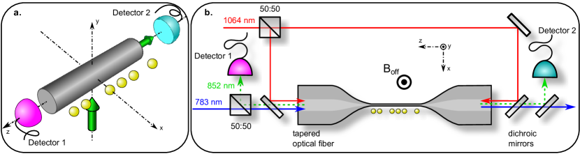
Here, we demonstrate that spin–orbit interaction of light leads to directional spontaneous emission of photons by atoms into a nanophotonic waveguide. We use a small number of cesium atoms as quantum emitters. The atoms are located in the vicinity of the surface of a subwavelength-diameter silica nanofiber. Thanks to this close proximity, the atoms are efficiently interfaced with the waveguide modes via their evanescent field part. Consequently, a fraction of the atomic fluorescence couples into the waveguide. A sketch of the experiment is shown in Fig. 1 a. As a key result of the present work, we find that more than 90 % of the optical power that is emitted into the fundamental mode of the nanofiber can be launched into a given direction. The asymmetry depends on both, the position of the atoms relative to the waveguide and on the polarization of the light emitted by the atoms, which we control by properly choosing the atom’s internal state and the polarization of the excitation laser light. The experiment is implemented using a nanofiber-based optical dipole trap for laser-cooled atoms Vetsch10 . The trapping potential consists of two diametric linear arrays of individual trapping sites along the nanofiber, located nm from the surface. Each site contains at most one atom and provides a strong sub-wavelength confinement Vetsch10 in every direction, considering the wavelength nm of the atomic transition used in the experiment. In contrast to previous experiments performed with this system, only one linear array of atoms is prepared ArXiv_Mitsch14 , see Methods. This allows us to locally probe the nanofiber-guided modes and to selectively place the atoms into regions of qualitatively different coupling. The optical nanofiber has a nominal radius of nm and is realized as the waist of a tapered optical fiber (TOF) Brambilla10 . It enables almost lossless coupling of light fields that are guided in a standard optical fiber into and out of the nanofiber section. The experimental setup, including the TOF, the laser beam paths, and the trapped atoms, is shown in Fig. 1 b.
The physical origin of the directional spontaneous emission of light into the nanofiber lies in the polarization properties of the guided modes. For an atom at the position , the scattering rate into one of the nanofiber modes is proportional to , where ∗ denotes the complex conjugation and is the atomic dipole operator. The coupling between the atomic emitters and a nanofiber mode thus crucially depends on the local unit polarization vector of the latter ArXiv_LeKien14 . For a sufficiently small fiber radius, as realized here, the optical nanofiber only guides the fundamental HE11 mode ArXiv_LeKien14 . These strongly guided optical fields are special in the sense that they show a significant coupling of the light’s spin and orbital angular momentum LeKien06b . The electric part of the local spin density is proportional to the ellipticity vector, which is given by the cross product . In strong contrast to paraxial light fields, the local spin density is position-dependent, in general not parallel to the guided field’s propagation direction, and even orthogonal to it in the case of quasi-linearly polarized guided fields Bliokh14 ; Bliokh12b ; Reitz14 . Most importantly for the following, in the latter case, the local spin changes sign when reversing the propagation direction of the guided field. This effect is a clear signature of the coupling of the light’s spin and orbital angular momentum. It allows us to control the direction of spontaneous emission that is coupled into the nanofiber.
In the following, we consider the quasi-linearly polarized HE11 modes ArXiv_LeKien14 . Four such modes, which have their main polarization oriented along the -axis or along the -axis ( or ) and which propagate in the forward or backward propagation direction ( or ), respectively, form a basis. The intensity of the quasi-linearly polarized basis modes is shown in Fig. 2 a. Figure 2 b shows a decomposition of the nanofiber-guided basis modes into the , , and polarization components ArXiv_LeKien14 . Here, we take the -axis as the quantization axis. With this choice, a - or -polarized light field exhibits a transverse spin. We plot the overlaps , , of the polarization vector with the orthonormal basis vectors . These overlaps are constant along the nanofiber axis and vary only slowly in the radial direction. However, they strongly vary as a function of the azimuthal position around the nanofiber. The circular polarization components of the guided modes, and thus the local spin density, depend on both, the position in the nanofiber transverse plane and the propagation direction of the mode. For the modes, at , i.e., on the left side of the nanofiber in Fig. 2, () is maximal, when the propagation direction of the mode is (), see upper left panel of Fig. 2 b. At a distance of nm from the nanofiber surface ( nm), (). Thus, these quasi-linearly polarized modes are locally almost perfectly circularly polarized, corresponding to a significant local spin density. Remarkably, this local spin points along the -axis, i.e., is orthogonal to the propagation direction of the mode, and changes sign when the propagation direction is reversed. At , i.e., on the right side of the nanofiber in Fig. 2, () is only 8%, when the propagation direction of the mode is (): The local spin density has opposite signs on opposite sides of the nanofiber. This effect is often referred as spin-Hall effect of light Onoda04 ; Hosten08 ; Bliokh08a . The overlap , however, does not show a dependence on the propagation direction and is identical on opposite sides of the nanofiber. For the modes, and, in particular, along the line . The modes contain no circular polarization ( and ) along . Thus, along this line, the polarization of the modes, and so the local spin density, is independent of their propagation directions.
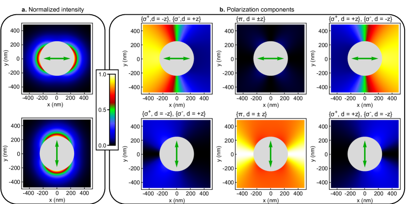
For our choice of quantization axis, our discussion revealed that the dependence of the local polarization on the propagation direction is strongest in the plane . In order to experimentally characterize the spontaneous emission of atoms into the optical nanofiber, we thus position the atoms either at or at . At these positions, the two modes are exactly -polarized and the modes are almost circularly polarized. The sign of the circularity is opposite for opposite propagation directions or on opposite sides of the nanofiber. As a consequence, a -polarized photon emitted by an atom couples exclusively and equally to the two counter-propagating modes, while a -polarized photon preferentially couples to one of the two modes.
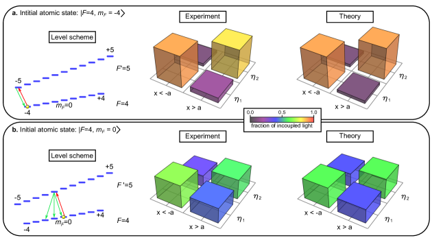
For the first set of measurements, we prepare the atoms in the outermost Zeeman substate . Here, is the total angular momentum quantum number and the magnetic quantum number. In order to avoid spin flips ArXiv_Mitsch14 and to spectrally separate neighboring optical transitions, a magnetic offset field of G is applied in the -direction, i.e., along the quantization axis. We drive the atomic cycling transition using an external -polarized laser field on the D2 line. At the position of the atoms, the polarization of the excitation laser is not modified by the nanofiber, see Supplemental Material. The involved atomic levels and transitions are shown in the left panel of Fig. 3 a. On this closed transition, the atoms only emit -polarized light. Two detectors, one at each end of the tapered optical fiber, are used to record the number of photons that are coupled into the nanofiber, see Fig. 1. The measurement interval is limited by the drop of the signal after about s which we attribute to the loss of atoms from the trap due to photon recoil heating. We sum up all recorded photon counts individually for each detector and correct for the optical losses of the setup. In the center panel of Fig. 3 a, we plot the fractions and of the total incoupled nanofiber-guided light that was detected by detector 1 and 2, respectively. When the atomic sample is located at , detector 1 (receiving light that propagates in the direction) records a significantly larger signal () than detector 2. The main propagation direction of the incoupled light is reversed when the atomic sample is prepared on the other side of the nanofiber, . In this case, detector 2 records the largest signal (). For this measurement configuration, a straightforward quantitative estimation of the expected fraction can be made and is shown in the right panel of Fig. 3 a: Only -polarized light is emitted and the coupling of the atoms to the locally -polarized modes is thus zero. Hence, is simply given by the position-dependent polarization overlap of the mode that propagates towards detector 1. This overlap is () when the atoms are located at (), which is in very good agreement with our experimental results.
We now prepare the atomic sample in the state. The external -polarized light field excites the atoms into the state, which can spontaneously decay via a , or transition, leading to the emission of a photon with the corresponding polarization. The involved atomic levels and transitions and the experimental results are shown in Fig. 3 b. Compared to the situation where we prepared the state, the emission into the nanofiber is now almost balanced. We find () for the atoms at (). These smaller values are theoretically expected: The probabilities for the emission of , and light for a decay from the state are , , and , respectively. As already discussed, the emitted -polarized light couples symmetrically into the waveguide. This light thus yields the same signal on the two detectors and reduces the contrast of any directed emission into the nanofiber. Moreover, as - and - polarized photons are emitted with similar probabilities, the emission rates into the counter-propagating modes of the nanofiber are almost equal. Our calculations then predict that of the total emission coupled into the nanofiber propagate into one direction ArXiv_LeKien14 . Here, we also take into account the fact that the intensities of the - and -polarized nanofiber modes are not equal at the position of the atoms Reitz14 , see Fig. 2 a. Our prediction is in good agreement with the experimental results.
In conclusion, we employed spin–orbit interaction of light to realize a directional nanophotonic atom–waveguide interface. We carried out our experiments with cesium atoms in the vicinity of a silica optical nanofiber. We demonstrated that the emission into the nanofiber in a given direction can be more than ten times stronger than in the opposite direction. By preparing the atoms in different internal Zeeman substates, we showed that the coupling ratios can be controlled via the polarization of the emitted light. Our work thus highlights how spin–orbit interaction of the nanofiber-guided light fundamentally influences the spontaneous emission process.
The presented effects are universal in the sense that they should also occur for other strongly-confined optical fields Noda07 ; Novotny12 , e.g., in integrated photonic waveguides Lund-Hansen08 . In the view of the rise of technologies such as silicon photonics Graydon10 , we therefore expect our findings to have an important impact on integrated optical signal processing. Our observations also pave the way towards an atom-mediated quantum photon router, in which the state of an atom controls the propagation direction of guided optical photons and which might thus constitute a central component for an optical quantum network Kimble08 .
In the course of completion our manuscript, we became aware of two related theoretical works ArXiv_Young14 ; ArXiv_Soellner14 . In both references a directional interface between a quantum dot and a photonic-crystal waveguide, that relies on spin–orbit interaction of light, is proposed.
Methods
Details on the nanofiber-based two-color trap and the prepared atomic sample
Laser-cooled cesium atoms are trapped in the evanescent field surrounding a silica optical nanofiber of nominal radius nm. The trapping potential is created by sending a blue-detuned running wave field with a free-space wavelength of nm and a power of mW and a red-detuned standing wave field at nm wavelength with a power of mW per beam into the nanofiber Vetsch10 . The blue- and the red-detuned fields are guided as quasi-linearly polarized fundamental HE11 modes. The main polarizations of the two fields are perpendicular to each other. Two diametric arrays of trapping sites are formed, and the calculated radial, azimuthal, and axial trap frequencies of each site are , , kHz, respectively. The trap minima are located at a distance of nm away from the nanofiber surface.
The atoms are loaded into the nanofiber-based trap from a magneto-optical trap via an optical molasses stage Vetsch10 . In this process, the collisional blockade effect limits the maximum number of atoms per trapping site to one and results in a maximum average filling factor of Vetsch10 . After loading, atoms are distributed over the two diametric arrays of trapping sites. For the study of the spontaneous emission into the nanofiber guided modes, the atoms in one of the two diametrically arranged arrays have to be removed. Otherwise, the symmetry of the system would prevent us from observing the directional emission into the nanofiber. In order to selectively remove atoms from one array of the nanofiber-based trap, we take advantage of a recently demonstrated technique for the preparation of atoms in one specific Zeeman state on one side of the nanofiber ArXiv_Mitsch14 . We end up with a few tens of atoms in a given state at either nm or nm, i.e., on the left or the right side of the fiber in Fig. 2.
Acknowledgements
Financial support by the Austrian Science Fund (FWF, SFB NextLite Project No. F 4908-N23 and DK CoQuS project No. W 1210-N16) and the European Commission (IP SIQS, No. 600645) is gratefully acknowledged. C.S. acknowledges support by the European Commission (Marie Curie IEF Grant 328545).
Author Contributions
R.M. and C.S. equally contributed to this work. R.M., C.S. and B.A. performed the experiment. R.M., C.S and P.S. analyzed the data. R.M., C.S., P.S. and A.R. wrote the manuscript. All authors discussed the results and reviewed the manuscript.
Additional information
The authors declare no competing financial interests. Correspondence and requests for materials should be addressed to P.S. or A.R. (email: schneeweiss@ati.ac.at, arno.rauschenbeutel@ati.ac.at).
References
- 1 Kao, C. K. Rev. Mod. Phys. 82, 2299–2303 Aug (2010).
- 2 Armani, D. K., Kippenberg, T. J., Spillane, S. M., and Vahala, K. J. Nature 421(6926), 925–928 February (2003).
- 3 Morrissey, M. J., Deasy, K., Frawley, M., Kumar, R., Prel, E., Russell, L., Truong, V. G., and Nic Chormaic, S. Sensors 13, 10449 (2013).
- 4 Zhao, Y., Edgar, J. S., Jeffries, G. D. M., McGloin, D., and Chiu, D. T. Phys. Rev. Lett. 99, 073901 Aug (2007).
- 5 Hosten, O. and Kwiat, P. Science 319, 787– February (2008).
- 6 Bliokh, K. Y., Aiello, A., and Alonso, M. A. The Angular Momentum of Light. Cambridge University Press, (2012).
- 7 Vetsch, E., Reitz, D., Sagué, G., Schmidt, R., Dawkins, S. T., and Rauschenbeutel, A. Phys. Rev. Lett. 104, 203603 (2010).
- 8 Rehler, N. E. and Eberly, J. H. Phys. Rev. A 3, 1735 (1971).
- 9 Scully, M. O., Fry, E. S., Ooi, C. H. R., and Wódkiewicz, K. Phys. Rev. Lett. 96, 010501 (2006).
- 10 Purcell, E. Phys. Rev. 69, 681 (1946).
- 11 Allen, L., Beijersbergen, M. W., Spreeuw, R. J. C., and Woerdman, J. P. Phys. Rev. A 45, 8185 (1992).
- 12 Noda, S., Fujita, M., and Asano, T. Nat Photon 1(8), 449–458 August (2007).
- 13 Novotny, L. and Hecht, B. Principles of Nano-Optics. Cambridge University Press, (2012).
- 14 Bliokh, K. Y., Bekshaev, A. Y., and Nori, F. Nat. Commun. 5 (2014).
- 15 Rodriguez-Fortuno, F. J., Marino, G., Ginzburg, P., O’Connor, D., Martínez, A., Wurtz, G. A., and Zayats, A. V. Science 340, 328 (2013).
- 16 Lin, J., Mueller, J. P. B., Wang, Q., Yuan, G., Antoniou, N., Yuan, X.-C., and Capasso, F. Science 340, 331 (2013).
- 17 Kapitanova, P. V., Ginzburg, P., Rodriguez-Fortuno, F. J., Filonov, D. S., Voroshilov, P. M., Belov, P. A., Poddubny, A. N., Kivshar, Y. S., Wurtz, G. A., and Zayats, A. V. Nat. Commun. 5 (2014).
- 18 Mitsch, R., Sayrin, C., Albrecht, B., Schneeweiss, P., and Rauschenbeutel, A. arXiv:1403.5129 (2014).
- 19 Brambilla, G. J. Opt. 12, 043001 (2010).
- 20 Fam Le Kien and Rauschenbeutel, A. arXiv:1406.0108 (2014).
- 21 Fam Le Kien, Balykin, V. I., and Hakuta, K. Phys. Rev. A 73, 053823 (2006).
- 22 Bliokh, K. Y. and Nori, F. Phys. Rev. A 85, 061801 Jun (2012).
- 23 Reitz, D., Sayrin, C., Albrecht, B., Mazets, I., Mitsch, R., Schneeweiss, P., and Rauschenbeutel, A. Phys. Rev. A 89, 031804 (2014).
- 24 Onoda, M., Murakami, S., and Nagaosa, N. Phys. Rev. Lett. 93, 083901 Aug (2004).
- 25 Bliokh, K. Y., Niv, A., Kleiner, V., and Hasman, E. Nat Photon 2(12), 748–753 December (2008).
- 26 Lund-Hansen, T., Stobbe, S., Julsgaard, B., Thyrrestrup, H., Sünner, T., Kamp, M., Forchel, A., and Lodahl, P. Phys. Rev. Lett. 101, 113903 Sep (2008).
- 27 Graydon, O. et al. Nat. Phot. 4, 491 (2010).
- 28 Kimble, H. J. Nature 453, 1023 (2008).
- 29 Young, A. B., Thijssen, A., Beggs, D. M., Kuipers, L., Rarity, J. G., and Oulton, R. arXiv:1406.0714 June (2014).
- 30 Söllner, I., Mahmoodian, S., Javadi, A., and Lodahl, P. arXiv:1406.4295 June (2014).