Optimized generation of spatial qudits by using a pure phase spatial light modulator
Abstract
We present a method for preparing arbitrary pure states of spatial qudits, namely, -dimensional () quantum systems carrying information in the transverse momentum and position of single photons. For this purpose, a set of slits with complex transmission are displayed on a spatial light modulator (SLM). In a recent work we have shown a method that requires a single phase-only SLM to control independently the complex coefficients which define the quantum state of dimension . The amplitude information was codified by introducing phase gratings inside each slit and the phase value of the complex transmission was added to the phase gratings. After a spatial filtering process we obtained in the image plane the desired qudit state. Although this method has proven to be a good alternative to compact the previously reported architectures, it presents some features that could be improved. In this paper we present an alternative scheme to codify the required phase values that minimizes the effects of temporal phase fluctuations associated to the SLM where the codification is carried on. In this scheme the amplitudes are set by appropriate phase gratings addressed at the SLM while the relative phases are obtained by a lateral displacement of these phase gratings. We show that this method improves the quality of the prepared state and provides very high fidelities of preparation for any state. An additional advantage of this scheme is that a complete modulation is obtained by shifting the grating by one period, and hence the encoding is not limited by the phase modulation range achieved by the SLM. Numerical simulations, that take into account the phase fluctuations, show high fidelities for thousands of qubit states covering the whole Bloch sphere surface. Similar analysis are performed for qudits with and .
1Departamento de Física, FCEyN, Universidad de Buenos Aires, Buenos Aires 1428, Argentina
2Departamento de Física, IFLP, Universidad Nacional de La Plata, C.C. 67, 1900 La Plata, Argentina
3 Center for Optics and Photonics, Universidad de Concepción, Casilla 4016, Concepción, Chile
4 Departamento de Física, MSI-Nucleus on Advanced Optics, Universidad de Concepción, Concepción, Chile
5 Departamento de Física, Universidade Federal de Minas Gerais, Caixa Postal 702, Belo Horizonte, MG 30123-970, Brazil
* rebon@fisica.unlp.edu.ar
(270.5585) Quantum information and processing; (230.6120) Spatial light modulators; (050.1950) Diffraction gratings.
References
- [1] S. M. Barnett, “Quantum Information” (Oxford University Press, Oxford, 2009).
- [2] P. Kok and B. W. Lovett, “Introduction to Optical Quantum Information Processing” (Cambridge University Press, Cambridge, 2010).
- [3] L. Neves, G. Lima, J. G. Aguirre-Gómez, C. H. Monken, C. Saavedra, and S. Pádua, “Generation of Entangled States of Qudits using Twin Photons,” \prl 94, 100501 (2005).
- [4] M. N. O’Sullivan-Hale, I. Ali-Khan, R. W. Boyd, and J. C. Howell, “Pixel Entanglement: Experimental Realization of Optically Entangled and Qudits,” \prl 94, 220501 (2005).
- [5] L. Neves, S. Pádua, and C. Saavedra, “Controlled generation of maximally entangled qudits using twin photons,” \pra 69, 042305 (2004).
- [6] M. A. Solís-Prosser and L. Neves, “Remote state preparation of spatial qubits,” \pra 84, 012330 (2011).
- [7] P. Kolenderski, U. Sinha, L. Youning, T. Zhao, M. Volpini, A. Cabello, R. Laflamme, and T. Jennewein, “Aharon-Vaidman quantum game with a Young-type photonic qutrit,” \pra 86, 012321 (2012).
- [8] B. Marques, M. R. Barros, W. M. Pimenta, M. A. D. Carvalho, J. Ferraz, R. C. Drumond, M. Terra Cunha, and S. Pádua, “Double-slit implementation of the minimal Deutsch algorithm,” \pra 86, 032306 (2012).
- [9] S. Etcheverry, G. Cañas, E. S. Gómez, W. A. T. Nogueira, C. Saavedra, G. B. Xavier, and G. Lima, “Quantum key distribution session with 16-dimensional photonic states,” Sci. Rep. 3, 2316 (2013).
- [10] G. Lima, A. Vargas, L. Neves, R. Guzmán, and C. Saavedra, “Manipulating spatial qudit states with programmable optical devices,” Opt. Express 17, 10688 (2009).
- [11] G. Lima, L. Neves, R. Guzmán, E. S. Gómez, W. A. T. Nogueira, A. Delgado, A. Vargas, and C. Saavedra, “Experimental quantum tomography of photonic qudits via mutually unbiased basis,” Opt. Express 19, 3542 (2011).
- [12] M. A. Solís-Prosser, A. Arias, J. J. M. Varga, L. Rebón, S. Ledesma, C. Iemmi, and L. Neves, “Preparing arbitrary pure states of spatial qudits with a single phase-only spatial light modulator,” Opt. Lett. 38, 4762 (2013).
- [13] M. A. Solís-Prosser and L. Neves, “Measurement strategy for spatially encoded photonic qubits,” \pra 82, 055801 (2010).
- [14] R. Cohn and M. Liang, “Approximating fully complex spatial modulation with pseudorandom phase-only modulation,” Appl. Opt. 33, 4406 (1994).
- [15] P. Birch, R. Young, D. Budgett, and C. Chatwin, “Dynamic complex wave-front modulation with an analog spatial light modulator,” Opt. Lett. 26, 920 (2001).
- [16] E. G. van Putten, I. M. Vellekoop, and A. P. Mosk, “Spatial amplitude and phase modulation using commercial twisted nematic LCDs,” Appl. Opt. 47, 2076 (2008).
- [17] J. A. Davis, D. M. Cottrell, J. Campos, M. J. Yzuel, and I. Moreno, “Encoding Amplitude Information onto Phase-Only Filters,” Appl. Opt. 38, 5004 (1999).
- [18] V. Bagnoud and J. D. Zuegel, “Independent phase and amplitude control of a laser beam by use of a single-phase-only spatial light modulator,” \ol 29, 295 (2004).
- [19] A. Lizana, I. Moreno, A. Márquez, C. Iemmi, E. Fernández, J. Campos, and M. J. Yzuel, “Time fluctuations of the phase modulation in a liquid crystal on silicon display: characterization and effects in diffractive optics,” Opt. Express 16, 16711 (2008).
- [20] A. Lizana, A. Marquez, L. Lobato, Y. Rodange, I. Moreno, C. Iemmi, and J. Campos, “The minimum Euclidean distance principle applied to improve the modulation diffraction efficiency in digitally controlled spatial light modulators,” Opt. Express 18, 10581 (2010).
- [21] D. C. Burnham and D. L. Weinberg, “Observation of simultaneity in parametric production of optical photon pairs,” \prl 25, 84 (1970).
- [22] P. G. Kwiat, K. Mattle, H. Weinfurter and A. Zeilinger, “New High-Intensity Source of Polarization-Entangled Photon Pairs,” \prl 75, 4337 (1995).
- [23] P. G. Kwiat, E. Waks, A. G. White, I. Appelbaum, and P. H. Eberhard, “Ultrabright source of polarization-entangled photons,” \pra 60, R773 (1999).
- [24] Y. Xue, A. Yoshizawa, and H. Tsuchida, “Hong−Ou−Mandel dip measurements of polarization-entangled photon pairs at 1550 nm,” Opt. Express 18, 8182 (2010).
- [25] J. W. Goodman, “Introduction to Fourier Optics” (Roberts & Company, Colorado, 2005).
- [26] I. D. Ivanovic, “Geometrical description of quantal state determination,” J. Phys. A 14, 3241 (1981).
- [27] W. K. Wootters and B. D. Fields, “Optimal state-determination by mutually unbiased measurements,” Ann. Phys. 191, 363 (1989).
- [28] J. Fiurášek, “Maximum-likelihood estimation of quantum measurement,” \pra 64, 024102 (2001).
- [29] F. Martínez, A. Márquez, S. Gallego, J. Francés and I. Pascual, “Extended linear polarimeter to measure retardance and flicker: application to liquid crystal on silicon devices in two working geometries” Opt. Eng. 53, 014105 (2014).
- [30] A. Hermerschmidt, S. Osten, S. Krüger, and T. Blümel, “Wave front generation using a phase-only modulating liquid-crystalbased micro-display with HDTV resolution,” Proc. SPIE 6584, 65840E (2007).
1 Introduction
One of the main challenges in the field of quantum information science is the ability to generate, modify and measure the quantum systems which are the information carriers in quantum information processing and computing protocols [1]. In this context, photons are the natural choice for communications since they are easily transportable, slowly affected by decoherence and have several degrees of freedom to encode information [2]. A typical encoding are the so-called spatial qudits, namely, -dimensional () quantum systems carrying information in the discretized transverse momentum and position of single photons [3, 4]. In the simplest approach, this discretization is achieved when the photons are made to pass through an aperture with slits which sets the qudit dimension [5]. Due to this simplicity, spatial qudits enables one to work in high dimensions without cumbersome optical setups and for that reason they have drawn interest for miscellaneous applications such as quantum information protocols [6], quantum games [7], quantum algorithms [8], and quantum key distribution [9]. Most of those applications has benefited from the recent developments on the control of spatial qudits based on the technology of electrically addressed spatial light modulators (SLMs). SLMs have dramatically simplified and broadened the range of operations that can be implemented in real time on spatial qudits for state preparation, transformation and measurement [10, 11, 12, 13].
Initially, Lima et al. [11] have shown that by imaging the output beam of an amplitude-only SLM onto a phase-only SLM allows one to get complete and independent control of the amplitude and phase of the complex coefficients that define the qudit state. Therefore, this scheme requires two SLMs at each link of the setup (preparation, transformations, and measurements) in order to implement arbitrary operations at each one. Besides being costly in terms of optical resources, it entails two drawbacks: (i) the overall diffraction efficiency at each link is very low, and (ii) in order to avoid even more losses, the image of the first SLM must match the second one pixel by pixel, which is difficult in practice. In a recent Letter [12], we presented a proof-of-principle demonstration of a method which proposed the use of a single phase-only SLM to control independently the amplitude and phase of the state coefficients. This method is, thereby, less costly, offer a much higher diffraction efficiency (we estimated a 10 times higher efficiency), which is relevant when working with single photon sources, and does not require an optical system for projecting the image of a SLM onto a second one in order to obtain the complex modulation. Among the different techniques to represent a complex function in a single SLM [14, 15, 16] our method follows the proposals of [17, 18] for encoding amplitude and phase information onto a phase-only SLM. To this end, phase diffraction gratings were displayed in those zones corresponding to the slits. The desired amplitude of the complex coefficients, was obtained by controlling the amount of light diffracted on the first order which is a function of the phase modulation depth of the grating. The phase of the complex coefficients, which defines the required relative phase, was achieved by adding a constant phase value to the grating. The required complex light distribution was obtained after filtering the first diffracted order in the Fourier plane. We shall refer to this method as the phase-addition (PA) method.
Although the PA method gives, on average, good fidelities of preparation for spatial qubits and qudits of dimension at least up to 7, we observed that many of the prepared states had their fidelities reduced under the same experimental conditions for state preparation and characterization. In that paper [12], we pointed out that this effect was possibly due to temporal phase fluctuations of the used SLM which was based on liquid crystal on silicon (LCoS) technology. In fact, LCoS may lead to flicker in the optical beam because of the digital addressing scheme (pulse width modulation) which introduces, among other undesirable effects, those phase fluctuations [19, 20] that affect the quality of the encoded state. This spurious effect will be amplified as the number of SLMs in a given setup increases, so it is desirable to eliminate or at least minimize it.
In this paper we first analyze, by numerical simulation, the effects of the phase fluctuations on the quality of the states prepared by the PA method and compare the results with the experimental ones shown in the previous work. Our results corroborate the conjecture that those fluctuations are the main responsible for the reduction of the fidelities. After that, we propose an alternative scheme of encoding spatial qudits that minimizes those effects and, consequently, improve the quality of the preparation. In this scheme the amplitudes of the slits also are controlled by means of blazed gratings, but the values of the phases of the state coefficients are obtained by performing lateral displacements of the gratings instead of by adding a constant phase. In this way the required phase is controlled only by the grating position, which is not affected by phase fluctuations. We shall refer to this method as the grating-displacement (GD) method. Besides improving the preparation, the new encoding scheme is more flexible than the previous one regarding the phase modulation range achieved by the SLM. The PA method requires a SLM with a phase modulation of at least , while the GD method is not limited by this condition since a complete modulation is obtained by shifting the grating by one period. This fact is important specially when long wavelengths (usually near IR), as those obtained by parametric down-conversion [21, 22, 23, 24], are used. The performance of the GD method is analyzed by simulating the preparation of arbitrary states and their tomographic reconstruction. We report the results obtained for thousands of qubit states covering the whole Bloch sphere surface and spatial qudits of dimension and . By studying the fidelities of preparation we show that the GD method overcomes the PA one.
2 The grating-displacement method
The encoding process for the generation of pure states of spatial qudits can be explained as follows. When a paraxial and monochromatic single-photon field is transmitted through an aperture described by a complex transmission function , its state, assumed here to be pure, is transformed as
| (1) |
where is the transverse position coordinate and is the normalized transverse probability amplitude for this state, i.e., . Now, let us consider that is an array of rectangular slits of width , period and length , where each slit, , has a transmission amplitude . Thus, will be given by
| (2) |
where . Without loss of generality and for simplicity, we will assume that is constant across the region of the slits. Hence, the state of the transmitted photon in Eq. (1) will be [3]
| (3) |
where and denotes the state of the photon passing through the slit .
As we have shown in [12], in order to prepare arbitrary states of the form of Eq. (3) with a single phase-only SLM, a phase one-dimensional diffraction grating is displayed on the different regions of the SLM, each of them corresponding to a particular slit. In this work a blazed phase profile is selected to achieve the maximum diffraction efficiency in the first order, which can be expressed as [25]
| (4) |
where is the phase modulation depth and . When the first order efficiency has a maximum value of 100%. By selecting other value for , it is possible to modulate the amount of light diffracted on the order and consequently the amplitude of each slit. Equation (4) corresponds to an ideal blazed profile with continuous modulation. Nevertheless, given that the representation of the grating period is carried out through a finite number of pixels, this imposes a discretization in the phase levels used to generate the blazed profile. Thus if is the number of quantization levels, the maximum efficiency value will be assigned to the maximum amplitude of the slit coefficients, i.e., corresponds to . Other amplitude values will correspond to other values of which are obtained from Eq. (4). If the employed SLM do not reach 2 phase modulation then the relative slit amplitudes should be recalculated with respect to the maximum efficiency achieved. In order to avoid the introduction of additional phases in the encoding process, the phase gratings should be designed with zero mean value. However, as the SLM can only display positive phase values, the gratings are generated with a mean value equal to half of the maximum phase modulation depth which is for a blazed grating.
Let us now describe the GD method to control the phase of the complex coefficients, , in Eq. (3). It can be understood by analyzing the transfer function of the grating. If it is assumed that when the grating is centered at its phase value is zero, the transfer function of the slit in the far field can be written as:
| (5) |
where is the amplitude of the -th diffraction order, is the position along the grating and is the grating period, both measured in pixel units. A lateral displacement of the grating by a distance of pixels from , introduces a phase shift
| (6) |
in the -th order, since the transfer function now is given by
| (7) |
By selecting the first diffraction order to obtain the required complex modulation, the transfer function of the grating will be
| (8) |
and the phase shift introduced by the translation is . When the maximum amplitude is normalized, regardless what happens in the other diffraction orders, its value coincides with in Eq. (4).
We will show in the next sections that as the phase of the complex coefficients is determined by the grating position, its value is almost unaffected by phase fluctuations.
3 Numerical simulations for state preparation
3.1 Proposed experimental setup
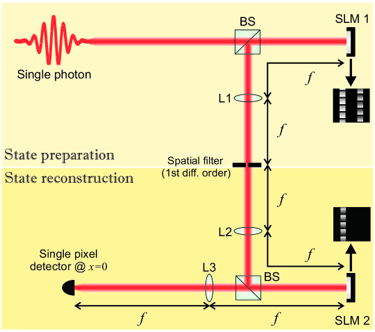
In order to analyze the performance of both PA and GD encoding methods against the variation of different parameters of the SLM (phase fluctuation levels, number of pixels used to represent a grating period, etc.) we carried out numerical simulations of a realistic optical setup designed to prepare and characterize spatial qudit states. The proposed experimental setup is depicted in Fig. 1. A given source generates a single-photon field in the pure state given by the left part of Eq. (1). As mentioned earlier, we assume that the transverse probability amplitude is constant across the region where the slits are displayed in the SLM. In the upper part of the setup, used for state preparation, a phase-only SLM (SLM1) is addressed with a phase mask—either by PA or GD method—corresponding to the spatial qudit state intended to be prepared. SLM1 is placed in the front focal plane of lens L1 and an iris diaphragm is placed at its back focal plane in order to filter the first diffracted order which carries the required information [12]. In the lower part of the setup, used to reconstruct the quantum states by tomography, the Fourier transform of the first diffracted order is projected onto a second SLM (SLM2), placed at the back focal plane of L2. SLM2 is used to encode the measurement bases employed to perform the tomographic process as described in [11]. A single pixel detector is placed at the Fourier transform plane of SLM2, in the center of its first diffraction order (). This detector registers the single count rates that after normalization give us the probabilities to reconstruct the states. It is important to note that with this configuration it is possible to perform arbitrary projections of the input state without the need to carry on measurements in the near field. In this way, the optical setup remains unchanged. In particular, we perform projections onto the informational complete set of mutually unbiased basis [26, 27] following the experiment reported in [11]. Finally, we apply maximum likelihood technique to obtain the best state estimation consistent with the requirements of a physical state [28].
3.2 Model for temporal phase fluctuations
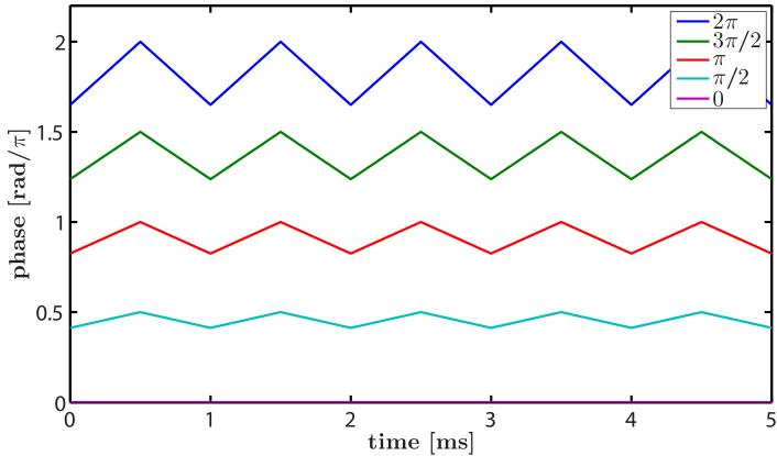
As it was mentioned, reflective SLMs such as LCoSs, are usually employed to obtain pure phase modulation. In a previous paper [19, 29], a simple model has been proposed to describe the phase fluctuations that are associated with these devices. Although the exact shape of the perturbation varies from one SLM to another one, and depends on the pulse width modulation sequence used to address the electrical signal and the selected gray level, a suitable approximation which describes the general behavior is a triangular phase fluctuation whose height increases linearly with the phase value. Also, it should be considered that in many devices the digital addressing sequence can be programmed. Shorter sequences offer the possibility of higher repetition rate in a frame period which leads to a reduction in the flicker amplitude; nevertheless, the number of addressable phase levels is lower in these cases [30]. According to the selected sequence the phase fluctuations can reach values as high as 120% of the average phase value [20]. Therefore, to illustrate their effects on each method (PA and GD) we chose different amplitudes of fluctuation, corresponding to intermediate sequences, to perform the numerical simulations. We have considered phase fluctuations ranging from to of the average phase value. As an example, a model for typical temporal fluctuation is shown in Fig. 2 where the amplitudes fluctuation are of the average phase value.
It was noted, through the numerical simulations, that the influence of the synchronization between the temporal signals sent to both modulators (SLMs 1 and 2 in Fig. 1), on the final result is irrelevant. As a consequence we have decided to consider the second SLM, employed to perform the tomographic projections, as a device without fluctuations and transfer the phase fluctuations of both elements to the first SLM, used to prepare the state.
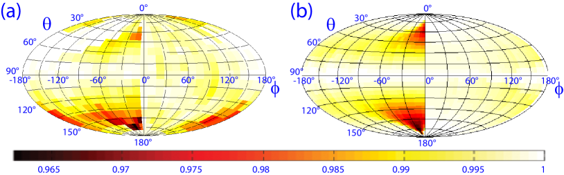
In order to validate the mentioned assumptions and the proposed model, we compared the experimental results obtained in [12] with the corresponding numerical simulation. To this end we used the same setup and encoding scheme (PA method) of the previous work considering the case of a blazed grating. Here and in the following section, we quantify the quality of the preparation process with the fidelity, , between the state intended to be prepared, , and the density matrix of the state actually prepared and reconstructed by tomography, . Ideally, it is desirable to have . The Bloch spheres showing the fidelities of preparation of spatial qubits are shown in Fig. 3. Figure 3(a) corresponds to the experimental results of [12], and Fig. 3(b) corresponds to the results obtained by numerical simulation. Although the experimental results show a region of low fidelities around which are not reproduced by the simulation, it is apparent the similarity between them in all other regions of the Bloch’s sphere. This slighty difference between both results arises from the fact that the model used to simulate the temporal fluctuations is just a first order aproximation. Besides, the aim of this study is to compare the perfomance of both encoding methods under phase fluctuations and not to exactly reproduce its shape.
4 Results
As mentioned above, it is expected that the proposed encoding method (GD) be barely affected by phase fluctuations, since the phase of the complex coefficients are determined by the grating positions, which are not influenced by those fluctuations. Nevertheless, a possible drawback is that, in principle, there are fewer available phase levels than in the PA method. In the latter the available phase values are determined by the digital sequence used to address the LCoS whereas in the GD method the phase values are quantized by the number of pixels used to represent a grating period, i.e., the minimum phase shift is . We will show here that for a sufficiently large value of , this drawback has smaller effects than the phase fluctuations in the PA method.
Considering spatial qubits, let us see how the choice of the grating period, , affects the quality of the preparation. For blazed gratings with , , and pixels we simulated the preparation of 2112 states uniformly distributed over the Bloch sphere surface. The results are shown in Figs. 4(a)-4(c), respectively. For each , it is noticeable a fidelity decrease with a periodic distribution that depends on how far or close is the phase of the quantum state from the phase value that we are able to represent. This decrease is due to the phase quantization rather than the phase fluctuations introduced by the LCoS and, as expected, it becomes smaller as increases. Figure 4(a) shows the fidelities obtained with a 4-pixel grating period. In Fig. 4(b), with a -pixel grating period the results are much better and for in Fig. 4(c) the obtained fidelities are excellent. In a realistic scenario, a grating with -pixels period provides high diffraction efficiency and enables the first diffraction order to be placed far away from the zeroth order on the Fourier plane. In this way it can be easily filtered and the light distribution is not corrupted by unwanted noise. Gratings with larger period will improve the phase resolution but the first and zeroth order will be so close that would make it difficult to perform the filtering. Hence, to compare the performance of both methods (PA and GD) under fluctuations on the SLMs we have chosen a grating with 16-pixels period.
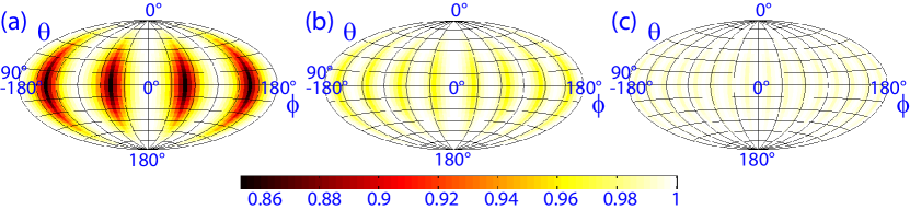
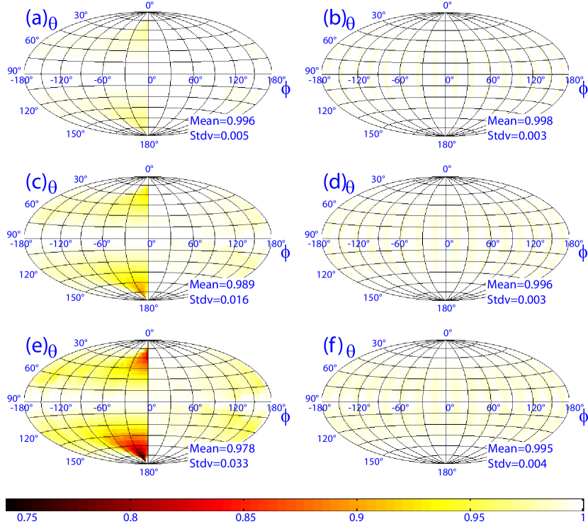
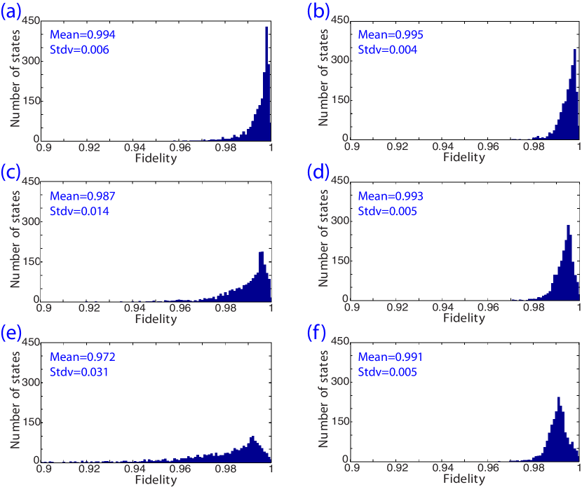
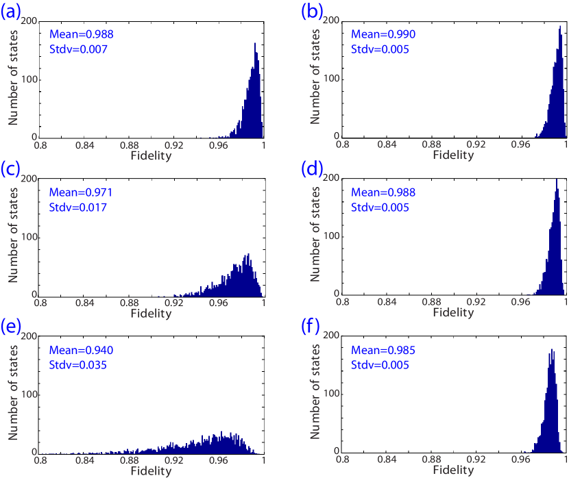
Figure 5 shows, for both methods (PA first column and GD second column), the fidelities of preparation for qubit states considering three different phase fluctuation amplitudes: [Figs. 5(a) and 5(b)], [Figs. 5(c) and 5(d)] and [Figs. 5(e) and 5(f)] of the average phase value. From these Bloch spheres it is clear that while the PA method is strongly dependent on the phase fluctuation amplitude, the GD method remains almost unaffected. Two thousand arbitrary pure states, corresponding to spatial qudits of higher dimension, have been prepared. The histograms shown in Fig. 6 represent the number of states of dimension whose fidelity values belong to a particular interval. Figures 6(a) and 6(b) correspond, respectively, to the results obtained with the PA and GD encoding method for phase fluctuations of 20% of the average phase value. Figures 6(c) and 6(d) show the equivalent results for phase fluctuations of 30% and Fig. 6(e) and 6(f) the same for fluctuations of 60%. The results for qudits of dimension are shown in Fig. 7. Again the left column represents the histograms obtained from the PA method and the right column to those obtained from the GD method. Figures 7(a) and 7(b) correspond to phase fluctuations of 20%, Figs. 7(c) and 7(d) to fluctuations of 30% and Figs. 7(e) and 7(f) to phase fluctuations of 60%. In a similar way that in the case of a Hilbert space of dimension , the results obtained for dimensions and shown that the GD method leads to an increase of the mean fidelity and to a diminution of the standard deviation which agrees with the fact that the encoding applied in the preparation and reconstruction processes is almost not affected by phase noise.
5 Conclusions
In this work we have proposed a new method to encode spatial qudit states using a LCoS as a single phase-only spatial light modulator. In this method the complex transmissions of the slits that are used to represent the quantum state are encoded by means of phase diffraction gratings. The amplitudes are driven through the phase modulation depth of the grating and the required phases are controlled by performing lateral translations of the grating. Given that the phase values are determined by the grating position the method is almost unaffected by the phase fluctuations associated to LCoSs.
We have analyzed the performance of the proposed method by numerical simulations where we evaluated the preparation of arbitrary states in a first SLM and its tomographic reconstruction using projective measurements onto a pre-fixed basis addressed in a second SLM. The proposed method (GD) has been compared with a previous one in [12] where the required phases were controlled by adding a constant phase value to the grating (PA). This has been done under different phase fluctuation intensities for qubits, and qudits of dimension and . In all cases the results of the simulations have shown a greater robustness of the GD method against phase fluctuations when comparing with the PA method. In addition the GD method offers wider experimental flexibility allowing one to use SLMs with a maximum phase modulations below . This feature is important specially when long wavelengths (usually near IR), as those of photons obtained by parametric down-conversion, are used.
Therefore, the method proposed here may become a valuable tool for experiments based on spatial qudits, specially when one has to assemble two or more SLMs (e.g., for state preparation and transformations) subjected to phase fluctuations. By using the GD method one minimizes the noise effects caused by the fluctuations and, consequently, improve the realization of the protocol of interest.
Acknowledgments
This work was supported by UBACyT 20020100100689, CONICET PIP 112-200801-03047 and ANPCYT PICT 2010-02179 (Argentina), CNPq 485401/2013-4 and FAPEMIG APQ-00149-13 (Brazil), and CONICYT PFB08-24 and Milenio ICM P10-030-F (Chile). M.A.S.P. acknowledges financial support from CONICYT (Chile).