Imprinting skyrmions in thin films by ferromagnetic and superconducting templates
Abstract
Magnetic skyrmions are promising candidates as information carriers in a new generation of memories. How to generate and stabilize skyrmions is essential for their successful application to technology. Here we theoretically demonstrate that arrays of skyrmions can be imprinted in ultrathin ferromagnetic films in large numbers by bringing a magnetic nanostructured template close to the film. Two kind of templates, allowed by present-day nanotechnologies, are studied: arrays of ferromagnetic nanorods and superconducting vortices. Skyrmions are generated when exposing magnetic films to the template fields for short times and remain stable after removing the template.
Skyrmion lattices of nanometer range have been observed in magnetic thin films induced by interfacial Dzyaloshinskii-Moriya (DM) interactions Ferriani ; Heide , following the lattices initially observed in bulk non-centrosymmetric crystals Muhlbauer ; Yu . Some important parameters can be adjusted experimentally in thin films, such as the perpendicular magnetic anisotropy chappert or the DM strength Sampaio . This makes magnetic films, such as Co layers on Pt, excellent systems for studying and optimizing skyrmions Sampaio .
The potential use of magnetic skyrmions as information carriers fert_comment ; felser ; nagaosa would require the controlled nucleation of a large number of them. Recently, skyrmions have been experimentally generated by processes such local injection of currents Sampaio . In this work we theoretically demonstrate an alternative way to create stable tunable arrays of large numbers of skyrmions in a thin film surface: imprinting them with nanostructured magnetic templates. We show how arrays of magnetic dipoles or monopoles, separated a distance of some tenths of nanometers, can be used as nanomagnetic templates. We discuss below how present nanotechnologies involving either ferromagnetic rods or superconducting vortices can be tailored to fabricate these nanotemplates.
Non-trivial magnetic structures such as skyrmions appear in ferromagnetic films typically because of the competition between the exchange and the DM interactions felser . To simulate these systems, we have developed an own-coded micromagnetic procedure APL , extended here to include the additional DM term Rohart . The Landau-Lifshitz-Gilbert equation is solved by a 4th order Runge-Kutta method. We consider in-plane periodic boundary conditions to avoid edge effects Ohe ; all calculations have been checked to represent an extended film, independently of the calculation window. We assume ultra thin samples and typical realistic parameters corresponding to perpendicular magnetized Co layer on Pt Sampaio (see Methods for details). Magnetostatic energy is disregarded; we have numerically confirmed that it is negligible in these thin systems (as in Sampaio ).
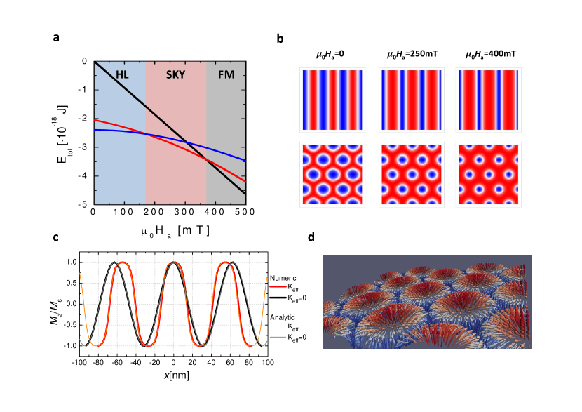
We first calculate a magnetic phase diagram for the studied films, assuming no anisotropy for simplicity (fig. 1a). The total energy, consisting of the DM, exchange, and Zeeman terms, is plotted for different initial magnetic configurations as a function of the applied magnetic field . Similar to other studies Muhlbauer ; Yu ; nagaosa , we find that at zero applied field the minimum energy corresponds to a phase of stripes of undulating out-of-plane component of the magnetization, commonly referred to as the helical phase nagaosa . We have analytically derived that the minimum of energy for an infinitely long (in the direction) film with no applied field follows a harmonic magnetization profile with period , around 63nm in our studied case (see Supplementary Material Section II, also for the case of a non-zero anisotropy constant or a given ). These solutions are compared in fig. 1c with our numerical simulations for a longitudinal section of our 2D film in the helical phase. Numerical and analytical results perfectly match, confirming our numerical techniques.
An hexagonal lattice of skyrmions appear as a metastable solution at low applied fields ; this phase becomes the ground state at mT. The obtained skyrmions are hedgehog type (fig. 1d) and their size decreases with increasing , as in Sampaio . When increases to about 370mT, the ferromagnetic state becomes the lowest energy state.
Our calculations show that it is not easy to generate skyrmions starting from configurations such a ferromagnetic state (as previously seen milde ; nagaosa ), even at the conditions such that a skyrmion lattice has the minimum energy (e. g. applied field of few hundred mT in our case). The reason for that is that generating skyrmions requires overcoming a topological barrier nagaosa . It therefore becomes essential to design a procedure to generate skyrmions in these magnetic films under general conditions, even at zero applied field. We propose here a robust method for imprinting skyrmions by bringing a magnetic template -with a field profile that can locally induce the required topological change- close to the film. The initial purely ferromagnetic state will be converted into a skyrmion phase by using magnetic templates with the adequate protocol and conditions.
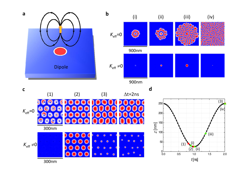
We have seen above that the combination of DM and exchange energies results in a relevant length scale at which non-trivial structures would tend to be formed, so we would like our magnetic template fields to vary at this scale. We start with dipolar sources (fig. 2a). It has been shown ross ; pacheco ; nikulina ; deteresa that magnetic nanowires can produce a dipolar stray magnetic field in their vicinity, particularly if they have a small aspect ratio. These nanowires can form arrays with separation of tenths of nanometers, at the scale of interest. Magnetic tips were previously proposed to generate skyrmions and bubbles in RKKY systems kirakosyana . Also, magnetic vortices have been proposed for creating skyrmions sun , although in that case the interfacial exchange energy, and not stray field was the mechanism for skyrmion generation.
We show in Fig. 2b the effect of approaching a single magnetic dipole of magnetic moment Li to the film up to a distance of 25nm. If there is no anisotropy (=0), the dipole induces a ring of opposite magnetization (red), overcoming the topological barrier. The width of this ring is on the order of . When the dipole is removed, a structure consisting of filaments of typical size develops and eventually propagates throughout all the film (similar structures were experimentally seen in milde ). Interestingly, if the film has (fig. 2b) then the picture changes. A kind of magnetic bubble is formed at the dipole spot but now anisotropy prevents propagation of the filaments. Instead, the bubble shrinks into a stable magnetic skyrmion of smaller size. Interesting features appear when considering arrays of magnetic dipoles as templates. In fig. 2c we show that stable arrays of large bubbles (when ) or smaller skyrmions (when ) are created and remain even after removing the template. These arrays are stabilized owing to the interaction between neighbouring bubbles, via DM and exchange interactions, since magnetostatic energy is negligible. Varying the lattice constant of the dipole arrays results in a rich behavior (Supplementary Material section III). An important consequence of these simulations is that stable skyrmions appear in ultrathin magnetic films with magnetic anisotropy without the need of applying an external overall magnetic field. This happens, both in the the case of a single skyrmion induced by a single magnetic dipole (fog. 2b) and a disordered array of them induced after approaching an ordered array of magnetic dipoles (fig. 2c).
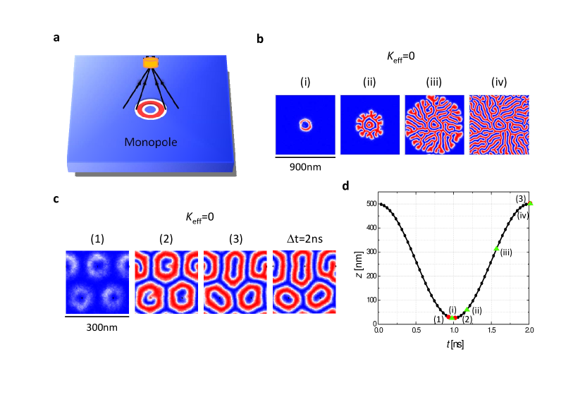
Another interesting possibility to explore is using monopolar field sources (fig. 3a). These can be created either by using arrays of long nanowires ross ; pacheco ; nikulina ; deteresa or, alternatively, by arrays of superconducting vortices in films carneiro ; SVL . The latter can be tailored with separations of few tenths of nanometers by having an array of antidots in superconducting films (mosh and references therein). At distance of the order of the Pearl penetration depth (typically, tenths on nanometers pearl ; SVL ), the vortices in thin superconductors create to a good approximation a monopolar field with magnetic charge carneiro ; SVL , where is the flux quantum. We show in fig. 3b the magnetization distribution of a film with in-plane periodic boundary conditions when a monopolar field is approached to a distance of 25nm and then is moved away. Similar structures as those for single dipoles (fig. 2b) are found. An array of monopoles create magnetic structures following the monopoles array periodicity, as for dipoles, but the structures have a ring shape of alternating magnetization instead of a bubble structure. Interestingly, we observe that no magnetic structures can be generated by monopolar fields when , both for single sources and arrays (although they can be imprinted if the monopoles are closer to the film). The reason for that is that the stray field created by vortex monopoles at 25nm is less than that required to overcome the anisotropy effective field (see Supplementary Material section I), on the order of 2T (whereas dipolar sources at 25nm do provide such field values).
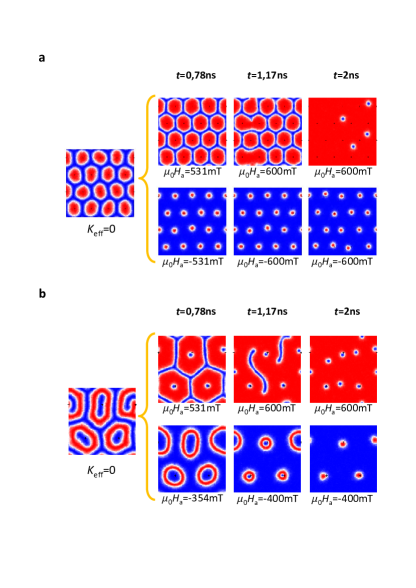
Thus, arrays of dipolar sources generate bubble-like magnetic structures that transform, after some elapsed time, into an array of skyrmions if the film has some perpendicular anisotropy (fig. 2c), even in the absence of an overall applied magnetic field. For monopolar sources, magnetic structures also appear for films with low anisotropy, whereas the topological barrier cannot be overcome in some cases when there is anisotropy. We now demonstrate that, for all cases including films without anisotropy, the arrays of imprinted magnetic structures can be turned into arrays of skyrmions simply by applying a uniform perpendicular magnetic field . On fig. 4a we show how applying results in the presence of skyrmions or anti-skyrmions. When the applied field is positive only a few anti-skyrmions are found in a background of positive magnetization, whereas an array of skyrmions strongly correlated with that of the used imprinting template exist when the applied field is negative.
Both arrays of ferromagnetic nanowires and superconducting vortices are good candidates for magnetic imprinting also in terms of the stability of their magnetization. We have calculated that the stray field corresponding to the generated magnetic bubbles and skyrmions (see Supplementary Material section IV) at the shortest distance of 25nm is about 1mT, below the coercivity of typical arrays of magnetic nanowires (around 15mTnikulina ; pacheco ). Also, this field is less than that typically needed to depin superconducting vortices in arrays of antidots (around 20mT for a typical Pb film silhanek ). Thus, the proposed magnetic templates are not demagnetized by the skyrmion’s stray fields.
In conclusion, we have shown how templates of nanometer-scale magnetic objects can overcome topological barrier and imprint magnetic structures in magnetic films that can be turned into arrays of skyrmions. Stable skyrmions can be imprinted in this way in large numbers after expositions as short as few nanoseconds. When using templates creating local dipolar fields (e. g. by ferromagnetic nanorods), skyrmions are imprinted without the need of an overall applied field. This hints at the possibility of using our ideas as a fast way to write large quantities of elements of few nanometers size, which could be manipulate and read through the free surface of the film, for a future generation of magnetic memories.
Acknowledgements
We thank Spanish projects NANOSELECT (CSD2007-00041) and MAT2012- 35370 for financial support. AS acknowledges financial support from ICREA Academia (Generalitat de Catalunya) .
Corresponding author
Alvaro Sanchez (alvar.sanchez@uab.cat)
References
- (1) Ferriani, P. et al. Phys. Rev. Lett. 101, 027271 (2008).
- (2) Heide, M., Bihlmayer, G. & Blugel, S. Phys. Rev. B 78, 140403 (2008).
- (3) Muhlbauer, S. et al. Science 323, 915-919 (2009).
- (4) Yu, X. Z. et al. Real-space observation of a two-dimensional skyrmion crystal. Nature 465, 901-904 (2009).
- (5) Chappert, C. et al. Science 280, 1919–1922 (1998).
- (6) Sampaio, J. et al. Nature Nanotech. 8, 839-844 (2013).
- (7) Fert, A., Cros, V. and Sampaio, J. Nature Nanotech. 8, 152–156 (2013).
- (8) Felser, C. Angew. Chem. Int. Ed. 52, 1631–1634 (2013).
- (9) Nagaosa, N. and Tokura, Y. Nature Nanotech. 8, 899-911 (2013).
- (10) Agramunt-Puig, S. et al. Appl. Phys. Lett. 104, 012407 (2014).
- (11) Rohart, S. & Thiaville, A. Phys. Rev. B. 88, 184422 (2013).
- (12) Ohe, J.-i. & Shimada, Y. Appl. Phys. Lett. 103, 242403 (2013).
- (13) Milde, P. et al. Science 340, 1076–1080 (2013).
- (14) Ross, C. A. and Hwang, M. and Shima, M. and Cheng, J. Y. and Farhoud, M. and Savas, T. A. and Smith, Henry I. and Schwarzacher, W. and Ross, F. M. and Redjdal, M. and Humphrey, F. B. Phys. Rev. B 65, 144417 (2002).
- (15) Fernandez-Pacheco, A.; Serrano-Ramon, L.; Michalik, J.; Ibarra, M. R.; De Teresa, J. M.; O’Brien, L.; Petit, D.; Lee, J.; Cowburn, R. P. Sci. Rep. 3, 1492 (2013).
- (16) Nikulina, E., Idigoras, O., Vavassori, P., Chuvilin, A. and Berger, A. Appl. Phys. Lett. 100, 142401 (2012).
- (17) De Teresa, J. M., and Rosa Córdoba, R. ACS Nano 8, 3788-3795 (2014).
- (18) Kirakosyana, A. S. and Pokrovskyc, V. L. Journal of Magnetism and Magnetic Materials 305 413–422 (2006).
- (19) Sun, L., Cao, R. X., Miao, B. F., Feng, Z., You, B., Wu, D., Zhang, W., Hu, A., and Ding, H. F. Phys. Rev. Lett. 110, 167201 (2013).
- (20) Li, H. et al. IEEE. Trans. Magn. 7, 2570-2578 (2010).
- (21) Carneiro, G. and Brandt, E. H., Phys. Rev. B 61, 6370–6376 (2000).
- (22) Romero-Isart, O., Navau, C., Sanchez, A., Zoller, P. and Cirac, J. I. Phys. Rev. Lett. 111, 145304 (2013).
- (23) Moshchalkov, V. V., Woerdenweber, R. and Lang, W. Nanoscience and Engineering in Superconductivity. Ch. 2 (Springer-Verlag, Berlin Heidelberg, 2010).
- (24) Pearl, J. Appl. Phys. Lett. 5, 65 (1964).
- (25) Silhanek, A. V. , Raedts, S., Lange, M., and Moshchalkov, V. V. Phys. Rev. B 67, 064502 (2003).