Trajectory-dependent energy loss for swift He atoms axially scattered off a silver surface
Abstract
Angle- and energy-loss- resolved distributions of helium atoms grazingly scattered from a Ag(110) surface along low indexed crystallographic directions are investigated considering impact energies in the few keV range. Final projectile distributions are evaluated within a semi-classical formalism that includes dissipative effects due to electron-hole excitations through a friction force. For mono-energetic beams impinging along the , and directions, the model predicts the presence of multiple peak structures in energy-loss spectra. Such structures provide detailed information about the trajectory-dependent energy loss. However, when the experimental dispersion of the incident beam is taken into account, these energy-loss peaks are completely washed out, giving rise to a smooth energy-loss distribution, in fairly good agreement with available experimental data.
pacs:
34.35.+a,34.50.Bw,68.49.BcI INTRODUCTION
During the last decade many experimental and theoretical works were devoted to study the energy lost by atomic projectiles after grazingly colliding with crystal surfaces under axial surface channeling conditions, i.e. impinging along low indexed crystallographic directions Robin0305 ; Garcia06 ; Valdes08 ; Chen11 . Recently the subject has attracted renewed attention as a consequence of the experimental observation of fast atom diffraction (FAD) from crystal surfaces Schuller07 ; Rousseau07 , where energy loss processes are considered to play an important role against quantum coherence Winter11 . At present FAD phenomena have been observed for a wide variety of materials, including insulators Schuller07 ; Rousseau07 , metals Bundaleski08 ; Busch09 and semi-conductors Khemliche09 , as well as adsorbate covered metal surfaces Schuller09 and ultrathin films Seifert10 and organic molecules SeifertPRL13 on metal substrates. In all these cases the preservation of the quantum coherence becomes a crucial factor for the observation of the diffraction patterns. Since the energy transfer from the projectile to the surface is considered a relevant source of decoherence in FAD, in recent articles Lienemann11 ; Busch12 the energy lost by fast H and He atoms scattered from a LiF() surface under axial surface channeling conditions was experimentally investigated by recording the angular distribution of scattered projectiles in coincidence with their energy loss. For H projectiles it was found that inelastic electronic processes are responsible for the diffuse background present in experimental FAD spectra, while for He impact contributions of surface electronic excitations were found to be significantly smaller, strongly reducing the presence of the inelastic background in the corresponding angular distributions. On the other hand, in Ref. Lienemann13 trajectory-dependent energy loss for He atoms grazingly colliding with a LiF() surface along low indexed directions was experimentally and theoretically studied considering a perpendicular energy, associated with the motion normal to the surface plane, higher than the perpendicular energy range for FAD.
Since for metals the absence of an energy threshold for electronic excitations favors the projectile energy dissipation, in this article we study the energy loss distribution for swift He atoms impinging on a metal surface - Ag() - under the same conditions for which FAD patterns have been reported Bundaleski08 ; Rubiano13 . Precisely, this collision system corresponds to the first and simplest metallic case for which FAD effects were experimentally observed, in conjunction with measurable energy losses Bundaleski08 ; KhemlicheNIMB09 ; Bundaleski11 . The projectile energy loss due to electronic transitions from the metal surface is here described by means of a semi-classical formalism that takes into account the energy dissipation along different classical paths without including effects of quantum coherence. The influence of quantum interferences in the projectile energy-loss spectrum is expected to be minor because even for insulator surfaces, where valence electrons are tighter than in metals, coherence quantum effects are completely washed out when partial contributions coming from different initial crystal states are added to obtain the transition probability to a given final state Gravielle07 .
To evaluate the energy lost by axially channeled He atoms we introduce a friction force in Newton´s equations for the projectile trajectory. The friction force is expressed in terms of the transport cross section at the Fermi level, corresponding to the screened potential of the atom embedded in an electron gas Juaristi08 . At each point of the trajectory we use a local electronic density that is evaluated from an accurate density-functional theory (DFT) calculation. Both the potential for He-Ag() and the surface electronic density are evaluated on equal footing, i.e. from DFT calculations within the same conditions. The projectile-surface interaction is represented by a potential energy surface (PES) that was built from a large set of ab initio data obtained with the DFT-based “Quantum Espresso” code Giannozzi09 , combined with a sophisticated interpolation technique CRP . From such ab initio values we derived a three-dimensional (3D) PES, taking into account the projectile’s three degrees of freedom. No average of the surface potential nor the electronic density along the incidence direction was considered in the calculation. In Ref. Rubiano13 the quality of such a PES was tested by means of FAD patterns for perpendicular energies in the range eV- eV.
Double differential - angle and energy-loss resolved - probabilities for He atoms scattered along three different crystallographic directions - , , and - are analyzed, considering different incidence energies and angles. The work is organized as follows. The theoretical method is summarized in Sec. II, results are presented and discussed in Sec. III, and in Sec. IV we outline our conclusions. Atomic units (a.u.) are used unless otherwise stated.
II THEORETICAL MODEL
The final projectile distribution originated by inelastic collisions with the surface is derived from classical trajectory calculations by including the energy lost by the atom along the classical path. For grazing incidence of He atoms with energies in the few keV range, electron-hole pair excitations represent the main mechanism of projectile energy loss, while contributions of nuclear scattering are expected to be negligible Robin01 ; Lederer07 . Due to the fact that in a metal there is no minimum energy required to excite electron–hole pairs, for atoms moving with velocities lower than the Fermi velocity of the metal, the electronic stopping power, i.e. the energy lost per unit path length, has a linear dependence on velocity Ritchie59 . Then, the dissipative force experienced by the moving atom can be expressed as , where is a friction coefficient and is the velocity of the atom. Here the coefficient is calculated within the Local Density Friction Approximation (LDFA) Juaristi08 . This model has been successfully applied to study dissipative effects of atoms and molecules interacting with different metal surfaces Goikoetxea09 ; Martin12 ; Alducin13 .
Within the LDFA the modulus of the dissipative force acting on the projectile is calculated in terms of the transport cross section at the Fermi level as Echenique81 :
| (1) |
where is the electron gas density and is the corresponding Fermi momentum. At each position along the classical trajectory the electron gas density is approximated by the local electronic density , which is evaluated from ab initio calculations and within the same conditions as the PES. Then, the friction coefficient is expressed in terms of the transport cross section at the Fermi level associated with the electron scattering at the potential induced by the He projectile in the electron gas Echenique81 . Such a potential is evaluated using DFT Zaremba77 . In this way, the model includes nonlinear effects both in the medium response to the atomic potential (nonlinear screening) and in the calculation of the relevant cross-sections for the energy loss process.
The classical trajectory of the projectile is obtained by solving Newton´s equations Juaristi08 ; Goikoetxea09 :
| (2) |
where is the projectile mass and is the projectile-surface potential. The first term on the right side of Eq. (2) is the adiabatic force obtained from the 3D PES, while the second term is the dissipative force experienced by the atom. From the solutions of Eq. (2) for different initial positions on the surface plane, the final projectile distribution is obtained by counting the number of classical paths ending with final momentum in the direction of the solid angle and final energy , where and are the final polar and azimuthal angles, respectively, with measured with respect to the incidence direction in the surface plane.
The interaction energy of the He atom with the Ag() surface is described with a full adiabatic 3D PES that depends on the atomic position . The PES is constructed by interpolating CRP over a grid of ab initio energies for 42 equidistant points , ranging from the asymptotic region to 2 a.u. below the topmost atomic layer, and 6 sites uniformly spread on the surface unit cell. All ab initio data are obtained from the DFT-based “Quantum Espresso” code Giannozzi09 . Details regarding the PES calculation can be found in Ref. Rubiano13 .
III RESULTS
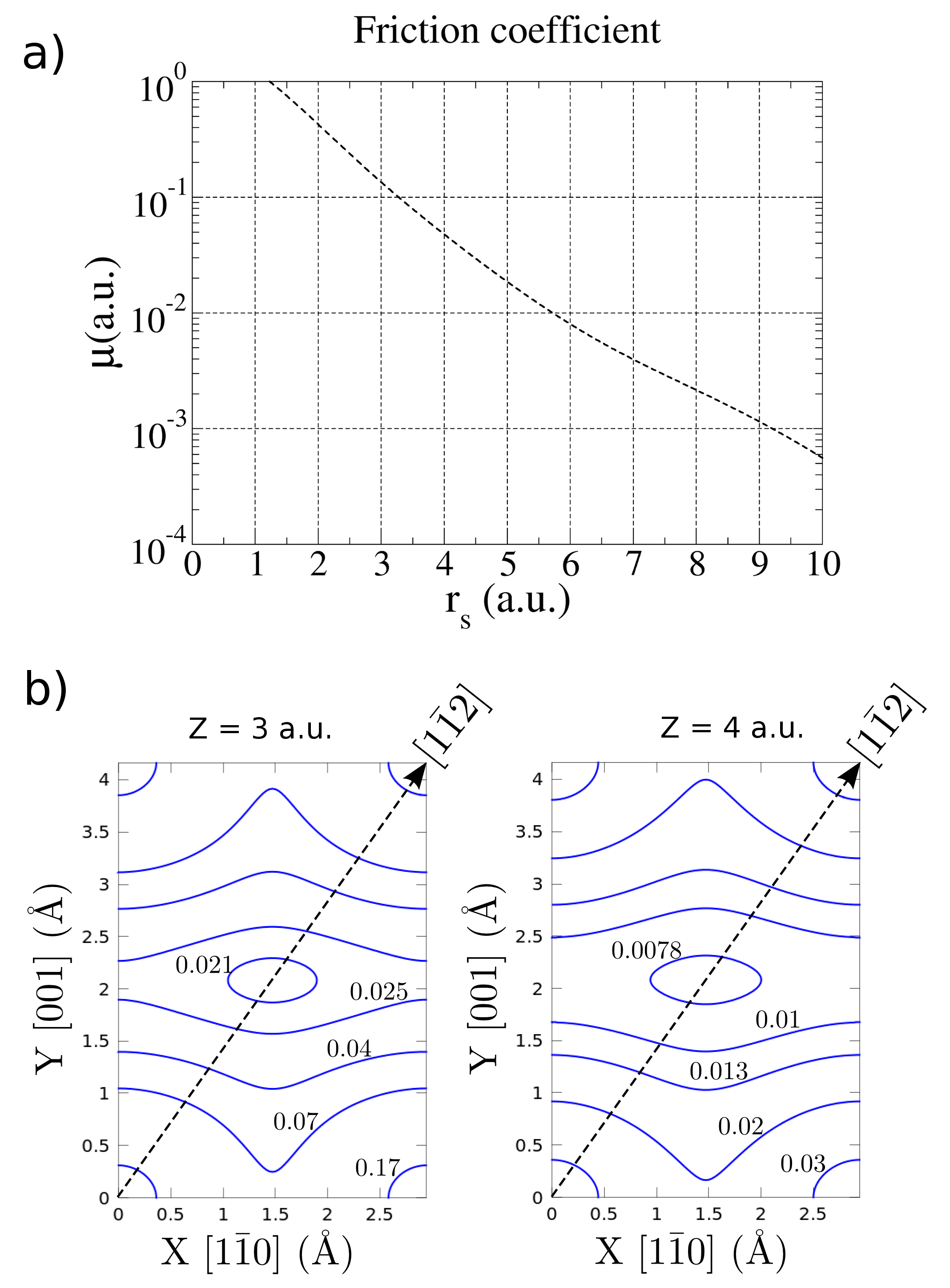
In this work we extend a previous study Rubiano14 to investigate the energy lost by 3He atoms grazingly colliding with Ag() along the , and channels. Impact energies ranging from keV to keV and perpendicular energies varying from eV to eV are considered, being the incidence angle measured with respect to the surface plane. Energy- and angle- resolved distributions of inelastically scattered He atoms are classically derived by solving Eq. (2) for random initial positions that vary within a surface area equal to unit cells. For all the trajectories the initial atom-surface distance is chosen equal to the lattice constant, corresponding to a region where the surface interaction is completely negligible Rubiano13 . The differential probability is calculated by considering a dense grid of , , and values (), which is used to build the cells where final momenta are assigned. The energy-loss distribution , as a function of the lost energy , is straightforwardly derived from by integrating on the solid angle . Fig. 1 (a) shows the friction coefficient for the He atom moving in an electron gas of local density , as a function of the mean electron radius , defined as . Electron density contours for two different - distances to the surface are plotted in Fig. 1 (b).
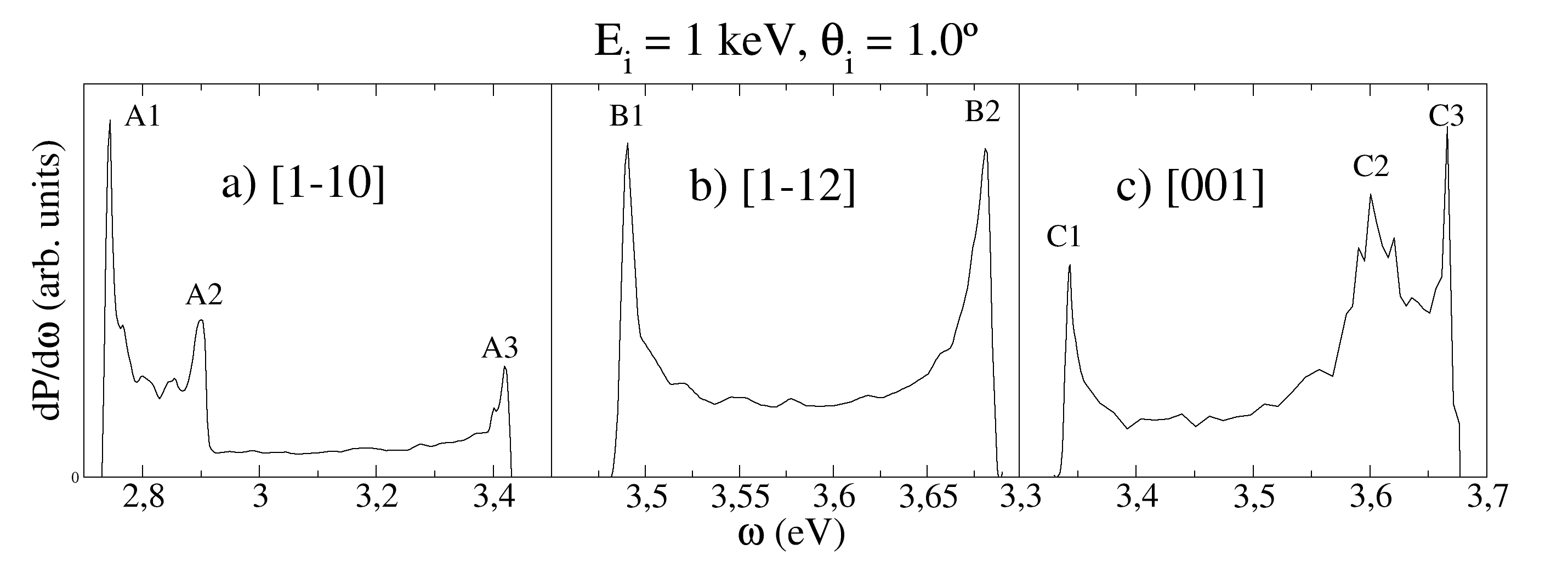
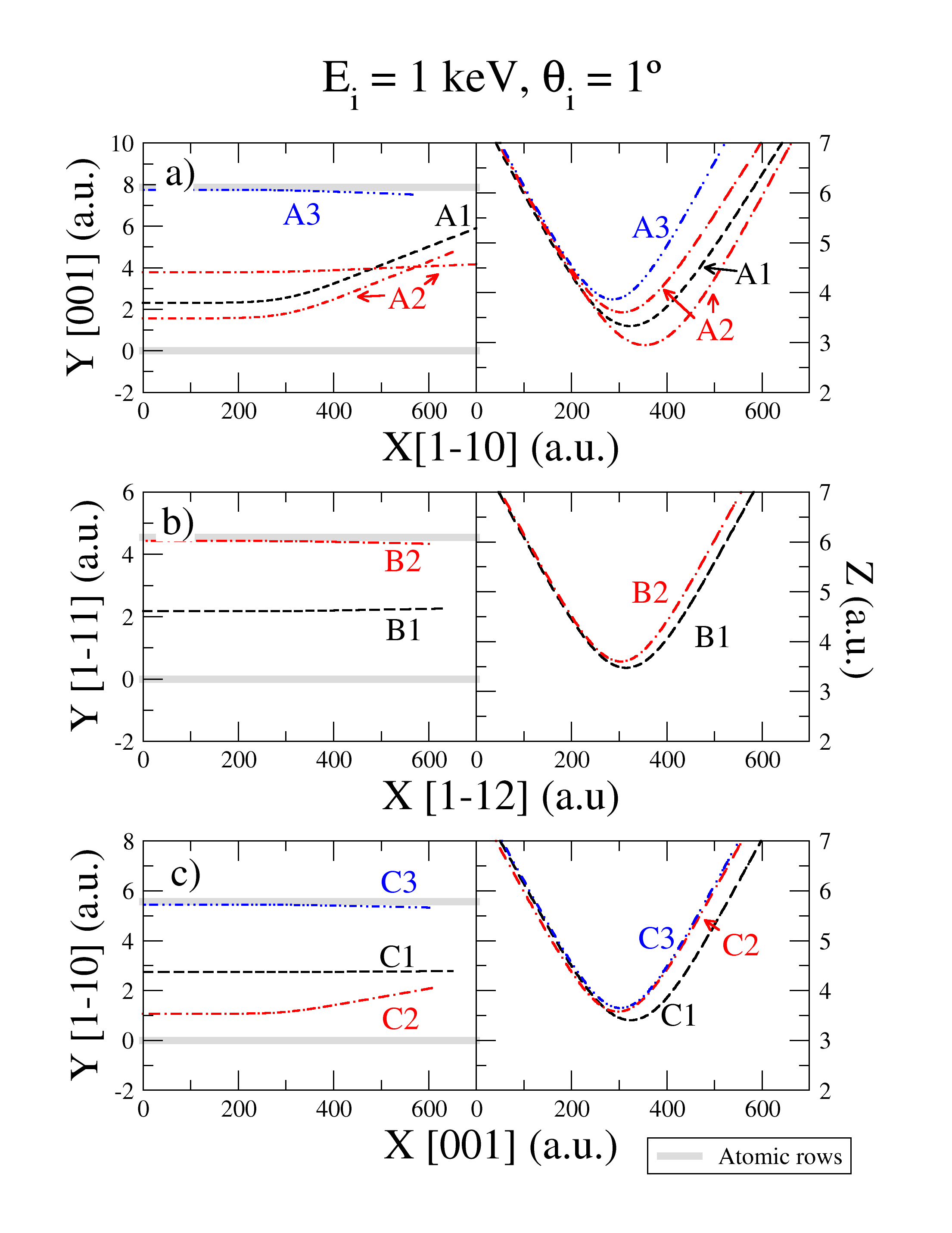
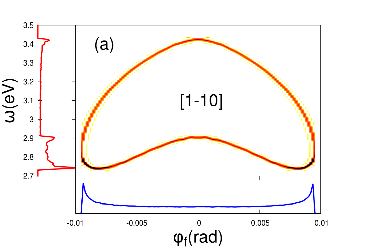
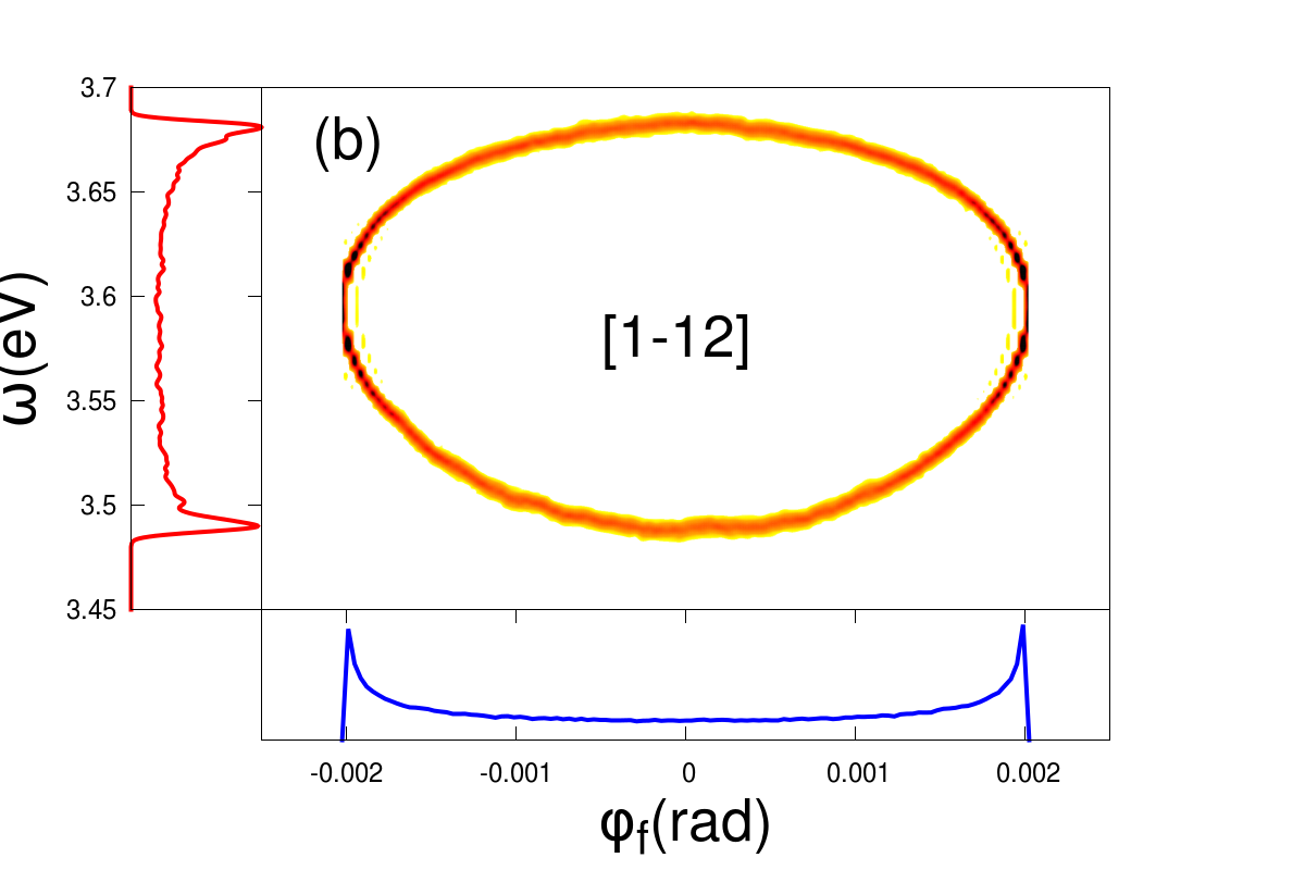
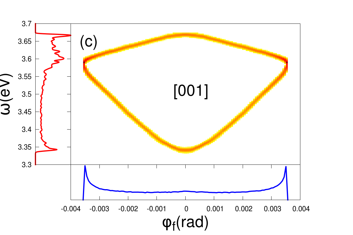
In Fig. 2 we show for keV and (that is, eV) considering the incidence directions , and . These energy-loss distributions, obtained without including the experimental spread of the incident beam in the calculations, present well defined structures with multiple peaks, resembling the energy-loss spectra reported in Ref. Moix10 . In order to identify the origin of these peaks, labeled with letters A, B, and C in Figs. 2 a), b) and c) respectively, representative trajectories contributing to them are plotted in Fig. 3. For the three incidence directions we find that every energy-loss peak is related to a defined set of projectile trajectories. For incidence along the channel (Fig. 2 (a)) the peak A1, which presents the highest intensity, is associated with trajectories that suffer strong azimuthal deviations with respect to the incidence direction, corresponding to classical rainbow scattering. Such paths probe regions with low electron density, producing the lowest energy loss of the spectrum. Instead, the trajectories that contribute to the peak A3 correspond to He atoms that move over the rows of topmost Ag atoms that form the channel, suffering almost no deviation. Even though these projectiles are the ones that least approach the surface as they do not enter the channel, they probe the region with the highest electron density, thus suffering the highest energy loss. Lastly, two different kind of trajectories contribute to the peak A2: one of them running parallel to the channel in the middle position between rows and the other running far away from the surface plane and suffering an azimuthal deflection.
A similar structure, with three peaks, is observed for incidence along the channel (Fig. 2 (c)), but in this case, the peak C2 is the one associated with rainbow scattering, while the peaks C1 and C3 are related to He atoms that move in the middle or on top of the channel rows, respectively. On the other hand, the energy-loss distribution for incidence along the channel (Fig. 2 (b)) displays a completely different structure, with only two peaks - B1 and B2 - at the extremes of the distribution. These peaks are associated with projectiles running in the middle of the channel or over the rows of topmost surface atoms, respectively. We have thus found that it is the dependence of energy loss on the kind of He trajectory that determines the multiple-peak structure in energy-loss distributions for mono-energetic incident beams (named here primary distributions). This result could be used to study the effective corrugation of the surface electronic density. However, the experimental determination of these primary energy-loss spectra would require an energy resolution better than one eV, which is not yet reachable with present experimental capabilities.
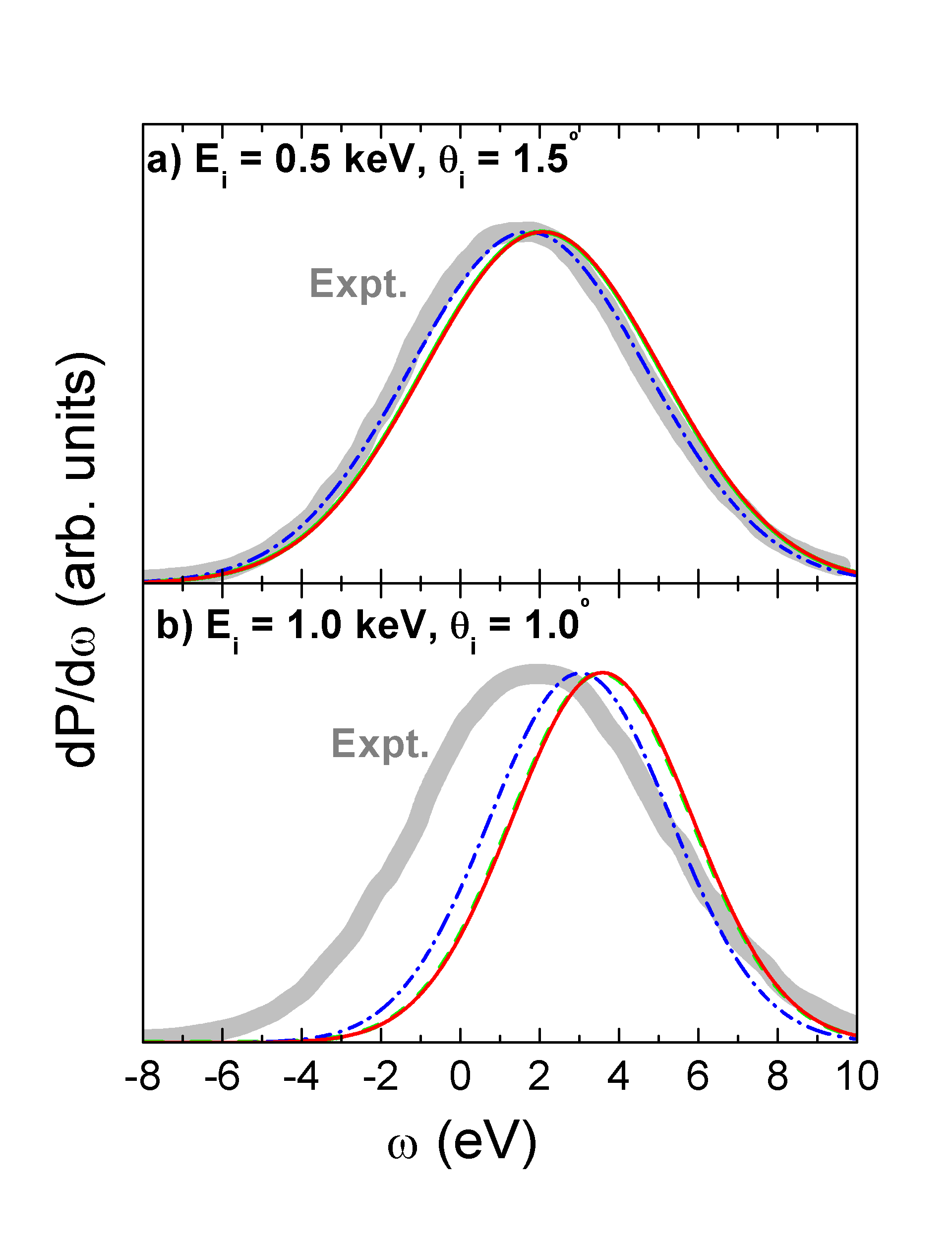
With the aim of comparing the energy-loss spectra with available experimental data Bundaleski08 ; Bundaleski11 ; note-dir0 , in Fig. 4 we plot the energy-loss distribution obtained by including the energy profile of the experimental incident beam through convolution note-conv . Two different initial conditions are considered: (a) keV, (i.e. eV) and (b) keV, (i.e. eV). In both cases, when the experimental energy dispersion is introduced in the calculation we obtain a smooth energy-loss curve, without any signature of the primary-energy loss structure. For keV the experimental curve is fairly well reproduced by the simulation, but the agreement deteriorates when the energy increases and for keV the maximum of the energy loss distribution overestimates the experimental value. Primary distributions of Fig. 2 present completely different shapes but, for incidence along the and channels they produce similar convoluted energy-loss spectra, with a mean energy loss slightly higher than the one obtained for the direction, as observed in Fig. 4. This last result is unexpected at first glance because the average electronic density probed by He atoms that move over the atomic rows of the channel is higher than the one corresponding to any of the other channels. However, since projectiles running along the or directions suffer a smaller friction in the incoming path than in the case of the direction, they can get closer to the surface thus loosing more energy in the whole trajectory. This interplay between the distance of maximum approach to the surface and the energy lost along the path is also observed for the different perpendicular energies considered in this work, as shown in Fig. 7.
In relation to the angular distribution of inelastically scattered He atoms, in all the cases it shows the usual banana shape Meyer95 , with final polar and azimuthal angles lying inside a circular annulus, characteristic of the axial channeling conditions. Due to the fact that in our model the friction force acts along the direction of the velocity, the energy loss affects mainly the component of the projectile velocity along the incidence channel. Then, initial and final energies associated with the motion normal to the channel are very similar, almost strictly verifying . Double differential probabilities, , as a function of the lost energy and the azimuthal angle , are displayed in Fig. 5 for the incidence conditions of Fig. 2. For the three channels the two-dimensional (2D) angle- and energy-loss- resolved distributions present a double peak energy-loss structure for most angles, with sharp maxima at the outermost azimuthal angles, which are associated with classical rainbow dispersion. The shape of these 2D spectra strongly varies with the incidence direction, showing energy-loss peaks associated with rainbow scattering only for the and channels. Notice that while energy-loss structures give information about the electronic density along the channel, the angular positions of rainbow peaks depend on the corrugation of the surface potential across the incidence direction Schuller04 ; Schuller07b ; Tiwald10 ; Gravielle13 . Thus, experiments in coincidence, measuring simultaneously angular and energy-loss distributions with a certainly high energy resolution, might provide useful insights on the atom-surface interaction.
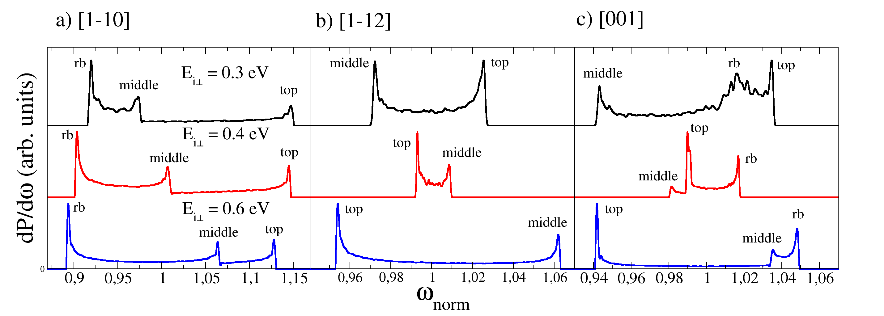
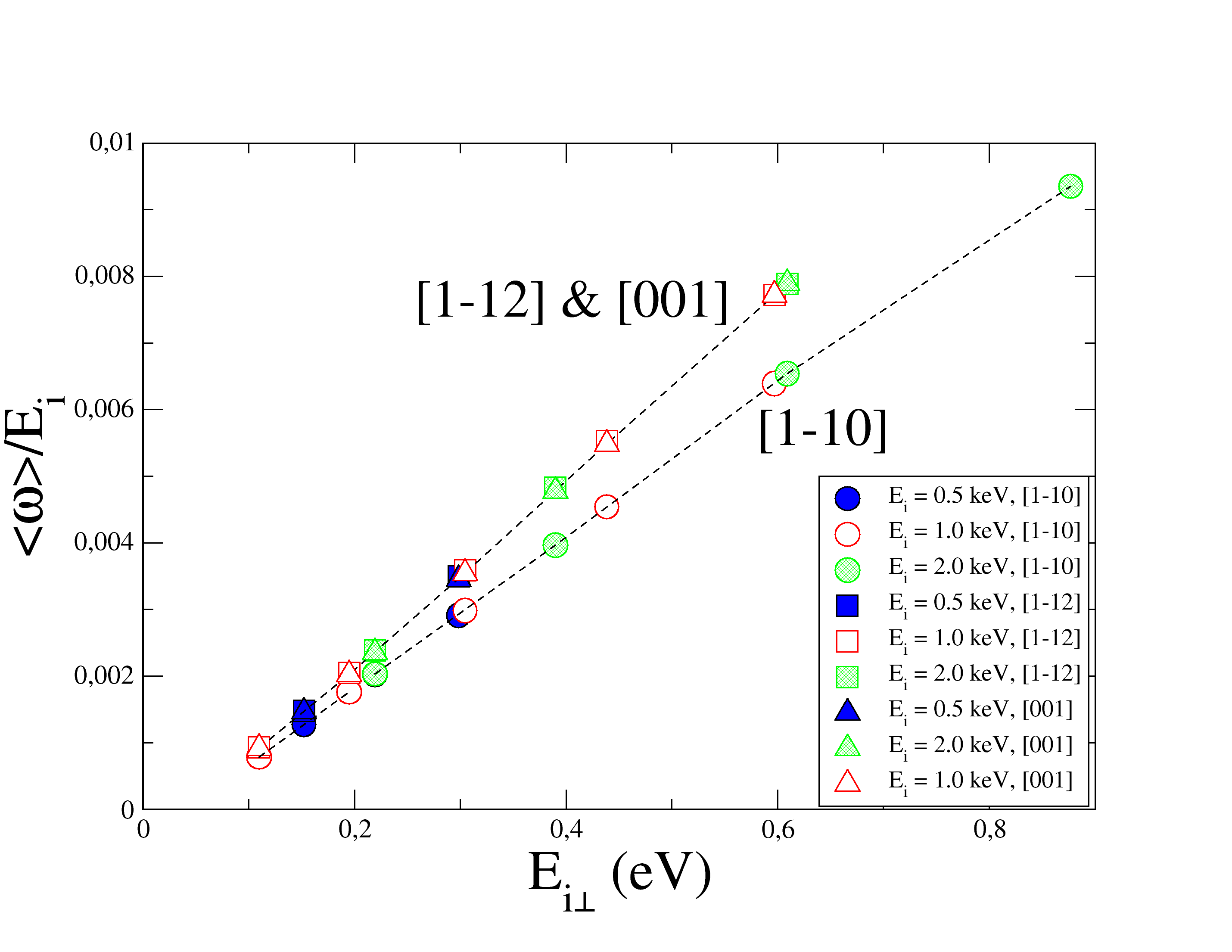
Finally, to investigate the dependence of the energy-loss on , in Fig. 6 we display primary energy-loss distributions for keV He atoms, as a function of the normalized lost energy , where denotes the mean energy loss, considering different perpendicular energies. In the figure we have labeled as top, middle and rb the peaks associated with trajectories running along top or middle-channel rows, or contributing to the rainbow angle, respectively. We found that the relative positions of the energy-loss peaks change with the perpendicular energy. Such an energy displacement is more notorious for the directions and , which present a high corrugation of the electronic density along the channel. While for the direction the type of trajectories contributing to each peak do not vary with in the considered range, for the other two directions top (middle) trajectories contribute to the region of low (high) or high (low) lost energies, depending on the perpendicular energy. This fact is again related to the strong corrugation of the electronic density along these channels. In addition, the mean energy loss for a given incidence direction, normalized with the impact energy , shows a linear behavior as a function of the perpendicular energy, increasing as augments, as observed in Fig. 7. In all the cases, mean energy loss values for the channels and are similar, being higher than the ones corresponding to the channel, as discussed above.
IV CONCLUSIONS
We have studied the energy lost by helium atoms after grazingly colliding with a silver surface along low indexed crystallographic directions. The distribution of inelastically scattered atoms was obtained within a semi-classical formalism that incorporates a friction force in the classical dynamics equations allowing for the calculation of the trajectory-dependent energy loss. For the , and channels we found that energy-loss distributions corresponding to mono-energetic incidence beams display well defined structures, with several sharp maxima that are related to trajectories that probe regions with different densities and potential energies. However, these energy-loss structures are completely blurred out by the experimental spread of the incident beam, which produces a broad energy-loss distribution with only one maximum. Even though these last distributions are in fairly good agreement with available experimental data Bundaleski08 ; Bundaleski11 , experiments in coincidence measuring simultaneously angle- and energy-loss- resolved spectra with a high energy resolution would be necessary to shed light on the findings of the present work.
Acknowledgements.
Authors are kindly grateful to Philippe Roncin for his helpful suggestions. C.R.R and M.S.G. acknowledge financial support from CONICET, UBA, and ANPCyT of Argentina. G.A.B. acknowledges financial support by ANPCyT and is also thankful to Dr. H.F. Busnengo, Dr. J.D. Führ and Dr. M.L. Martiarena regarding the PES calculation. J. I. J. acknowledges financial support by the Basque Departamento de Educación, Universidades e Investigación, the University of the Basque Country UPV/EHU (Grant No. IT-756-13) and the Spanish Ministerio de Ciencia e Innovación (Grant No. FIS2010-19609-C02-02)References
- (1) A. Robin et al., Phys. Rev. B 67 (2003) 165409; A. Robin and W. Heiland, Nucl. Instrum. Meth. Phys. Res. B 230 (2005) 165.
- (2) A.J. García and J.E. Miraglia, Phys. Rev. A 74 (2006) 012902.
- (3) J.E. Valdés et al., Phys. Rev. A 78 (2008) 032902.
- (4) L. Chen, J. Shen, J.E. Valdés, P. Vargas, and V.A. Esaulov, Phys. Rev. A 83 (2011) 032901.
- (5) A. Schüller, S. Wethekam, and H. Winter, Phys. Rev. Lett. 98 (2007) 016103.
- (6) P. Rousseau, H. Khemliche, A.G. Borisov, and P. Roncin, Phys. Rev. Lett. 98 (2007) 016104.
- (7) H. Winter and A. Schüller, Prog. Surf. Sci. 86 (2011) 169 and references therein.
- (8) N. Bundaleski, H. Khemliche, P. Soulisse, and P. Roncin, Phys. Rev. Lett. 101 (2008) 177601.
- (9) M. Busch, A. Schüller, S. Wethekam, and H. Winter, Surf. Sci. 603 (2009) L23.
- (10) H. Khemliche, P. Rousseau, P. Roncin, V.H. Etgens, and F. Finocchi, Appl. Phys. Lett. 95 (2009) 151901.
- (11) A. Schüller, M. Busch, S. Wethekam, and H. Winter, Phys. Rev. Lett 102 (2009) 017602.
- (12) J. Seifert et al., Phys. Rev. B 82 (2010) 035436.
- (13) J. Seifert, M. Busch, E. Meyer, and H. Winter, Phys. Rev. Lett. 111 (2013) 137601.
- (14) J. Lienemann et al., Phys. Rev. Lett. 106 (2011) 067602.
- (15) M. Busch, J. Lienemann, J. Seifert, A. Schüller, and H. Winter, Vacuum 86 (2012) 1618.
- (16) J. Lienemann et al., Nucl. Instrum. Meth. Phys. Res. B 315 (2013) 30.
- (17) C. A. Ríos Rubiano et al., Phys. Rev. A 87 (2013) 012903.
- (18) H. Khemliche, N. Bundaleski, P. Soulisse, and P. Roncin, Nucl. Instrum. Meth. Phys. Res. B 267 (2009) 620.
- (19) N. Bundaleski, P. Soulisse, A. Momeni, H. Khemliche, and P. Roncin, Nucl. Instrum. Meth. Phys. Res. B 269 (2011) 1216.
- (20) M.S. Gravielle and J.E. Miraglia, Nucl. Instrum. Meth. Phys. Res. B 258 (2007) 21.
- (21) J.I. Juaristi, M. Alducin, R. Díez Muiño, H.F. Busnengo and A. Salin, Phys. Rev. Lett. 100 (2008) 116102.
- (22) P. Giannozzi et al., J. Phys. Condens. Matter 21 (2009) 395502.
- (23) H.F. Busnengo, A. Salin and W. Dong, J. Chem. Phys. 112 (2000) 7641.
- (24) A. Robin, W. Heiland, J. Jensen, J.I. Juaristi, and A. Arnau, Phys. Rev. A 64 (2001) 052901.
- (25) S. Lederer, H. Winter and HP. Winter, Nucl. Instrum. Meth. Phys. Res. B 258 (2007) 87.
- (26) R.H. Ritchie, Phys. Rev. 114 (1959) 644.
- (27) I. Goikoetxea, J.I. Juaristi, M. Alducin, and R. Díez Muiño, J. Phys.: Condens. Matter 21 (2009) 264007.
- (28) L. Martin-Gondre et al., Phys. Rev. Lett. 108 (2012) 096101.
- (29) M. Alducin, R. Díez Muiño, and J.I. Juaristi, in Dynamic of Gas-Surface Collisions, Springer Series in Surface Science 50 (2013), p. 371.
- (30) P.M. Echenique , R.M. Nieminen, and R.H. Ritchie, Solid State Commun. 37 (1981) 779.
- (31) E. Zaremba, J.H. Rose, L.M. Sander, and H.B. Shore, J. Phys. F: Met. Phys. 7, 1763 (1977).
- (32) C.A. Ríos Rubiano, G.A. Bocan, J.I. Juaristi, and M.S. Gravielle, submitted to Phys. Rev. A.
- (33) J.M. Moix, E. Pollak, and S. Miret-Artés, Phys. Rev. Lett. 104 (2010) 116103.
- (34) P. Roncin, private communication.
- (35) Theoretical results were convoluted with a Gaussian function whose parameters were extracted from the experiment.
- (36) F.W. Meyer, L. Folkerts, and S. Schippers, Nucl. Instrum. Meth. Phys. Res. B 100 (1995) 366.
- (37) A. Schüller et al., Phys. Rev. A 69 (2004) 050901(R).
- (38) A. Schüller and H. Winter, Nucl. Instrum. Meth. Phys. Res. B 261 (2007) 578.
- (39) P. Tiwald et al., Phys. Rev. B 82 (2010) 125453.
- (40) M.S. Gravielle, J.E. Miraglia, A. Schüller, and H. Winter, Nucl. Instrum. Meth. Phys. Res. B 317 (2013) 77.
- (41) Note that the directions reported in Ref. Bundaleski08 correspond to thermal energy atom scattering (TEAS) notations, i.e. to the direction probed by the beam rather than the direction of the beam itself, both directions being perpendicular to each other. The same notation was used for energy loss measurements (P. Roncin, private communication).