∗Hailu Luo email address: hailuluo@hnu.edu.cn
†Shuangchun Wen email address:
scwen@hnu.edu.cn
Photonic spin Hall effect for precision metrology
Abstract
The photonic spin Hall effect (SHE) is generally believed to be a result of an effective spin-orbit coupling, which describes the mutual influence of the spin (polarization) and the trajectory of the light beam. The photonic SHE holds great potential for precision metrology owing to the fact that the spin-dependent splitting in photonic SHE are sensitive to the physical parameter variations of different systems. Remarkably, using the weak measurements, this tiny spin-dependent shifts can be detected with the desirable accuracy so that the corresponding physical parameters can be determined. Here, we will review some of our works on using photonic SHE for precision metrology, such as measuring the thickness of nanometal film, identifying the graphene layers, detecting the strength of axion coupling in topological insulators, and determining the magneto-optical constant of magnetic film.
keywords:
photonic spin Hall effect, spin-orbit coupling, weak measurements1 INTRODUCTION
The photonic spin Hall effect (SHE) manifests itself as spin-dependent splitting of left- and right-handed circularly polarized components when a spatially confined light beam is reflected or transmitted at an interface [1, 2, 3]. The photonic SHE can be regarded as a direct optical analogy of SHE in an electronic system, in which the spin photons play the role of the spin charges and a refractive index gradient plays the role of the applied electric field. This interesting phenomenon is generally believed to be a result of an effective spin-orbit coupling, which describes the mutual influence of the spin (polarization) and the trajectory of the light beam. There are two types of geometric phases playing the important role in photonic SHE: the spin redirection Berry phase and the Pancharatnam-Berry phase [4, 5]. The photonic SHE is currently attracting growing attention and has been intensively investigated in different physical systems such as optical physics [6, 7, 8, 9, 10, 11], high-energy physics [12, 13], semiconductor physics [14, 15], and plasmonics [16, 17, 18, 19, 20].
Remarkably, the spin-dependent splitting in photonic SHE are sensitive to the physical parameter variations of different systems, and therefore it holds great potential applications in precision metrology. However, the spin-dependent splitting of photonic SHE in these systems is just a few tens of nanometers so that the actual equipment can not distinguish it directly. We resolve this problem by using the precise signal enhancement technique called quantum weak measurements which has attracted a lot of attention [21, 22, 23, 24, 25, 26, 27, 28, 29]. The idea of weak measurements can be described as follows: if we initially select the quantum system with a well-defined preselection state, the corresponding large expectation values can be obtained with a suitable postselection state, which makes the eigenvalues to be clearly distinguished [30, 31, 32]. Using the quantum weak measurement, the photonic SHE can be detected with the desirable accuracy.
In this paper, we will review some of our recent works on using photonic SHE for precision metrology, such as measuring the thickness of nanometal film [33], identifying the graphene layers [34], detecting the strength of axion coupling in topological insulators [35], and determining the magneto-optical constant of magnetic film. We find that the physical parameter variations in these systems can effectively change the spin-dependent displacements. We firstly establish the quantitative relationship between the spin-dependent shifts and the physical parameters. After detecting the spin-dependent displacements with weak measurement method, we can accurately determine these physical parameters. The rest of the paper is organized as follows. In Sec. 2, we establish a general propagation model to describe the photonic SHE on the sample. In the Sec. 3, we firstly introduce the weak measurements experimental process. Then, we will briefly review our recent works on using photonic SHE for precision metrology. Finally, a conclusion is given in Sec. 4.
2 GENERAL PROPAGATION MODEL
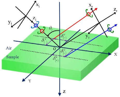
Figure 1 schematically draws the photonic SHE of light beam reflection from a sample interface. We firstly establish the quantitative relationship between the spin-dependent shifts in photonic SHE and the physical parameters of sample. Here, the physical parameters include the thickness of nanometal film, graphene’s layers, axion angle in topological insulators, and the magneto-optical constant of magnetic film. The incident polarization states are chosen as and . In the spin basis, the horizontal and vertical polarization states can be expressed as and . Corresponding, the states of reflected beam can be obtained:
| (1) |
| (2) |
In the above equations, , . We should note that, as for the topological insulators, the states of reflected beam have different forms. The detailed discussions can be found in our previous work [35].
The photonic SHE manifests for the spin-dependent splitting of left- and right-handed circularly polarized components. We consider the spin separation in the x direction (in-plane shift) and y direction (transverse shift). In the following, we calculate the shifts of these two spin components. The wavefunction of reflected photons is composed of the packet spatial extent and the polarization description :
| (3) |
After photons reflection from the sample interface, the initial state evolve into the final state . As a result of spin-orbit coupling, the shifts of the two spin components compared to the geometrical-optics prediction are given by
| (4) |
Here, we suppose the is a Gaussian wave function. Calculating the reflected shifts of photonic SHE requires the explicit solution of the boundary conditions at the sample interfaces. As for the nanometal film and graphene film, we need to deal with the multilayer structure model. Thus, we need to know the generalized Fresnel reflection of the sample,
| (5) |
Here, , and is the Fresnel reflection coefficients at the first interface and second interface, respectively. and represent the refractive index and the thickness of the nanometal film and graphene film, respectively.
3 PHOTONIC SPIN HALL EFFECT FOR PRECISION METROLOGY
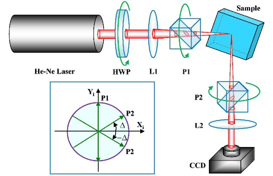
We have established the relationship between the physical parameters of sample and the spin-dependent displacements induced by photonic SHE. Next, we will use the weak measurements method to detect the this tiny shifts. After detecting the spin-dependent displacements, we can accurately determine these physical parameters. As shown in Fig. 2, our experimental setup is similar to that in Ref [36]. Our samples are the usual BK7 prism prepared with the nanometal film, graphene film, topological insulators, and magnetic film. A Gauss beam generated by He-Ne laser is firstly focused by the lens (L1) and experiences preselection in the state = or with the polarizer P1. When the light beam reflects from the sample interface, the photonic SHE happens allowing for the left- and right-handed circularly polarized components splitting in the x and y directions corresponding to the in-plane and transverse displacements. This process can be seen as the weak interaction allowing for the coupling between the observable and the meter. And then the beam passes through the second polarizer P2 preparing for the postselection state or . At the surface of the second polarizer, the two spin components experience destructive interference making the enhanced shift in the meter much larger than the initial one. Calculating the reflected field distribution yields the amplified shifts of photonic SHE. After passing through the second lens (L2), a CCD is used to capture the optical signal and measure the amplified shifts. The process discussed above is called the weak value amplification and is the postselection angle. We should note that the imaginary weak value also corresponds to a shift of the meter in momentum space, which leads to the possibility of even larger enhancements following the beam free evolution. This process can be seen as propagation amplification that produces the amplified factor F. In the following, we will review some of our recent works on using photonic SHE for precision metrology.
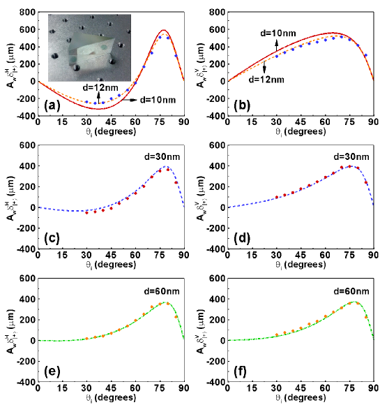
In the fist work, we have used the photonic SHE to measure the thickness of nanometal film [33]. We establish a general propagation model to describe the photonic SHE on a nanometal film and reveal the impact of the corresponding physical parameters on the spin-dependent splitting in photonic SHE. It is well known that the photonic SHE manifests itself as the spin-orbit coupling. We find that the spin-orbit coupling in the photonic SHE can be effectively modulated by adjusting the thickness of the metal film. A similar effect can also be observed in layered nanostructures, in which the transverse displacement changes periodically with the air gap increasing or decreasing. Additionally, the transverse displacement is sensitive to the thickness of metal film in certain range for horizontal polarization light beam. We also note tha a large negative transverse shift can be observed.
Next, we focus our attention on the weak measurements experiment. Here, the BK7 glass substrate coated Ag film is chosen as our sample (with three different thickness , and ). The experimental setup is described in the above contents. We measure the displacements of photonic SHE on the nanometal film every from to in the case of horizontal and vertical polarization, respectively. Limited by the large holders of the lens, polarizers and He-Ne laser, displacements at small incident angles were not measured. It should be noted that the experimental results are in good agreement with the theoretical ones when the film thicknesses are and . However, we observe a small deviation when the thickness is . Note that the thickness of the nanometal film has an error limited by the experimental condition. When the thickness reaches to , the SHE of light is very sensitive to the error. It is the reason why there is a small deviation between the experimental and the theoretical data. From the experimental results, we can conclude that the actual thickness of the film is about (Fig. 3). These findings provide a pathway for modulating the photonic SHE and thereby open the possibility of developing nanophotonic applications.
We also propose using the photonic SHE to identify the graphene layers [34]. The quick and convenient technique for identifying the layer numbers of graphene film is important for accelerating the study and exploration of graphene material. There have many methods for determining the layer numbers of graphene film, yet existing limitation. For example, atomic force microscopy technique is the straight way to determine the layer numbers of graphene. But this method shows a slow throughput and may induce damage to the sample. Unconventional quantum Hall effects [37] are usually used to distinguish one layer and two layers graphene from multiple layers. Raman spectroscopy [38] shows characteristic for quick and nondestructive measuring the layer numbers of graphene. However, it is not obvious to tell the differences between bilayer and a few layers of graphene films [39]. We find that the photonic SHE can serve as a useful metrological tool for characterizing the structure parameters’ variations of nanostructure due to their sensitive dependence. So, the photonic SHE may have a potential to determine the layer numbers of graphene.
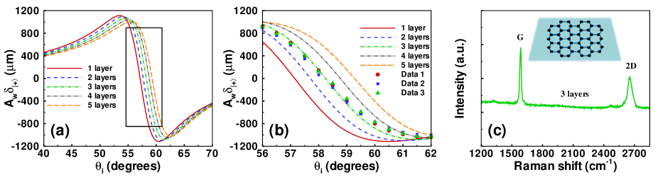
We establish the relationship between the spin-dependent displacements and the graphene layer numbers. The weak measurements method has been used to detect the transverse shifts, and so the graphene layer numbers can be obtained. However, there exists two unknown parameters (refractive index and layer numbers of graphene) to be identified. Before identifying the graphene layers, we need to choose the suitable refractive index parameter of graphene. We choose one suitable refractive index according from the work of Bruna and Borini [40]. Here, the refractive index of graphene is about at 633 nm. Through measuring the spin-dependent shifts of photonic SHE on the graphene film, we prove that this refractive index is suitable for actual situation. Using the suitable refractive index n= at 633 nm, we can identify the layer numbers of an unknown graphene film. It should be noted that we cannot fabricate the graphene film with the precise layer numbers when the graphene film has more than two layers. We just know the approximate layer numbers ranging from three to five layers. We want to determine the actual layer numbers of this graphene film. As shown in Fig. 4, we measure the transverse displacements with the incident angle changing from to . To avoid the influence of impurities and other surface quality factors of graphene film, we carried out the experiments for three different areas of the graphene sample. It is concluded that the actual layer numbers of the film is three.
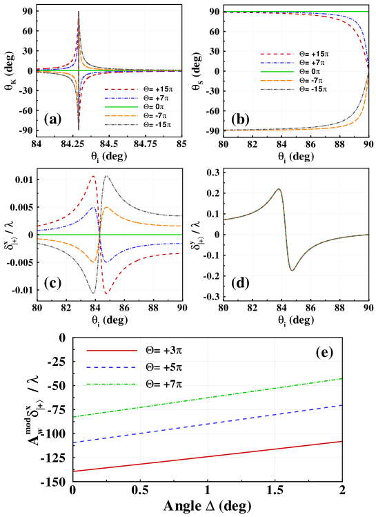
Recently, the topological insulators (TIs) material has aroused tremendous interest [41, 42]. It has gapless helical surface states owing to the topological protection of the time-reversal symmetry and represents a full energy gap in the bulk [43, 44]. In a recent paper, we theoretically investigate the photonic SHE of a Gaussian beam reflected from the interface between air and topological insulators (TIs) [35]. We reveal that the spin-orbit coupling effect in TIs can be routed by adjusting the axion angle variations. It is shown that the magneto-optical Kerr effect can be significantly altered due to the axion coupling and shows close relationship with spin-dependent splitting in photonic SHE [Fig. 5(a) and 5(b)]. We find that, unlike the transverse spin-dependent splitting, the in-plane one is sensitive to the axion angle [Fig. 5(c) and 5(d)]. Due to the the limitation of experimental condition, we theoretically propose a weak measurement method to determine the strength of axion coupling by probing the in-plane splitting of the photonic SHE.
The incident beam is focused by the lens and is preselected in the horizontal polarization, and then it is postselected in the polarization state with ( is the amplified angle). The relevant amplitude of the reflected field at a plane can be obtained, allowing for calculation of amplified displacement. The theoretical amplified shifts are shownin Fig. 5(e). Here the incident angle is fixed to . Then we obtain the amplified displacements varying with axion angle and amplified angle. For a fixed angle , the amplified in-plane shifts change clearly with the different axion angles, and so we can measure the axion coupling effect by determining the in-plane displacements with weak measurements. These findings offer us potential methods for determining the strength of the axion coupling and provide new insight into the interaction of light with TIs.
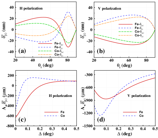
We have also used the photonic SHE for determining the magneto-optical constant of magnetic film and the preliminary results can be seen in Fig. 6. The magneto-optical constant is an important parameter for the study and exploration of magnetic material. The relationship between the spin-dependent splitting in photonic SHE and the magneto-optical constant of magnetic film is established. Here, we choose the Fe and Co as our samples, which have different magneto-optical constants (= [45, 46] and = [47] at 633 nm). From the Fig. 6(a) and 6(b), we can see that the spin-dependent displacements are sensitive to the magneto-optical constants of different magnetic materials. So, we can determine the magneto-optical constants by measuring the spin-dependent splitting of photonic SHE. In our experiment, the weak measurements has been used to detect this tiny shifts [the preliminary theoretical results are shown in Fig. 6(c) and 6(d)]. We also find that the amplified spin shifts are sensitive to the variations of magneto-optical constants (Fe and Co). Importantly, the Kerr rotation angle in magneto-optical Kerr effect can also be detected by using this way, which shows higher accuracy than the normal extinction method. In fact, our experiment is in progress and the manuscript is in preparation.
4 CONCLUSIONS
In summary, we have reviewed our recent works on using photonic SHE for precision metrology. After establishing the quantitative relationship between the spin-dependent shifts in photonic SHE and the physical parameters in different systems, we have used the weak measurements methods for measuring the thickness of nanometal film, identifying the graphene layers, detecting the strength of axion coupling in topological insulators, and determining the magneto-optical constant of magnetic film. These findings provide a practical application for photonic SHE and thereby open the possibility of developing spin-based nanophotonic device.
Acknowledgements.
This research was partially supported by the National Natural Science Foundation of China (Grants Nos. 61025024 and 11274106) and Hunan Provincial Innovation Foundation for Postgraduate (Grant No. CX2013B130).References
- [1] M. Onoda, S. Murakami, and N. Nagaosa, “Hall effect of light,” Phys. Rev. Lett. 93, 083901 (2004).
- [2] K. Y. Bliokh and Y. P. Bliokh, “Conservation of angular momentum, transverse shift, and spin Hall effect in reflection and refraction of an electromagnetic wave packet,” Phys. Rev. Lett. 96, 073903 (2006).
- [3] O. Hosten and P. Kwiat, “Observation of the spin Hall effect of light via weak measurements,” Science 319, 787 (2008).
- [4] K. Y. Bliokh, A. Niv, V. Kleiner, and E. Hasman, “Geometrodynamics of spinning light,” Nature Photon. 2, 748 (2008).
- [5] K. Y. Bliokh, Y. Gorodetski, V. Kleiner, and E. Hasman, “Coriolis effect in optics: Unified geometric phase and spin-Hall effect,” Phys. Rev. Lett. 101, 030404 (2008).
- [6] A. Aiello and J. P. Woerdman, “Role of beam propagation in Goos-Hänchen and Imbert-Fedorov shifts,” Opt. Lett. 33, 1437 (2008).
- [7] H. Luo, S. Wen, W. Shu, Z. Tang, Y. Zou, and D. Fan, “Spin Hall effect of a light beam in left-handed materials,” Phys. Rev. A 80, 043810 (2009).
- [8] Y. Qin, Y. Li, H. He, and Q. Gong, “Measurement of spin Hall effect of reflected light,” Opt. Lett. 34, 2551 (2009).
- [9] N. Hermosa, A. M. Nugrowati, A. Aiello, and J. P. Woerdman, “Spin Hall effect of light in metallic reflection,” Opt. Lett. 36, 3200 (2011).
- [10] H. Luo, X. Ling, X Zhou, W. Shu, S. Wen, and D. Fan, “Enhancing or suppressing the spin Hall effect of light in layered nanostructures,” Phys. Rev. A 84, 033801 (2011).
- [11] X. Ling, X. Zhou, W. Shu, H. Luo, and S. Wen, “Realization of tunable photonic spin Hall effect by tailoring the Pancharatnam-Berry phase,” Sci. Rep. 4, 5557 (2014).
- [12] P. Gosselin, A. Bérard, and H. Mohrbach, “Spin Hall effect of photons in a static gravitational field,” Phys. Rev. D 75, 084035 (2007).
- [13] C. A. Dartora, G. G. Cabrera, K. Z. Nobrega, V. F. Montagner, M. H. K. Matielli, F. K. R. de Campos, and H. T. S. Filho, “Lagrangian-Hamiltonian formulation of paraxial optics and applications: Study of gauge symmetries and the optical spin Hall effect,” Phys. Rev. A 83, 012110 (2011)
- [14] J.-M. Ménard, A. E. Mattacchione, M. Betz, and H. M. van Driel, “Imaging the spin Hall effect of light inside semiconductors via absorption,” Opt. Lett. 34, 2312 (2009).
- [15] J.-M. Ménard, A. E. Mattacchione, H. M. van Driel, C. Hautmann, and M. Betz, “Ultrafast optical imaging of the spin Hall effect of light in semiconductors,” Phys. Rev. B 82, 045303 (2010).
- [16] N. Shitrit, I. Bretner, Y. Gorodetski, V. Kleiner, and E. Hasman, “Optical Spin Hall Effects in Plasmonic Chains,” Nano Lett. 11, 2038 (2011).
- [17] Y. Gorodetski, K. Y. Bliokh, B. Stein, C. Genet, N. Shitrit, V. Kleiner, E. Hasman, and T. W. Ebbesen, “Weak Measurements of Light Chirality with a Plasmonic Slit,” Phys. Rev. Lett. 109, 013901 (2012).
- [18] N. Shitrit, I. Yulevich, E. Maguid, D. Ozeri, D. Veksler, V. Kleiner, and E. Hasman, “Spin-Optical metamaterial route to spin-Controlled photonics,” Science 340, 724 (2013).
- [19] X. Yin, Z. Ye, J. Rho, Y. Wang, and X. Zhang, “Photonic spin Hall effect at metasurfaces,” Science 339, 1405 (2013).
- [20] P. V. Kapitanova, P. Ginzburg , “Photonic spin Hall effect in hyperbolic metamaterials for polarization-controlled routing of subwavelength modes,” Nat. Commun. 5, 3226 (2014).
- [21] Y. Aharonov, D. Z. Albert, and L. Vaidman, “How the result of a measurement of a component of the spin of a spin -1/2 particle can turn out to be 100,” Phys. Rev. Lett. 60, 1351 (1988).
- [22] N. W. M. Ritchie, J. G. Story, and R. G. Hulet, “Enhanced and switchable spin Hall effect of light near the Brewster angle on reflection,” Phys. Rev. Lett. 66, 1107 (1991).
- [23] P. B. Dixon, D. J. Starling, A. N. Jordan, and J. C. Howell, “Ultrasensitive beam deflection measurement via interferometric weak value amplification,” Phys. Rev. Lett. 102, 173601 (2009).
- [24] J. S. Lundeen, B. Sutherland, A. Patel, C. Stewart, and C. Bamber, “Direct measurement of the quantum wavefunction,” Nature (London) 474, 188 (2011).
- [25] S. Kocsis, B. Braverman, S. Ravets, M. J. Stevens, R. P. Mirin, L. K. Shalm, and A. M. Steinberg, “Observing the average trajectories of single photons in a Two-Slit interferometer,” Science 332, 1170 (2011).
- [26] J. Dressel, M. Malik, F. M. Miatto, A. N. Jordan, and R. W. Boyd, “Colloquium: Understanding quantum weak values: Basics and applications,” Rev. Mod. Phys. 86, 307 (2014).
- [27] A. N. Jordan, J. Martínez-Rincón, and J. C. Howell, “Technical advantages for weak-value amplification: When less is more,” Phys. Rev. X 4, 011031 (2014).
- [28] G. C. Knee and E. M. Gauger, “When amplification with weak values fails to suppress technical noise,” Phys. Rev. X 4, 011032 (2014).
- [29] X. Zhou, X. Li, H. Luo, and S. Wen, “Optimal preselection and postselection in weak measurements for observing photonic spin Hall effect,” Appl. Phys. Lett. 104, 051130 (2014).
- [30] R. Jozsa, “Complex weak values in quantum measurement,” Phys. Rev. A 76, 044103 (2007).
- [31] M. R. Dennis and J. B. Götte, “The analogy between optical beam shifts and quantum weak measurements,” New J. Phys. 14, 073013 (2012).
- [32] A. Di Lorenzo, “Weak values and weak coupling maximizing the output of weak measurements,” Ann. Phys. 345, 178 (2014).
- [33] X. Zhou, Z. Xiao, H. Luo, and S. Wen, “Experimental observation of the spin Hall effect of light on a nanometal film via weak measurements,” Phys. Rev. A 85, 043809 (2012).
- [34] X. Zhou, X. Ling, H. Luo, and S. Wen, “Identifying graphene layers via spin Hall effect of light,” Appl. Phys. Lett. 101, 251602 (2012).
- [35] X. Zhou, J. Zhang, X. Ling, S. Chen, H. Luo, and S. Wen, “Photonic spin Hall effect in topological insulators,” Phys. Rev. A 88, 053840 (2013).
- [36] H. Luo, X. Zhou, W. Shu, S. Wen, and D. Fan, “Enhanced and switchable spin Hall effect of light near the Brewster angle on reflection,” Phys. Rev. A 84, 043806 (2011).
- [37] Y. B. Zhang, Y. W.Tan, H. L. Stormer, and P. Kim, “Experimental observation of the quantum Hall effect and Berry’s phase in graphene,” Nature 438, 201 (2005).
- [38] A. Gupta, G. Chen, P. Joshi, S. Tadigadapa, and P. C. Eklund, “Raman Scattering from high-frequency phonons in supported n-graphene layer films,” Nano Lett. 6, 2667 (2006).
- [39] Z. H. Ni, H. M. Wang, J. Kasim, H. M. Fan, T. Yu, Y. H. Wu, Y. P. Feng, and Z. X. Shen, “Graphene thickness determination using reflection and contrast spectroscopy,” Nano Lett. 7, 2758 (2007).
- [40] M. Bruna and S. Borini, “Optical constants of graphene layers in the visible range,” Appl. Phys. Lett. 94, 031901 (2009).
- [41] X. L. Qi and S. C. Zhang, “The quantum spin Hall effect and topological insulatorss,” Phys. Today 63, No. 1, 33 (2010).
- [42] J. E. Moore, “Topological insulators: The next generation,” Nature Phys. 5, 378 (2009).
- [43] L. Fu, C. L. Kane, and E. J. Mele, “Topological insulators in three dimensions,” Phys. Rev. Lett. 98, 106803 (2007).
- [44] J. Maciejko, X. L. Qi, H. D. Drew, and S. C. Zhang, “Topological quantization in units of the fine structure constant,” Phys. Rev. Lett. 105, 166803 (2010).
- [45] P. B. Johnson and R. W. Christy, “Optical constants of transition metals: Ti, V, Cr, Mn, Fe, Co, Ni, and Pd,” Phys. Rev. B 9, 5056 (1974).
- [46] Z. J. Yang and M. R. Scheinfein, “Combined three-axis surface magqeto-optical Kerr effects in the study of surface and ultrathin-film magnetism,” J. Appl. Phys. 74, 6810 (1993).
- [47] R. M. Osgood III, K. T. Riggs, A. E. Johnson, J. E. Mattson, C. H. Sowers, and S. D. Bader, “Magneto-optic constants of hcp and fcc Co films,” Phys. Rev. B 56, 2627 (1997).