Tuning of the hole spin relaxation time in single self-assembled In1-xGaxAs/GaAs quantum dots by electric field
Abstract
We investigate the electric field tuning of the phonon-assisted hole spin relaxation in single self-assembled In1-xGaxAs/GaAs quantum dots, using an atomistic empirical pseudopotential method. We find that the electric field along the growth direction can tune the hole spin relaxation time for more than one order of magnitude. The electric field can prolong or shorten the hole spin lifetime and the tuning shows an asymmetry in terms of the field direction. The asymmetry is more pronounced for the taller the dot. The results show that the electric field is an effective way to tune the hole spin-relaxation in self-assembled QDs.
pacs:
72.25.Rb, 73.21.La, 71.70.EjBecause of the three-dimensional confinement, the electron and hole in self-assembled quantum dots (QDs) are only weakly coupled to the environment, and therefore have much longer spin lifetimes than their counterparts in bulk materials. Meier and Zakharchenya (1984); Woods, Reinecke, and Lyanda-Geller (2002) They have thus been proposed as the quantum bits (qubits) for quantum information processes. Loss and DiVincenzo (1998); Kane (1998) Recently, the initialization, manipulation and readout of electron/hole spins in QDs have been demonstrated experimentally. Kroutvar et al. (2004); Braun et al. (2005); Heiss et al. (2007); Gerardot et al. (2008)
The hole spins are expected to have long coherence time, because the hyperfine interaction between hole spin with the nuclear spins is relatively small. Eble et al. (2009) The main mechanism that leads to the hole spin relaxation is the spin-phonon interaction due to spin-orbit coupling (SOC). Cheng, Wu, and Lü (2004); Heiss et al. (2007); Gerardot et al. (2008); Trif, Simon, and Loss (2009); Wei et al. (2012); Warburton (2013); Bulaev and Loss (2005) As we know, the Dresselhaus SOC originates from bulk inversion asymmetry (BIA) Dresselhaus (1955) and Rashba SOC originates from structure inversion asymmetry (SIA). Bychkov and Rashba (1984) Therefore, it is possible to tune the SOC by applying external fields, which may change both BIA and SIA in the QDs. Recent experimental Balocchi et al. (2011); Kanai et al. (2011) and theoretical Prabhakar, Melnik, and Bonilla (2012, 2013) studies have shown that the SOC strength can be enhanced by the in-plane electric and magnetic field indeed. As a consequence, the hole spin relaxation can also be tuned by the external electric field.
In this paper, we investigate the tuning of hole spin relaxation time () by applying an external electric field along the QDs growth direction using an atomistic empirical pseudopotential method (EPM). Williamson, Wang, and Zunger (2000) We find that the can be tuned by more than one order of magnitude by the external field. It is therefore an effective way to tune the spin relaxation in self-assembled QDs.
We study the hole spin relaxation at low magnetic field ( mT), where the spin relaxation is dominant by the two-phonon process. Wei et al. (2012); Trif, Simon, and Loss (2009); Fras et al. (2012) As schematically shown in Fig. 1(a), a hole at the initial (labeled as ) state, with energy , absorbs a phonon of momentum and jumps to an intermediate () state with energy . It then emits a phonon with momentum and relaxes to the final () state with energy , which has an opposite spin of the initial state. The hole spin-flip rate () from the initial to the final state is given by the second-order Fermi’s Golden Rule, Wei et al. (2012)
| (1) | |||||
where is the number of phonons at the given temperature . Only long-wave acoustic phonons are involved in the process, where , and is the sound speed for the (longitudinal acoustic phonon) and TA (transverse acoustic phonon) modes. The ′ in the equation indicates that the summation includes all the (intermediate) states except for the initial and final states. The hole-phonon interaction matrix elements are given by:
| (2) |
where and are the initial and intermediate state wave functions, respectively. is the hole-phonon coupling strength. We have considered three hole-phonon interaction mechanisms in the QDs Cheng, Wu, and Lü (2004); Wei et al. (2012): hole-acoustic-phonon interaction due to (i) the deformation potential ( = LADP), (ii) the piezoelectric field for the longitudinal mode ( = LAPZ), and (iii) the piezoelectric field for the transverse mode ( = TAPZ). and other parameters used in the calculations can be found in Ref. Wei et al., 2012. The overall spin relaxation time .
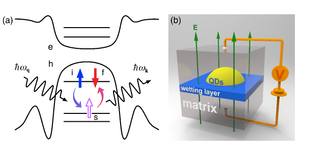
To calculate , we use the atomistic EPM to obtain high-quality hole energy levels and wave functions. Wei et al. (2012) We simulate a lens-shaped In1-xGaxAs/GaAs QDs embedded in a cubic GaAs matrix, containing 606060 GaAs 8-atom unit cells, as illustrated in the Fig. 1(b). The dot is grown along the [001] direction, on the top of a monolayer wetting layer. We first obtain optimized atomic positions (-th atom at the site ) by minimizing the total strain energy of the system (matrix+QDs) via valence force field (VFF) method. Keating (1966) The hole energy levels and wave functions are obtained by solving the following Schrödinger equation,
| (3) |
where is the total screened electron-ion potential, including the superposition of all atomistic pseudopotentials and the non-local spin-orbit potential . Wei et al. (2012) This method naturally includes the Rashba and Dresselhaus SOC in a “first-principles” manner. is the external potential due to the applied electric field, along the growth direction [see Fig. 1(b)]. 0 (0) corresponds to that the electric field points to the [001] ([00]) direction. We also applied an extremely small magnetic filed ( mT) along the growth direction to split the spin-up and spin-down states, where is the Pauli matrix and =2 is the Lande factor. The spin-up and spin-down energy difference caused by the magnetic field is negligible ( eV).
The Schrödinger equation is solved by the linear combination of bulk bands (LCBB) method. Wang and Zunger (1999) We use eight bands (including spin) for the hole in the calculation, which takes both the inter-valence-band coupling and the valence-conduction band coupling into account. A 6616 k-mesh converges the energy and wave functions very well. Wei et al. (2012); Williamson, Wang, and Zunger (2000) Due to the SOC, the wave functions are spin mixed, i.e. . We regard as a spin up (down) state if (). To calculate , we sum over 40 intermediate states (including spin), which converges the results within 0.1 ms. Wei et al. (2012)
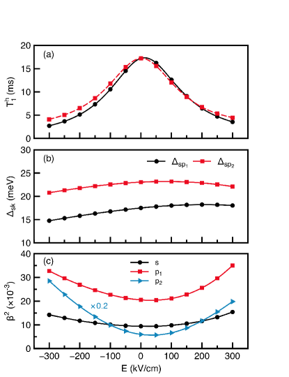
Figure 2(a) depicts the hole relaxation time (black solid line) at 4.2 K as a function of electric field () for a pure InAs/GaAs QDs with base diameter =20 nm and height =1.5 nm. We apply the electric field between and kV/cm, where the hole can still be trapped in the QDs. When no electric filed is applied (), we find the hole spin relaxation time =17.2 ms. For , decreases rapidly with the increasing . At kV/cm, decreases to 3.5 ms. For , with the increasing of , decreases to 2.7 ms at kV/cm. The short spin decay time may be useful in some cases, for example, fast spin initialization. The longest is approximately 17.4 ms at =17.2 kV/cm.
As discussed in our previous work, Wei et al. (2012) is determined by two factors: one is the energy difference between the lowest level () and the intermediate levels (). In this case, smaller can fasten the relaxation process. The other is minor spin component , which reflects the spin-up and spin-down mixture due to SOC. And in this case, lager leads to a smaller . We find that the electric field can tune the energy spacing between the and and level by approximately 24 meV, as shown in Fig. 2(b). Figure 2(c) shows the of the (black line), (red line) and (blue line) states as functions of . We find that the electric field can significantly change the spin mixture of the wave functions, due to the change of SOC by electric field. To determine the main mechanism that causes the change of , we artificially fix the hole energy levels at different applied electric fields to the ones at =0 kV/cm and recalculate . The results are shown in Fig. 2(a) in the dashed red line, which are rather close to the results using the electric field dependent energy levels. This clearly suggests that spin mixture tuned by electric field plays a major rule in tuning .
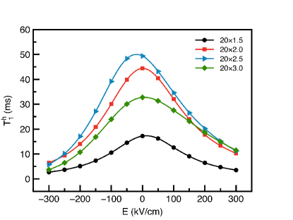
We further calculate at 4.2 K for QDs of different geometries. Figure 3 depicts as a function of in pure lens-shaped InAs/GaAs QDs with fixed base diameter =20 nm whereas the dot hight varies from 1.5 nm to 3.0 nm. For all QDs, the hole spin relaxation times are tuned by electric field in a very similar way. The spin relaxation time tends to decrease with . However, for the flat QDs, the tuning of by electric field is rather symmetric, whereas for taller dots the tuning becomes more asymmetric, because the geometry of dots themselves become more asymmetric. In all cases, the hole spin relaxation time can be tuned by more than one order of magnitude. For example, in the 20 nm3.0 nm QDs.
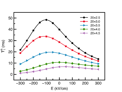
We find similar results for alloy In0.8Ga0.2As/GaAs QDs. We calculate for the dots with base diameter =20 nm, and the dot height varying from 2.5 nm to 4.5 nm. The results are shown in Fig. 4. Remarkably, the hole spin relaxation time can be significantly prolonged by the electric field in the alloy dots. Take the 20 nm2.5 nm QDs (black line in Fig. 4) as an example, first increases with the negative electric field and reaches to a maximum value 48 ms at about kV/cm. It starts to decrease when the electric field further increases. When a positive electric field is applied, decreases monotonically. The other dots show similar behaviors. However, with the increasing of the dot height, the which has the longest generally shifts to the more positive direction, as shown in Fig. 4.
To conclude, we have investigated the tuning of hole spin relaxation in single self-assembled In1-xGaxAs/GaAs QDs by electric field using an atomistic empirical pseudopotential method. We find that the electric filed can significantly increase or decrease the hole spin relaxation time in QDs, which provides an effective way to tune the hole spin relaxation time that may be useful for future device applications.
LH acknowledges support from the Chinese National Fundamental Research Program 2011CB921200 and National Natural Science Funds for Distinguished Young Scholars.
References
- Meier and Zakharchenya (1984) F. Meier and B. P. Zakharchenya, eds., Optical Orientation, Modern Problems in Condensed Matter Sciences, Vol. 8 (North-Holland, Amsterdam, 1984).
- Woods, Reinecke, and Lyanda-Geller (2002) L. M. Woods, T. L. Reinecke, and Y. Lyanda-Geller, Phys. Rev. B 66, 161318 (2002).
- Loss and DiVincenzo (1998) D. Loss and D. P. DiVincenzo, Phys. Rev. A 57, 120 (1998).
- Kane (1998) B. E. Kane, Nature 393, 133 (1998).
- Kroutvar et al. (2004) M. Kroutvar, Y. Ducommun, D. Heiss, M. Bichler, D. Schuh, G. Abstreiter, and J. J. Finley, Nature (London) 432, 81 (2004).
- Braun et al. (2005) P.-F. Braun, X. Marie, L. Lombez, B. Urbaszek, T. Amand, P. Renucci, V. K. Kalevich, K. V. Kavokin, O. Krebs, P. Voisin, and Y. Masumoto, Phys. Rev. Lett. 94, 116601 (2005).
- Heiss et al. (2007) D. Heiss, S. Schaeck, H. Huebl, M. Bichler, G. Abstreiter, J. J. Finley, D. V. Bulaev, and D. Loss, Phys. Rev. B 76, 241306(R) (2007).
- Gerardot et al. (2008) B. D. Gerardot, D. Brunner, P. A. Dalgarno, P. Öhberg, S. Seidl, M. Kroner, K. Karrai, N. G. Stoltz, P. M. Petroff, and R. J. Warburton, Nature (London) 451, 441 (2008).
- Eble et al. (2009) B. Eble, C. Testelin, P. Desfonds, F. Bernardot, A. Balocchi, T. Amand, A. Miard, A. Lemaître, X. Marie, and M. Chamarro, Phys. Rev. Lett. 102, 146601 (2009).
- Cheng, Wu, and Lü (2004) J. L. Cheng, M. W. Wu, and C. Lü, Phys. Rev. B 69, 115318 (2004).
- Trif, Simon, and Loss (2009) M. Trif, P. Simon, and D. Loss, Phys. Rev. Lett. 103, 106601 (2009).
- Wei et al. (2012) H. Wei, M. Gong, G.-C. Guo, and L. He, Phys. Rev. B 85, 045317 (2012).
- Warburton (2013) R. J. Warburton, Nature Mater. 12, 483 (2013).
- Bulaev and Loss (2005) D. V. Bulaev and D. Loss, Phys. Rev. Lett. 95, 076805 (2005).
- Dresselhaus (1955) G. Dresselhaus, Phys. Rev. 100, 580 (1955).
- Bychkov and Rashba (1984) Y. A. Bychkov and E. I. Rashba, J. Phys. C: Solid State Phys. 17, 6039 (1984).
- Balocchi et al. (2011) A. Balocchi, Q. H. Duong, P. Renucci, B. L. Liu, C. Fontaine, T. Amand, D. Lagarde, and X. Marie, Phys. Rev. Lett. 107, 136604 (2011).
- Kanai et al. (2011) Y. Kanai, R. S. Deacon, S. Takahashi, A. Oiwa, K. Yoshida, K. Shibata, K. Hirakawa, Y. Tokura, and S. Tarucha, Nature Nanotechnol. 6, 511 (2011).
- Prabhakar, Melnik, and Bonilla (2012) S. Prabhakar, R. V. N. Melnik, and L. L. Bonilla, Appl. Phys. Lett. 100, 023108 (2012).
- Prabhakar, Melnik, and Bonilla (2013) S. Prabhakar, R. Melnik, and L. L. Bonilla, Phys. Rev. B 87, 235202 (2013).
- Williamson, Wang, and Zunger (2000) A. J. Williamson, L.-W. Wang, and A. Zunger, Phys. Rev. B 62, 12963 (2000).
- Fras et al. (2012) F. Fras, B. Eble, P. Desfonds, F. Bernardot, C. Testelin, M. Chamarro, A. Miard, and A. Lemaître, Phys. Rev. B 86, 045306 (2012).
- Keating (1966) P. N. Keating, Phys. Rev. 145, 637 (1966).
- Wang and Zunger (1999) L.-W. Wang and A. Zunger, Phys. Rev. B 59, 15806 (1999).