Coexistence of trapped and free excess electrons in SrTiO3
Abstract
The question whether excess electrons in SrTiO3 form free or trapped carriers is a crucial aspect for the electronic properties of this important material. This fundamental ambiguity prevents a consistent interpretation of the puzzling experimental situation, where results support one or the other scenario depending on the type of experiment that is conducted. Using density functional theory with an on-site Coulomb interaction U, we show that excess electrons form small polarons if the density of electronic carriers is higher than . Below this value, the electrons stay delocalized or become large polarons. For oxygen-deficient SrTiO3, small polarons confined to Ti3+ sites are immobile at low temperature but can be thermally activated into a conductive state, which explains the metal-insulator transition observed experimentally.
pacs:
71.38.-k, 71.55.-i, 61.72.-y, 71.15.PdI INTRODUCTION
Strontium titanate is a key material in the emerging field of oxide electronics. It exhibits many attractive properties such as superconductivity Schooley , ferromagnetism Rice ; Moetakef , high thermoelectric coefficients Ohta , blue and green light emission Kan , and can accomodate a two dimensional electron gas Meevasana ; Wang14 . All these phenomena arise when a small number of electrons are introduced into the lattice. The characteristics and mobility of excess electrons is strongly determined by their interaction with the lattice through electron-phonon coupling. One of the manifestations of the electron-phonon interaction is the formation of a polaron, a quasiparticle formed by the excess electron and the structural deformations it induces Frohlich ; Devbook . Depending on the spatial extent of the polaronic wavefunction and associated structural distortions two types of polarons can be identified: in the small-polaron model the range of the distortion is of the order of the lattice constant, whereas in the large polaron the wavefunction spreads over several lattice sites and exhibits a more free-carrier-like behavior. Large polarons show a mobility inversely proportional to the number of longitudinal optical phonons. In contrast, small polarons form highly localized in-gap states and can hop to adjacent lattice sites when thermally activated Dev2000 .
Experimental information on the role of polarons in SrTiO3 is abundant, yet controversial Mazin ; Devreese ; Chang2010 ; Kohmoto ; Yamada2010 ; Liu ; Lee2011 ; Yamada ; Ishida ; Fujimori2 ; Higuchi ; Angelo ; Fujimori ; LeeM2011 . The key question is whether it is a large or a small polaron that is formed. Excess electrons introduced by doping or by oxygen defects have been identified as large polarons in transport measurements and optical spectroscopies Mazin ; Devreese . The validity of this picture is supported by recent angle-resolved photoemission spectroscopy data Chang2010 . Pump-probe spectroscopy in lightly photoexcited SrTiO3 suggested that itinerant electron polarons are the origin of diffusive lattice distortions Kohmoto . However, the large-polaron model cannot explain the in-gap bulk states in the conductive phase revealed in photoemission spectroscopy Fujimori ; Fujimori2 ; Higuchi ; Angelo . Instead, these highly localized states are attributable to small polarons trapped in bulk sites. This interpretation is reinforced by the recent observation that photoexcited electrons relax into self-trapped polaron states Yamada ; Kohmoto . Electron trapping has been also invoked to explain the metal-insulator transition (MIT) in SrTiO3-δ thin films Liu and single crystals Lee2011 . To complicate the situation even further, there are indications that excess electrons localized in trapped states can coexists with free carriers Devreese ; Ishida ; Yamada2010 ; LeeM2011 . No coherent picture can explain all these experiments so far; this has sparked an animated debate and poses a serious challenge to theory.
Computational studies provide additional insights. Based on density functional theory (DFT)+U, hybrid DFT and model Hamiltonians, it was suggested that the two additional electrons donated by a single oxygen vacancy VO induce one singly-occupied in-gap state mostly localized at the Ti atoms near the VO, and one state delocalized in the conduction band Hou ; Mitra ; Choi ; El-Mellouhi ; Lin ; Janotti14 . This conclusion successfully clarifies transport and optical properties in reduced SrTiO3, but is inconsistent with the observed VO-induced MIT Liu , because the predicted free carriers would be mobile even at low temperature.
The present study aims to provide a unified and coherent explanation of the role of excess electrons in SrTiO3. In particular it investigates the conditions under which localized and free-electron-like states can form, coexist and propagate. We show that a small-polaron regime is established if the carrier density is higher than a critical value, both in the low-temperature antiferrodistortive (AFD) and in the cubic structure. Below this critical density, the excess electrons will be delocalized or form large polarons, leading to a metallic solution without in-gap states, in nice agreement with experiment. Moreover, we provide theoretical evidence that the two excess electrons donated by VO form two self-trapped electrons, which become mobile if thermally activated, thus supporting the temperature-driven MIT observed in reduced SrTiO3 Liu .
II METHODS
For our calculations we adopted spin-polarized DFT+U within the gradient-corrected Perdew-Burke-Ernzerhof (PBE) functional PBE using the VASP VASP . An on-site was applied to the states of Ti. The value of the Coulomb and exchange parameters and was computed fully ab initio within the constrained Random Phase Approximation cRPA . To this aim the Kohn Sham orbitals were projected on to maximally localized Wannier functions Marzari1997 using the Wannier90 code. Franchini2012 ; Mostofi2008 For the construction of the correlated subspace we have followed the hybrid ”d-dp Hamiltonian”-like approach suggested by Vaugier and coworkersVaugier , where the Wannier functions are generated for the metal and oxygen orbitals, and only the bands are removed for the calculation of the effective interactions. Following this procedure we obtained eV and eV, and set eV, which is in line with previous DFT+U studies of polarons in SrTiO3 Hou ; Choi .
We considered both the cubic and the low-temperature (below 110 K) tetragonal AFD phase of SrTiO3 and at the optimized lattice constants (acubic = 3.948 Å, aAFD = 3.937 Å, c/aAFD=1.0055). Adopting these lattice constants the optmized rotation of the octahedra around the axis in the AFD phase is about 6∘, in agreement with previous DFT-based calculations wahl . To mimic substitutional (Ti/Nb) doping and VOs we employed an supercell (SC) with , 4, 5, and 6 (up to 1080 atoms). For each SC all atomic positions were relaxed until the residual force on each atom was less than 0.02 eV/Å.
The polaron formation energy is defined as the energy difference between the delocalized, free electron solution and the localized polaron solution. Both these solutions can be modeled by DFT. The delocalized solution can be achieved within a standard non spin-polarized calculation. To model the small polaron solution different schemes can be adopted as recently discussed in Ref. Shibuya, . We have followed the following strategy, proposed by Deskins et al. Deskins :
-
1.
First, we have chosen the specific Ti sites at which we aim to stabilize a polaron and substituted that distinct Ti with a V atom and let the structure relax within a spin-polarized set-up. In this way we break the symmetry and allow an expansion of the oxygen octahedron around the V.
-
2.
Second, we placed back the Ti atom in the V position and let the structure relax within a spin-polarized set-up by initializing a local magnetic moment equal to one in this specific Ti site.
For particularly complicated polaronic configurations (i.e. difficult to converge) we have added an intermediate step in which we have performed a step-2 calculation using a larger value of the on-site at the Ti site at which we wanted to form the polaron. In this way we could more easily attract the excess electron to that specific Ti site. In a subsequent run, we recovered the usual value of and let the system relax. This procedure was repeated for several polaronic configurations and the corresponding total energies were compared to the total energy of the delocalized solution.
We verified that the results were converged with respect to the energy cutoff (400 eV) and number of k-points (121212 with respect to the primitive cubic cell). Molecular dynamics (MD) simulations of small polaron hopping in SrTiO3-δ with were performed at simulated temperatures ranging from 700 K to 1000 K for 5 ps with a time step of 1 fs. The MD are also performed within the DFT+U framework. We expect that the inclusion of the inter-site effective interaction Campo , which have never been employed to describe the dynamics of polarons, could improve further the agreement with experiments. For SrTiO3 our cRPA procedure delivers =1.7 eV.
III RESULTS AND DISCUSSION
In this section we present and discuss the results obtained for the Nb-doping and oxygen vacancies calculations.
III.1 Nb-doping
The substitution of one Ti with one Nb in a cubic SC, corresponding to an electron density of cm-3, establishes a non-conducting state with a rather sharp peak at about 0.80 eV below the conduction band minimum (CBM, see Fig. 1), in line with the experimental values of 1.0 - 1.5 eV Fujimori ; Fujimori2 ; Higuchi ; Angelo ; Yamada . From an analysis of the charge character we infer that this state locates almost completely on one distinct Ti atom, and gives rise to a configuration with a magnetic moment of about 0.9 . Consequentially, the Ti atom is reduced to Ti3+. The electron trapping is accompanied by local structural deformations manifested by the elongation of all Ti-O bond lengths within the Ti3+O6 octahedron by about 0.05 Å as shown in Fig. 2. This is the typical fingerprint of a small polaron.
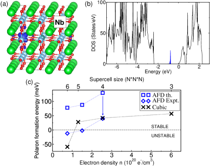

The stability of the small polaron is determined by the competition between the structural energy required to distort the lattice , and the electronic energy gained by localizing the excess electron at a specific Ti site . We found a positive polaron formation energy of 57 meV for the smallest cubic supercell, which means that the small polaron is stable.
A key parameter, which has been largely overlooked in previous theoretical studies, is the role of the carrier density. To clarify this issue, we have performed analogous calculations using larger SCs, thus varying the doping concentration from =3.7% (N=3, =61020 cm-3) to =0.5 % (N=6, =71019 cm-3). We find that the polaron formation energy strongly depends on the carrier density, see Fig. 1(c). For the smallest Nb-doping SC (N=3) we have also studied the effects of the change of the volume due to Nb-doping. We found that the lattice constant expands from a = 3.945 Å to 3.993 Å and the polaron formation energy increases up to 140 meV. Following Vegard’s law the volume expansion and its effect on the polaron formation energy becomes negligible for larger supercell for which the Nb concentration is very small.
Within the low- AFD setup the small-polaron formation energy substantially increases for all values of the carrier density [Fig. 1(c), square symbols] using the optimized DFT+U volume. This is explained by the larger Ti-O bond lengths in the low-temperature AFD structure as well as its higher structural flexibility compared to the cubic phase; both make the small polaron more favorable. DFT-based calculations strongly overestimate the AFD distortions however Uchida ; wahl . Therefore, more realistic values for the AFD phase will be closer to those for the cubic phase. Indeed, by performing AFD calculations fro the N=4 SC at the experimental lattice constants the polaron formation energy is reduced by about 90 meV as indicated in Fig. 1(c).
The stability of the small polaron decreases as the carrier density decreases. For N6 it eventually becomes negative, indicating that the excess electron is prone to delocalization over the entire SC, or to create a large polaron.
This localized-to-delocalized transition is explained by analyzing the energy balance involved in the electron trapping process. The small polaron is stable when the electronic energy gain is larger than the structural energy loss . does not depend on the carrier density, but may depend on the presence of the dopant (Nb). Indeed, we found that self-trapping in a perfect (defect free) lattice is unstable. An increased Ti3+-O bond length for the O atom binding to a neighboring Nb dopant indicate that the dopant provides the crystal with the structural flexibility (i.e., small ) needed to accommodate an electron in a locally distorted Ti3+ site close to the Nb impurity. This argument applies to other types of structural deformations such as surface reconstructions and steps, which are found to favour small polaron formation. Setvin1 ; Setvin2
We have verified that the stability of a polaron decreases by increasing the Ti3+-Nb distance and that the small polaron solution becomes unstable for Ti sites far from the Nb dopant. This indicates that dopants are necessary to activate electron trapping: without the dopant, excess electrons prefer to behave like free carriers. On the other hand, depends on the carrier density through electronic correlation. The repulsion among the Nb-induced extra electrons is expected to get weaker at low concentration, attenuating the attraction between the excess electrons and the positively charge Nb center. Although small, this effect may become relevant for cases in which the polaron energy is very small ( ).
To ascertain the role of on the polaron formation energy we have also performed some calculations for different values of ( 1 eV with respect to the cRPA value). In agreement with previous studies we found that the polaron formation energy scales almost linearly with Setvin1 : for =4 the polaron formation energy becomes negative for (cubic) and (AFD).
Thus, in the limit of low concentration, becomes larger than , the polaron solution unstable and the excess electron begin to delocalize. It is extremely challenging to accurately describe delocalized large polarons from first principles. By incorporating many-body effects in Frhlich’s large polaron Hamiltonian Frohlich , Devreese et al. Devreese have computed the low-T optical conductivity of Nb-doped SrTiO3 with large polarons for different dopant concentrations and found the best agreement with experiment at low carrier concentration ( cm-3), in good agreement with the regime where we predict small polarons to be unstable [Fig. 1(c)]. Inserting the characteristic electron-phonon coupling constant Devreese and the characteristic longitudinal optical phonon frequency Servoin in the Frhlich’s model, we obtain a spatial extension of the large polaron in SrTiO3 of 9-19 Å, i.e., 3-5 unit cells.
Our findings resolve puzzling and apparently conflicting results observed in Nb-doped SrTiO3. First, the unusually narrow Drude feature for carrier concentrations between 0.1% and 2% per unit cell Mazin can be understood by the large-polaron model, in line with our calculations for a small carrier density. Second, the in-gap states detected by photoemission spectroscopy in moderately doped samples (1% 5%), suggest a semiconducting regime Higuchi , in excellent agreement with our small polaron picture. At the transition from localized to free-carrier behavior, where the formation energy of small polarons is very small, the thermal excitation is high enough to surmount it, resulting in a situation where the trapped and mobile electrons can coexist in the system. This picture can explain the existence of in-gap states in the conductive phase measured by photoemission spectroscopy studies Fujimori ; Fujimori2 ; Higuchi ; Angelo , and can be rationalized in terms of an inhomogeneous distribution of impurities or defects as suggested in experimental works Szot ; Muller .
III.2 Oxygen vacancies
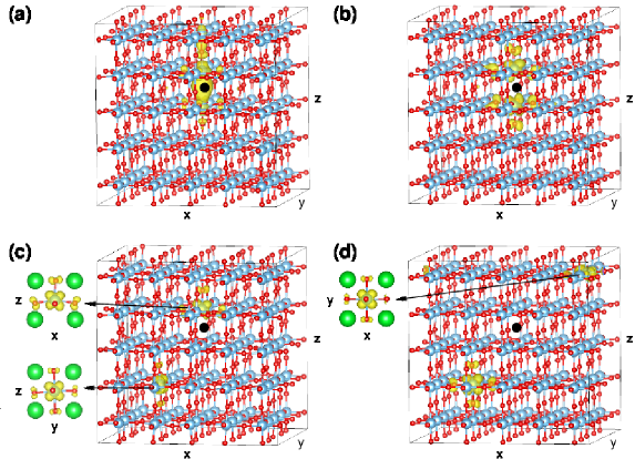
To analyze the reduced sample we employed a cubic 555 SC with one VO, resulting in two excess electrons per SC. Previous computational analyses suggest that one VO induces a singly-occupied in-gap state, and donates one free carrier to the conduction band Hou ; Mitra ; Choi ; El-Mellouhi ; Janotti14 . We label this mixed localized/free-carrier polaron configuration P1. The corresponding charge density isosurface is plotted in Fig. 3.
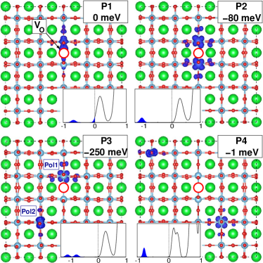
Based on a systematic search of several configurations we have identified three more stable polaron patterns (P2, P3, and P4, Fig. 3). All of them have an insulating density of states with polaron peaks between 0.8 and 1.1 eV below the CBM. The polaron topologies of the various configurations differ in distance between the polaron and the VO, as depicted in Fig. 3 and 4. The most stable configuration is P3, with one polaron anchored near VO and the second one localized in a Ti3+ site 8 Å away from VO. P3 is more favorable than P1 by 250 meV. Different from previous calculations, all our additional polaron states display a t2g distribution instead of eg (d).
From a structural point of view, removal of a single O atom makes the nearest-neighbor (NN) Ti (two) and Sr (four) atoms move away from the vacant site, while the eight NN oxygen atoms relax toward the vacancy site, as already noted in Refs. Buban ; Carrasco . In addition, the TiO6 octahedra near VO are subjected to AFD-like rotations Choi ; Uchida (see Fig. 3). These structural changes occur irrespective of the polaronic configuration. At the polarons (Ti3+), the lattice relaxes similarly to the Nb-doped case. We emphasize that a proper treatment of local structural relaxations within a large unit cell is of primary importance for achieving a localized solution.
Thus, a key element of our results is that the excess electrons induced by VO do not form a mixed state of free and trapped carriers, as suggested by previous theoretical studies, but rather a ”double polaron” with two trapped electrons in distinct Ti3+ sites.
Now, how can this scenario explain the temperature-driven MIT observed in SrTiO3-δ with homogeneously distributed VOs? To answer this question we have conducted MD runs to probe the possibility to thermally activate the hopping mobility of the VO-induced small polarons. We have monitored the position of the two polarons as a function of time for different temperatures, each time starting from the ground state configuration P3.
From the K and K results in Fig. 5 we infer that one of the polarons stays bound to the VO forming a complex Janotti . This polaron gives rise to an optical absorption peak at about 1.1 eV below the CBM (see P3 DOS in Fig. 3), whereas the second one can easily hop to other sites, enabling electrical conductivity. This polaron forms a peak at 0.8 eV below the CBM (see P3 DOS in Fig. 3). The oxygen vacancy does not undergo any diffusion during the MD run, in line with the reported large migration barrier for oxygen diffusion (0.98 eV). Yamaji
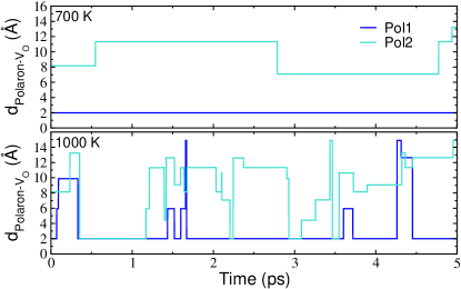
The mobility increases with increasing temperature. At K we register 36 polaron migrations in 5 ps. MD finds several other polaron topologies, with many minima close together on the potential energy landscape. The P3 pattern remains the most favorable one ( 65 % of the time), followed by P2 ( 20 %) and P4 ( 10 %). Importantly, MD never leads to a mixed localized/free-carrier P1-like configuration, although a degree of delocalization naturally emerges in the transition state from one minimum to the next one. The various minima could be populated at finite temperatures. Employing a simple Arrhenius equation, an activation energy of approximately 150 meV is estimated.note
In order to assess the minimum energy barrier for small polaron hopping, we have investigated an abbreviated version of this process through the climbing image nudged-elastic band method Henkelman , using a 3 3 3 SC. We obtained migration barriers of 204 meV, 177 meV and 176 meV for small polaron hopping along the [100], [110] and [111] directions, respectively, in agreement with the value derived from the MD runs.
Our MD results provide a sound interpretation of the temperature-driven MIT in reduced SrTiO3: at high temperature the electrons exhibit hopping mobility, but once the temperature decreases, they will get trapped in polaron levels giving rise to a semiconducting regimeLiu .
Finally, we would like to mention that we did not find any significant energy difference between the ferromagnetic and antiferromagentic arrangement of the trapped electrons. Hence, the hypothesis that VOs are the cause of the observed ferromagnetism in SrTiO3 Liu2 deserves further investigation.
IV Summary
In summary, DFT+U calculations in conjunction with molecular dynamics simulations provide insights into the behavior of excess electrons in SrTiO3. We predict a carrier-density dependent transition between a semiconducting behavior with in-gap polaron states and a conductive regime. Our findings reconcile conflicting experimental data and elucidates the fundamental physics behind. Our account of the oxygen defective SrTiO3 at sufficiently high carrier concentration revisits previous theoretical results and leads to a unified and consistent explanation of the measured data: at low temperature the excess electrons are confined in Ti3+ sites and become mobile when thermally activated.
V ACKNOWLEDGMENTS
This work was supported by the ERC Advanced Research Grant ‘OxideSurfaces’, by the Austrian Science Fund (FWF) project F45, and by the National Natural Science Foundation of China (Grant No. 21201148 and 21303156). X.H. thanks Zhicheng Zhong for helpful discussions.
References
- (1) J.F. Schooley, W.R. Hosler and M.L. Cohen, Phys. Rev. Lett. 12, 474 (1964).
- (2) W. D. Rice, P. Ambwani, M. Bombeck, J. D. Thompson, G. Haugstad, C. Leighton & S. A. Crooker, Nat. Mater. 13, 481 (2014).
- (3) Pouya Moetakef, James R. Williams, Daniel G. Ouellette, Adam P. Kajdos, David Goldhaber-Gordon, S. J. Allen, and Susanne Stemmer, Phys. Rev. X 2, 021014 (2012).
- (4) H. Ohta et al., Nat. Mater. 6, 129 (2007).
- (5) D. Kan et al., Nat. Mater. 4, 816 (2005).
- (6) W. Meevasana, P. D. C. King, R. H. He, S-K. Mo, M. Hashimoto, A. Tamai, P. Songsiriritthigul, F. Baumberger & Z-X. Shen, Nat. Mater. 10, 114 (2011).
- (7) Z. Wang, Z. Zhong, X. Hao, S. Gerhold, B. Stoeger, M. Schmid, J. Sanchez-Barriga, A. Varykhalov, C. Franchini, K Held, and U. Diebold, Proc. Nat. Acad. Sci. 111, 3933 (2014).
- (8) H. Frhlich, Adv. Phys. 3, 325 (1954).
- (9) Alexandre S. Alexandrov and Jozef T. Devreese, 2010, Devreese Advances in Polaron Physics, Springer Series in Solid-State Sciences Vol 159 (Springer-Verlag, New York).
- (10) J.T. Devreese, Encyclopedia of Applied Physics Vol. 14, 383 (Wiley-VCH Publishers, Inc., 1996)
- (11) J. L. M. van Mechelen, D. van der Marel, C. Grimaldi, A. B. Kuzmenko, N. P. Armitage, N. Reyren, H. Hagemann, and I. I. Mazin, Phys. Rev. Lett. 100, 226403 (2008).
- (12) J. T. Devreese, S. N. Klimin, J. L. M. van Mechelen, and D. van der Marel Phys. Rev. B 81, 125119 (2010).
- (13) Young Jun Chang, Aaron Bostwick, Yong Su Kim, Karsten Horn, and Eli Rotenberg, Phys. Rev. B 81, 235109 (2010).
- (14) T. Kohmoto, D. Ikeda, X. Liang, and T. Moriyasu, Phys. Rev. B 87, 214301 (2013).
- (15) Y. Yamada and Y. Kanemitsu, Phys. Rev. B 82, 121103(R) (2010).
- (16) Z.Q. Liu et al., Phys. Rev. Lett. 107, 146802 (2011).
- (17) Yeonbae Lee, Colin Clement, Jack Hellerstedt, Joseph Kinney, Laura Kinnischtzke, Xiang Leng, S. D. Snyder, and A. M. Goldman, Phys. Rev. Lett. 106, 136809 (2011).
- (18) Yasuhiro Yamada, Hiroki K. Sato, Yasuyuki Hikita, Harold Y. Hwang, and Yoshihiko Kanemitsu, Phys. Rev. Lett. 111, 047403 (2013).
- (19) Yukiaki Ishida, Ritsuko Eguchi, Masaharu Matsunami, Koji Horiba, Munetaka Taguchi, Ashish Chainani, Yasunori Senba, Haruhiko Ohashi, Hiromichi Ohta, and Shik Shin, Phys. Rev. Lett. 100, 056401 (2008).
- (20) A. Fujimori et al., Phys. Rev. B 46, 9841 (1992).
- (21) T. Higuchi, T. Tsukamoto, K. Kobayashi, Y. Ishiwata, M. Fujisawa, T. Yokoya, S. Yamaguchi, and S. Shin, Phys. Rev. B 61, 12860 (2000).
- (22) M. D’Angelo, R. Yukawa, K. Ozawa, S. Yamamoto, T. Hirahara, S. Hasegawa, M. G. Silly, F. Sirotti, and I. Matsuda, Phys. Rev. Lett. 108, 116802 (2012).
- (23) A. Fujimori et al., J. Phys. Chem. Solids 57, 1379 (1996).
- (24) Menyoung Lee, J. R. Williams, Sipei Zhang, C. D. Frisbie, and D. Goldhaber-Gordon, Phys. Rev. Lett. 107, 256601 (2011).
- (25) Z. Hou and K. Terakura, J. Phys. Soc. Jpn. 79, 114704 (2010).
- (26) C. Mitra, C. Lin, J. Robertson, and Alexander A. Demkov, Phys. Rev. B 86, 155105 (2012).
- (27) Minseok Choi, Fumiyasu Oba, Yu Kumagai and Isao Tanaka, Adv. Mater. 25, 86 (2013).
- (28) Fedwa El-Mellouhi, Edward N. Brothers, Melissa J. Lucero and Gustavo E. Scuseria, J. Phys.:Condens. Matter 25, 135501 (2013).
- (29) C. Lin and A.A. Demkov, Phys. Rev. Lett. 111, 217601 (2013).
- (30) Anderson Janotti, Joel B. Varley, Minseok Choi, and Chris G. Van de Walle, Phys. Rev. B 90, 085202 (2014).
- (31) J.P. Perdew, K. Burke and M. Ernzerhof, Phys. Rev. Lett. 77, 3865 (1996).
- (32) G. Kresse and J. Hafner, Phys. Rev. B 48, 13115 (1993); G. Kresse and J. Furthmller, Comput. Mater. Sci. 6, 15 (1996).
- (33) F. Aryasetiawan, K. Karlsson, O. Jepsen, and U. Schönberger, Phys. Rev. B 74, 125106 (2006).
- (34) N. Marzari and D. Vanderbilt, Phys. Rev. B 56, 12847 (1997).
- (35) C. Franchini, R. Kováik, M. Marsman, S. Sathyanarayana Murthy,J. He, C. Ederer, and G. Kresse, J. Phys.: Condens. Matter 24, 235602 (2012).
- (36) A. A. Mostofi, J. R. Yates, Y.-S. Lee, I. Souza, D. Vanderbilt, and N. Marzari, Comput. Phys. Commun. 178, 685 (2008).
- (37) Loïg Vaugier, Hong Jiang, and Silke Biermann, Phys. Rev. B 86, 165105 (2012).
- (38) Roman Wahl, Doris Vogtenhuber, and Georg Kresse, Phys. Rev. B 78, 104116 (2008).
- (39) Taizo Shibuya, Kenji Yasuoka, Susanne Mirbt and Biplab Sanyal, J. Phys.: Condens. Matter 24, 435504 (2012).
- (40) N. Aaron Deskins, Roger Rousseau, and Michel Dupuis, J. Phys. Chem. C 115, 7562 (2011).
- (41) Vivaldo Leiria Campo Jr. and Matteo Cococcioni, J. Phys.: Condens. Matter 22, 055602 (2010).
- (42) G. Makov and M. C. Payne, Phys. Rev. B 51, 4014 (1995).
- (43) K. Uchida, S. Tsuneyuki, T. Schimizu, Phys. Rev. B 68, 174107 (2003).
- (44) Martin Setvin, Cesare Franchini, Xianfeng Hao, Michael Schmid, Anderson Janotti, Merzuk Kaltak, Chris G. Van de Walle, Georg Kresse, and Ulrike Diebold, Phys. Rev. Lett. 113, 086402 (2014).
- (45) Martin Setvin, Xianfeng Hao, Benjamin Daniel, Jiri Pavelec, Zbynek Novotny, Gareth Parkinson, Michael Schmid, Georg Kresse, Cesare Franchini, and Ulrike Diebold Angew. Chem., Int. Ed. 53, 4714 (2014).
- (46) J.L. Servoin, Y. Luspin, and F. Gervais, Phys. Rev. B 22, 5501 (1980).
- (47) K. Szot, W. Speier, R. Carius, U. Zastrow, and W. Beyer, Phys. Rev. Lett. 88, 075508 (2002).
- (48) David A. Muller, Naoyuki Nakagawa, Akira Ohtomo, John L. Grazul & Harold Y. Hwang Nature (London) 430, 657 (2004).
- (49) James P. Buban, Hakim Iddir, and Serdar Öǧüt, Phys. Rev. B 69, 180102 (2004).
- (50) J. Carrasco, F. Illas, N. Lopez, E. A. Kotomin, Yu. F. Zhukovskii, R. A. Evarestov, Yu. A. Mastrikov, S. Piskunov, and J. Maier, Phys. Rev. B 73, 064106 (2006).
- (51) A. Janotti, C. Franchini, J. B. Varley, G. Kresse, and C. G. Van de Walle, Phys. Status Solidi 7, 199 (2013).
- (52) In Ref. Liu , an Arrhenius plot of the carrier density is interpreted as an activation energy of 25 meV, but this is for temperatures in the ‘metallic’ conductance regime. In the dopant model suggested there, charge carrier saturation would occur under these conditions; thus the interpretation of the Arrhenius plot is questionable.
- (53) A. Yamaji, J. Am. Ceram. Soc. 58, 152 (1975).
- (54) Graeme Henkelman, Blas P. Uberuaga and Hannes Jónsson, J. Chem. Phys. 113, 9901 (2000).
- (55) Z.Q. Liu et al., Phys. Rev. B 87, 220405(R) (2013).