Strong Purcell effect in anisotropic -near-zero metamaterials
Abstract
We theoretically demonstrate the strong Purcell effect in -near-zero ultra-anisotropic uniaxial metamaterials with elliptic isofrequency surface. Contrary to the hyperbolic metamaterials, the effect does not rely on the diverging density of states and evanescent waves. As a result, both the radiative decay rate and the far-field emission power are enhanced. The effect can be realized in the periodic layered metal-dielectric nanostructures with complex unit cell containing two different metallic layers.
pacs:
78.67.Pt, 42.88.+h, 42.70.QsEpsilon-near-zero materials, i.e. materials with small effective permittivity , are in the focus of active theoretical Basharin et al. (2013); Savoia et al. (2014) and experimental Liu et al. (2008); Vesseur et al. (2013); Maas et al. (2013) research being very promising for applications including, for example, guiding of light Edwards et al. (2008); Luo et al. (2012), phase front manipulation Alù et al. (2007), optical circuitry Engheta (2007), and photovoltaics Molesky et al. (2013). However, at the first glance they do not look beneficial for nanophotonic applications and enhancement of the light-matter coupling. Indeed, the Purcell factor in an isotropic medium with the dielectric constant is equal to and tends to zero for small Novotny and Hecht (2006). In this letter, we draw attention to the anisotropic uniaxial -near-zero medium, satisfying the condition
| (1) |
The Purcell factor for the emitter embedded in the uniaxial material and polarized perpendicular to the symmetry axis is equal to Poddubny et al. (2011)
| (2) |
In the isotropic regime Eq. (2) reduces to . However, in the strongly anisotropic limit (1) one can obtain very large values of the Purcell factor due to the divergence in the first term . The condition Eq. (1) can be realized when the longitudinal dielectric tensor component stays finite and the transverse one () becomes small. Alternatively, one can consider a situation when both and tend to zero with different rates, so that remains much larger than .
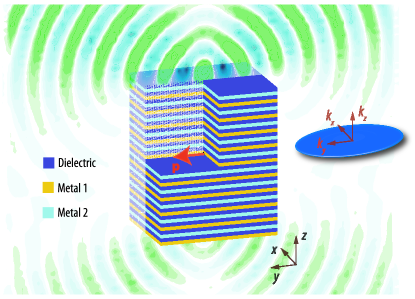
In the media satisfying Eq. (1) the isofrequency surface, i.e. the surface spanned by the wave vectors of transverse magnetic (TM) modes corresponding to the same frequency, has a shape of a strongly oblate ellipsoid (see the inset of Fig. 1). The condition (1) is realized at the elliptic side of the topological transition between elliptic and hyperbolic regimes Jacob and Shalaev (2011); Cortes et al. (2012); Drachev et al. (2013); Poddubny et al. (2013). While the hyperbolic regime, when , allows to realize strong Purcell effect as well, it is strongly qualitatively different from the considered case. Particularly, in the hyperbolic metamaterials the spontaneous emission is mostly due to the photon modes with large wave vectors, that lead to the diverging density of states but are evanescent outside the structure and can not be detected in the far field unless the structure surface is patterned to facilitate their outcoupling Lu et al. (2014). Hence, the transition from elliptic to the hyperbolic regime is accompanied by shortening of the emission lifetime and suppression of the observed far field emission intensity Tumkur et al. (2011); Kim et al. (2012). In the considered anisotropic elliptic case the density of states stays finite, no evanescent waves are involved, and, as a result, both the radiative decay rate and the far field emission power can be enhanced.
Now we proceed to the discussion of the origin of the strong Purcell effect and the realization of the anisotropic elliptic regime Eq. (1) in layered metal-dielectric metamaterials. The origin of the spontaneous emission enhancement can be most easily demonstrated by the Fermi Golden rule calculation:
| (3) |
Here, is the radiative decay rate, is the emission frequency for the two-level system, is the dipole matrix element, and is the electric field operator amplitude corresponding to the single quantum of radiation. The integration is performed over the wave vectors of emitted waves with the TE or TM polarization denoted by . Below we outline the calculation of the spontaneous emission rate; the general result valid both in elliptic and hyperbolic regimes and accounting for losses can be found in Ref. Poddubny et al. (2011). The electric field amplitude can be presented as
| (4) |
where the effective mode volume is determined from the quantization condition for the plane waves , is the normalization volume, and are the spherical coordinates of the wave vector . The effective mode volume
| (5) |
can be expressed via effective refractive index determining the TM modes dispersion ,
| (6) |
Substituting Eqs. (5),(6) into Eq. (3) and performing the integration over and we obtain the contribution of the TM modes to the radiative decay rate for the -polarized transition
| (7) |
Equation (7) has a divergency for . While this divergency takes place at the threshold of the hyperbolic regime the origin of the emission enhancement is quite different from the case of hyperbolic metamaterials, because the density of states stays finite. Particularly, in the ultra-anisotropic regime the spontaneous emission is dominated by the waves propagating at the grazing angles to the symmetry plane, :
| (8) |
where . The sharp strong maximum in Eq. (8) for is due to the diverging effective refractive index Eq. (6) which means vanishing effective mode volume Eq. (5). The small effective mode volume leads to the strong Purcell effect, similarly to the case of resonant cavities.
The final result for Purcell factor is obtained by including the contribution of the TE modes (determined by the effective index ) and normalizing to the free-space radiative decay rate . The expressions for and polarized emitters read
| (9) | ||||
| (10) |
It is the first term in Eq. (9) that presents the contribution of the TM waves to the spontaneous emission rate and can be arbitrary large in the ultra-anisotropic elliptic regime. The effect is present only for the emitters polarized in plane, cf. Eq. (9) and Eq. (10).
This is how we arrive to an idea such the regime can be realized in actual artificial media. The seemingly natural approach is to consider plasmonic multilayers Subramania et al. (2012); Orlov et al. (2014a) that are layered metal-dielectric structures formed by a periodic stack of metallic and dielectric layers. Conventional multilayers formed by the layers of two kinds described typically with the following permittivities Agranovich and Kravtsov (1985):
| (11) | |||
| (12) |
where the angular brackets denote the spatial averaging. Analyzing these equations we find that the condition Eq. (1) is realized at the frequency slightly above the transition frequency , corresponding to the transition between the elliptic and hyperbolic regimes
| (13) |
when turns to zero. The condition requires , i.e. the metallic layers should be thinner than the dielectric ones. Particularly, this means that the absolute value of is larger than at the frequency and the frequency is lower than the surface plasmon frequency determined from the condition . However, it turns out that in this case the corresponding isofrequency contour consists not only of the elliptic contour but possesses an additional hyperbolic branch due to the inherent strong spatial dispersion of the plasmonic multilayer Orlov et al. (2011). Dispersion diagram of the structure as a function of the normalized in-plane wave vector is shown in Fig. 2(a). The mode I has an elliptic dispersion, but it is spectrally overlapped with the mode II that is hyperbolic one. Hence, the effect of the mode I on the spontaneous emission is completely masked by the contribution of the mode II.
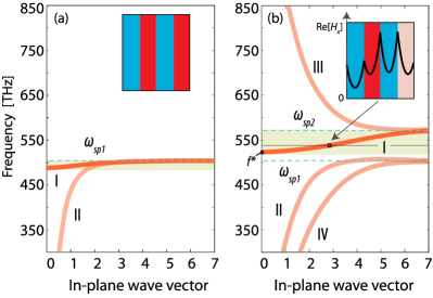
In order to obtain the isolated elliptic isofrequency contour we propose plasmonic multilayer structures having complex unit cell with bi-periodicity Orlov et al. (2014b). Particularly, we consider the system formed by four layers per period, two different metallic ones and two equal dielectric ones, as shown in Fig. 1. We choose the dielectric layers with the same permittivity of . The metallic layers are described by the Drude model: , with different plasma wavelengths = 250 nm and = 220 nm. All layers are chosen to have equal thickness of nm. Dispersion diagram for this case is presented in Fig. 2(b). The photonic band structure of the bi-periodic multilayer possesses four branches, contrary to two branches in the conventional plasmonic multilayer with simple unit cell [Fig. 2(a)].
Since the complex unit cell is formed by different metallic layers, two surface plasmon resonances can be distinguished in Fig. 2(b), positioned at the frequencies and . The mode I lies between these two frequencies being bounded from above by and from below by the threshold frequency . It is blue-shifted in comparison with the mode I of Fig. 2(a). At the same time, the mode II occupies the former region below . Thus, the mode I becomes spectrally isolated allowing us to realize the ultra-anisotropic elliptic regime. Particularly, its magnetic field keeps the same sign within the unit cell [inset of Fig. 2(b)]. Hence, this mode is still qualitatively described within the effective medium approximation by the period-averaged effective dielectric constant and remains elliptic [see Fig. 3(b)]. In the spectral range of mode I we expect strong radiative Purcell effect.
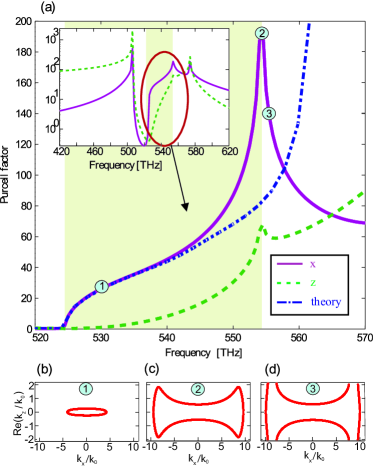
In order to demonstrate the effect, we have calculated the spectral dependence of the Purcell factor for the emitter placed in the middle of the dielectric layer inside the infinite periodic structure. We have applied the Green function technique for layered structures Tomaš and Lenac (1999). The result is shown in Fig. 3. The solid violet curve has been calculated for the emitter oriented along the layers, the green dashed curve corresponds to the perpendicular orientation. Figures 3(b)–(d) show the isofrequency contours for three particular frequencies. The frequency 530 THz corresponds to the main result of this work: in this case the isofrequency contour has strongly anisotropic elliptic shape, and the Purcell factor reaches the value of 25 (violet line). For frequencies lower than 530 THz the most part of the isofrequency contour lies within the range of free space propagating waves, , and hence the energy can be radiated in the far field [Fig. 1]. The increase of the Purcell factor in the elliptic regime is observed only for the emitter oriented parallel to the layers. Indeed, the elliptic regime is achieved in the frequency range 524 – 540 THz, when the Purcell effect for the transverse emitter’s orientation is quite weak (dashed green curve). Such polarization dependence of the Purcell factor is in perfect qualitative agreement with the effective medium prediction Eqs. (9),(10). The dash-dotted blue curve in panel (a) shows the effective medium result obtained using the values of and extracted by fitting the isofrequency contours. The function Eq. (9) has been multiplied by the factor 1.4, that can be interpreted as a local field correction to the effective medium model Poddubny et al. (2012). This semi-analytical expression well describes the numerically calculated frequency dependence of the Purcell factor [cf. violet and blue curves in Fig. 3(a) ].
Here, we have focused on the case of vanishing losses. While the Purcell enhancement due to the elliptic branch I is strongly suppressed for realistic losses, the effect can be further optimized by considering the metals with larger difference of the plasma frequencies. In the spectral range 540–554 THz the isofrequency contour evolves from an ellipsoid to the dumbbell, and, at frequencies larger than 554 THz it splits into two hyperbolic branches corresponding to mode III in Fig. 2. In these regimes the spontaneous emission is quite fast, but dominated by evanescent waves.
To summarize, we have demonstrated how the strong Purcell enhancement of both the spontaneous emission rate and the far-field emission power can be realized in the ultra-anisotropic uniaxial metamaterials where the transverse component of the dielectric tensor is positive but much smaller than the axial one. Our work shows that the possibilities to engineer the photon dispersion and the light-matter coupling in layered metal-dielectric nanostructures reach far beyond the established concepts of individual surface plasmon modes, hyperbolic metamaterials or isotropic -near-zero medium and are yet to be fully explored.
Acknowledgements.
The authors are grateful to I.V. Shadrivov and Yu. S. Kivshar for useful discussions. This work has been supported by the President of Russian Federation (Grant SP-2154.2012.1), the Government of Russian Federation (Grant 074-U01), and Russian Foundation for Basic Research (Project 14-02-31720). ANP acknowledges the support of the “Dynasty” foundation. The work of ASS (numerical simulations and investigating of the field distributions) has been funded by the Russian Science Foundation Grant No. 14-12-01227.References
- Basharin et al. (2013) A. A. Basharin, C. Mavidis, M. Kafesaki, E. N. Economou, and C. M. Soukoulis, Phys. Rev. B 87, 155130 (2013).
- Savoia et al. (2014) S. Savoia, G. Castaldi, V. Galdi, A. Alù, and N. Engheta, Phys. Rev. B 89, 085105 (2014).
- Liu et al. (2008) R. Liu, Q. Cheng, T. Hand, J. J. Mock, T. J. Cui, S. A. Cummer, and D. R. Smith, Phys. Rev. Lett. 100, 023903 (2008).
- Vesseur et al. (2013) E. J. R. Vesseur, T. Coenen, H. Caglayan, N. Engheta, and A. Polman, Phys. Rev. Lett. 110, 013902 (2013).
- Maas et al. (2013) R. Maas, J. Parsons, N. Engheta, and A. Polman, Nat. Phot. 7, 907–912 (2013).
- Edwards et al. (2008) B. Edwards, A. Alu, M. E. Young, M. Silveirinha, and N. Engheta, Phys. Rev. Lett. 100, 033903 (2008).
- Luo et al. (2012) J. Luo, P. Xu, H. Chen, B. Hou, L. Gao, and Y. Lai, Appl. Phys. Lett. 100, 221903 (2012).
- Alù et al. (2007) A. Alù, M. G. Silveirinha, A. Salandrino, and N. Engheta, Phys. Rev. B 75, 155410 (2007).
- Engheta (2007) N. Engheta, Science 317, 1698 (2007).
- Molesky et al. (2013) S. Molesky, C. J. Dewalt, and Z. Jacob, Opt. Expr. 21, A96 (2013).
- Novotny and Hecht (2006) L. Novotny and B. Hecht, Principles of Nano-Optics (Cambridge University Press, New York, 2006).
- Poddubny et al. (2011) A. N. Poddubny, P. A. Belov, and Y. S. Kivshar, Phys. Rev. A 84, 023807 (2011).
- Jacob and Shalaev (2011) Z. Jacob and V. M. Shalaev, Science 334, 463 (2011).
- Cortes et al. (2012) C. L. Cortes, W. Newman, S. Molesky, and Z. Jacob, Journal of Optics 14, 063001 (2012).
- Drachev et al. (2013) V. P. Drachev, V. A. Podolskiy, and A. V. Kildishev, Opt. Express 21, 15048 (2013).
- Poddubny et al. (2013) A. Poddubny, I. Iorsh, P. Belov, and Y. Kivshar, Nature Photonics 7, 958 (2013).
- Lu et al. (2014) D. Lu, J. J. Kan, E. E. Fullerton, and Z. Liu, Nature Nanotechnology 9, 48 (2014).
- Tumkur et al. (2011) T. Tumkur, G. Zhu, P. Black, Y. A. Barnakov, C. E. Bonner, and M. A. Noginov, Appl. Phys. Lett. 99, 151115 (2011).
- Kim et al. (2012) J. Kim, V. P. Drachev, Z. Jacob, G. V. Naik, A. Boltasseva, E. E. Narimanov, and V. M. Shalaev, Opt. Express 20, 8100 (2012).
- Subramania et al. (2012) G. Subramania, A. J. Fischer, and T. S. Luk, Appl. Phys. Lett. 101, 241107 (2012).
- Orlov et al. (2014a) A. A. Orlov, I. V. Iorsh, S. V. Zhukovsky, and P. A. Belov, Photonics and Nanostructures – Fundamentals and Applications 12, 213 (2014a), ISSN 1569-4410.
- Agranovich and Kravtsov (1985) V. Agranovich and V. Kravtsov, Solid State Communications 55, 85 (1985).
- Orlov et al. (2011) A. A. Orlov, P. M. Voroshilov, P. A. Belov, and Y. S. Kivshar, Phys. Rev. B 84, 045424 (2011).
- Orlov et al. (2014b) A. A. Orlov, A. K. Krylova, S. V. Zhukovsky, V. E. Babicheva, and P. A. Belov, Phys. Rev. A 90, 013812 (2014b).
- Tomaš and Lenac (1999) M. S. Tomaš and Z. Lenac, Phys. Rev. A 60, 2431 (1999).
- Poddubny et al. (2012) A. N. Poddubny, P. A. Belov, P. Ginzburg, A. V. Zayats, and Y. S. Kivshar, Phys. Rev. B 86, 035148 (2012).