Atom interferometry in an optical cavity
Abstract
We propose and demonstrate a new scheme for atom interferometry, using light pulses inside an optical cavity as matter wave beamsplitters. The cavity provides power enhancement, spatial filtering, and a precise beam geometry, enabling new techniques such as low power beamsplitters (), large momentum transfer beamsplitters with modest power, or new self-aligned interferometer geometries utilizing the transverse modes of the optical cavity. As a first demonstration, we obtain Ramsey-Raman fringes with contrast and measure the acceleration due to gravity, , to resolution in a Mach-Zehnder geometry. We use cesium atoms in the compact mode volume ( waist) of the cavity and show trapping of atoms in higher transverse modes. This work paves the way toward compact, high sensitivity, multi-axis interferometry.
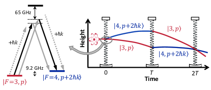
In a light-pulse atom interferometer, recoils from photon-atom interactions are used to split and interfere matter waves (see Fig. 1). These interferometers have been used to measure the gravitational acceleration Peters et al. (2001), rotation Durfee et al. (2006), gravity gradients McGuirk et al. (2002), the fine structure constant Bouchendira et al. (2011), Newton’s gravitational constant Fixler et al. (2007); Rosi et al. (2014), and absolute masses in a proposed revision of the SI Lan et al. (2013); Bouchendira et al. (2013); to test Einstein’s equivalence principle Fray et al. (2004); Bonnin et al. (2013); Tarallo et al. (2014); Schlippert et al. (2014); and have been proposed to measure the free fall of antimatter Hamilton et al. (2014a) and to detect gravitational waves Dimopoulos et al. (2008); Harms et al. (2013); Barrett et al. (2013). The sensitivity of a conventional Mach-Zehnder interferometer increases with the measured phase difference
| (1) |
(where is the initial velocity of the atom), which scales with the pulse separation time and the recoil momentum , where is the effective wavenumber of the photons. State of the art atom interferometers are limited by several engineering boundaries. is limited by the free-fall time in atomic fountains, which are now as high as Sugarbaker et al. (2013); Zhou et al. (2011). Multiphoton interactions can increase the recoil momentum to a multiple of the single photon recoil Müller et al. (2008a); Chiow et al. (2011); Müller et al. (2009); Cladé et al. (2009); McDonald et al. (2013) but are limited by the available laser power (e.g. in Chiow et al. (2009a), in Chiow et al. (2012)). Finally, wavefront distortions spread the local wavevector around its mean, lowering interference contrast and reducing both sensitivity and accuracy. An optical cavity can solve these problems by providing spatial filtering to clean the wavefronts and enhancing laser intensity. However, running an atom interferometer inside an optical cavity presents challenges in keeping the atoms in the relatively small cavity mode volume and having multiple laser frequencies (needed due to recoil frequency shifts, Doppler shifts, and atomic structure) simultaneously resonant with the cavity. Here, we present a cesium atom interferometer inside an in-vacuum optical cavity and demonstrate gravity measurements using less than W of laser power incident on the cavity.
The use of an optical cavity has many advantages. First, laser power limits interferometers using both large momentum transfer beamsplitters and optical lattices. For example, Bragg diffraction requires an intensity proportional to for constant pulse duration, or for constant single-photon scattering rate at an increased detuning Müller et al. (2008b). With resonant enhancement in a cavity, we may achieve -photon Bragg transitions using tens of milliwatts of power from a standard diode laser as opposed to the multiple watt systems recently developed Chiow et al. (2009a, 2012). Similarly, we can reduce scattering from optical lattices by using increased intensity at a larger detuning.
Second, spatial variations in the laser amplitude and phase can reduce interferometric contrast by causing imperfect beamsplitters or unwanted forces in schemes which use an optical lattice to hold atoms Cladé et al. (2010); Charrière et al. (2012). Using the optical cavity as a spatial filter gives well-defined optical phase fronts, increasing the interferometer contrast and reducing systematic errors.
Third, interferometer geometries with enclosed spatial area typically use independent laser beams, whose relative vibration and alignment need to be tightly controlled. Using multiple transverse spatial modes of the optical cavity provides self-aligned interferometry beams. In addition, multiple simultaneous interferometers could provide common-mode rejection of vibrational noise in rotation measurements.
Fourth, many systematics, e.g. gravity gradients, electric and magnetic fields and gradients, are more easily controlled in a small volume. The combination of large momentum transfer and long coherence times in an optical lattice provides high sensitivity in a compact area.
Finally, the position uncertainty typical in atomic fountains, optical wavefront curvature, and Gouy phase shifts are leading systematics in precision experiments Fixler et al. (2007); Bouchendira et al. (2011); Lan et al. (2013); Rosi et al. (2014). The well-defined geometry of the optical cavity reduces them. Counterpropagation of the interferometry beams is also intrinsic in an optical cavity. Optical beam parameters can be determined precisely by measuring the transverse mode spacing of the cavity.
Our experiment uses a two-dimensional magneto-optical trap (2D-MOT) to feed a 3D-MOT through a differential pumping stage. A vacuum of below Torr is maintained inside the main vacuum chamber. All frequencies are stabilized (“locked”) to a reference laser, which is in turn stabilized to a cesium transition by modulation transfer spectroscopy. An experimental run starts with loading cesium atoms into the 3D-MOT in one second. After increasing the detuning of the 3D-MOT beams from to linewidths () and decreasing the optical power, polarization gradients cool the atoms in the state to .
For operation of the interferometer, both frequencies needed to drive Raman or Bragg transitions (the “science laser”) must be kept on resonance with the “science” cavity surrounding our interferometer. We use a second “tracer” laser to stabilize the length of the science cavity. The tracer wavelength of is far from any transition in cesium and has a negligible effect on the atoms. Both lasers are locked to an external transfer cavity whose length is stabilized to the reference laser (see Fig. 2). Before going to the science cavity, the tracer laser is double-passed through a 200 MHz bandwidth acousto-optic modulator (AOM, Brimrose TEF-300-200-0.780) which is tuned such that both lasers are simultaneously resonant with both cavities. Feedback to the science cavity is applied to a piezo-driven diameter flat gold mirror with a feedback bandwidth of Briles et al. (2010). The other cavity mirror has a diameter and radius of curvature. The fundamental longitudinal mode of the cavity has a beam waist of located at the surface of the flat mirror, a finesse of , and a linewidth of . The transverse modes of the cavity are non-degenerate in resonance frequency. For the demonstrations below, where the laser is tuned to only couple strongly to the fundamental mode of the cavity, the incoming interferometry beam is thus effectively spatially filtered.
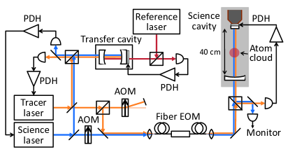
The length of the cavity () was chosen to be nearly an integer number of half wavelengths of the ground state hyperfine splitting of cesium. This allows the two science-laser frequencies needed for Raman transitions to be simultaneously near-resonant with the cavity mode. They are generated from a single laser by a fiber coupled broadband EOM (Eospace). Low phase noise of this frequency is crucial, as it directly enters the measured phase of the interferometer. We use a dielectric resonator oscillator locked to a harmonic of a low-noise quartz crystal. Low phase noise is achieved by using a nonlinear transmission line (Picosecond Pulse Labs) as a harmonic generator. For Bragg diffraction and Bloch oscillations, the science laser passes through an AOM which can be modulated at two frequencies Chiow et al. (2009b).
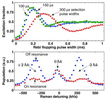
We coarsely select atoms from the MOT that are located in the science cavity mode by first turning on the science laser, detuned from the transition, to create an optical lattice. Atoms not located in the lattice or with too high temperature fall away, leaving atoms. The temperature transverse to the cavity mode increases to as the atoms are loaded into the lattice, but the longitudinal temperature is reduced to upon release from the lattice, most likely by adiabatic expansion. We then optically pump of the atoms to the magnetically insensitive sublevel by applying a magnetic bias field of and a retroreflected beam resonant with the transition with linear polarization parallel to the bias field. A small amount of repump light on the transition is simultaneously applied. For both state and spatial selection, we apply a series of Raman pulses on the clock transition. Each pulse is followed by a clearing beam (either on the cycling or transitions). This both removes atoms that were not initially in the sublevel and preferentially selects atoms towards the center of the cavity mode. Without this spatial selection the widths of the atomic distribution and optical interferometry beams are initially similar and we can achieve a maximum population transfer of only with low contrast on Rabi oscillations. However, using three state selection pulses with a length that maximizes population inversion at the center of the cavity mode allows us to reach population transfer (see Fig. 3, top).
Use of an EOM to generate the Raman frequency pair is a simple way to reach low phase noise, but leads to two sidebands of equal amplitude and opposite phase. At detunings large compared to the hyperfine structure of the excited state the two sideband/carrier pairs drive Raman transitions (see Fig. 1, left) which interfere with a position dependent phase. Because the hyperfine splitting is off (similar to the science cavity line width) from being a multiple of the free spectral range of the science cavity, we may selectively enhance one carrier/sideband pair while suppressing the other, preventing this cancellation.
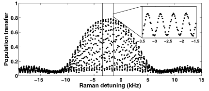
We now present experiments that lead up to our demonstration of intra-cavity atom interferometry: velocity-insensitive and -sensitive Raman pulses, a Raman-Ramsey sequence and, finally, atom interferometry measuring the acceleration due to free fall, . Raman transitions using a copropagating pair of photons are velocity insensitive and transfer negligible momentum to the atoms. We optically drive a combination of two such Raman pulses between the clock states , spaced by a pulse separation time of T = 2 ms to generate the Ramsey fringes shown in Fig. 4. The high contrast demonstrates the good coherence of the process despite the comparable size of the atomic cloud and interferometry beams. This measurement is an optical version of a cesium fountain clock. The optical pulses lead to an AC Stark shift of the transition frequency (e.g. in Fig. 4). By varying the optical intensity while keeping the pulse area constant we find an extrapolated value for the transition frequency at zero intensity of . With microwave pulses we find that, after a correction due to the quadratic Zeeman effect, the measured transition frequency of agrees with the international definition of the second.
Next, we demonstrate velocity-sensitive Raman pulses (using counterpropagating pairs of photons) that transfer a momentum of (Fig. 3, bottom). The falling atoms cause a Doppler shift of the velocity-sensitive transitions which allows us to suppress the unwanted velocity-insensitive transition. As discussed above, detuning the cavity resonance to suppress one EOM sideband further enhances the velocity-sensitive transition.
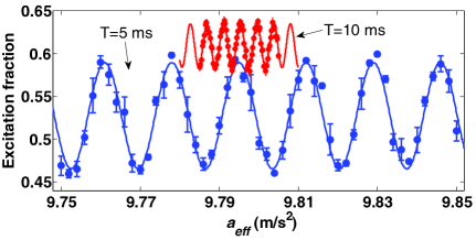
Finally, we demonstrate atom interferometry and perform a gravity measurement by a combination of three velocity sensitive Raman pulses, which constitutes a Mach-Zehnder interferometer. To remain resonant as the freely falling atoms accelerate, the difference frequency in the Raman frequency pair is swept at a rate of ( for ). We detect the interferometer outputs separately by first pushing atoms in either or to the side with our clearing beams and then using fluorescence detection on a CCD camera to spatially resolve the two populations. After normalization to take out atom-number fluctuations, we obtain the interference fringes shown in Fig. 5 by scanning the rate of the frequency ramp. When the frequency ramp matches the acceleration the interferometer phase, , should be zero independent of the pulse separation time . At a maximum pulse separation time we achieve a resolution of , similar to the sensitivity achieved by other compact atom interferometers McGuinness et al. (2012). Additionally, we find that, with as little as of power, and at a smaller single photon detuning of , we attain fringes with contrast for .
We have demonstrated the first atom interferometer in an optical cavity. We have shown that tuning the cavity resonance allows us to selectively address both velocity-sensitive and -insensitive transitions as well as to choose the direction of the momentum kicks in the interferometer, a technique that can be used to reverse many systematic effects. Atoms have been loaded efficiently into the fundamental cavity mode. The setup uses diode lasers only. Using sidebands generated by a wideband EOM to drive Raman transitions avoids the noise usually contributed by a laser phase lock, and is possible without undue systematic effects thanks to the cavity’s rejection of the unwanted sideband. Despite the small size of the cavity mode we achieved high contrast using optical beamsplitters.
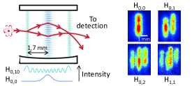
While this proof-of-principle demonstration relied on hyperfine changing Raman transitions, we expect with the power enhancement of the optical cavity that large momentum transfer multiphoton Bragg beamsplitters will be possible Müller et al. (2008b). For the future, the combination of very large momentum transfer and short pulse separation times will make a compact setup which is less sensitive to low-frequency vibrations. Localization of atoms in the cavity, and precise control of the mode of the laser beam should help suppressing major systematics in measurements of the fine structure constant, a proposed mass standard Lan et al. (2013), the gravitational constant Fixler et al. (2007); Rosi et al. (2014), or deviations from Newtonian gravity at short distances Wolf et al. (2007). With these beamsplitters and intracavity optical lattices we plan on exploring a range of applications from inertial sensors Hamilton et al. (2014b) to the first measurement of the gravitational analog of the Aharonov-Bohm effect Hohensee et al. (2012). For example, in Fig. 6 we show one possible realization of a rotational sensor utilizing self-aligned transverse modes of the cavity as well as a demonstration of atoms loaded into such modes. Recently developed methods for both preparing and detecting spin squeezed states Bohnet et al. (2014) in a similar optical cavity could lead to improved sensitivity beyond the standard quantum limit. In addition, the compact size and low power requirements make a cavity interferometer ideal for future mobile or space-based applications Aguilera et al. (2014). Finally, the techniques discussed here may be of interest to proposed experiments using optical cavities to enhance diffraction in systems without easily accessible resonant transitions, e.g. macroscopic masses Asenbaum et al. (2013) or antihydrogen Hamilton et al. (2014a).
Acknowledgements.
We thank E. Simmons and T. Gavrilchenko for their contributions to the apparatus and P. Haslinger, D. Schlippert, and C. Thomas for their comments on the manuscript. J.M.B. thanks the Miller Institute for Basic Research in Science for support. This work has been supported by the David and Lucile Packard Foundation, the Defense Advanced Research Projects Agency, the National Aeronautics and Space Agency and the National Science Foundation.References
- Peters et al. (2001) A. Peters, K. Y. Chung, and S. Chu, Metrologia 38, 25 (2001).
- Durfee et al. (2006) D. S. Durfee, Y. K. Shaham, and M. A. Kasevich, Phys. Rev. Lett. 97, 240801 (2006).
- McGuirk et al. (2002) J. M. McGuirk, G. T. Foster, J. B. Fixler, M. J. Snadden, and M. A. Kasevich, Phys. Rev. A 65, 033608 (2002).
- Bouchendira et al. (2011) R. Bouchendira, P. Cladé, S. Guellati-Khélifa, F. Nez, and F. Biraben, Phys. Rev. Lett. 106, 080801 (2011).
- Fixler et al. (2007) J. B. Fixler, G. T. Foster, J. M. McGuirk, and M. A. Kasevich, Science 315, 74 (2007).
- Rosi et al. (2014) G. Rosi, F. Sorrentino, L. Cacciapuoti, M. Prevedelli, and G. M. Tino, Nature (London) 510, 518 (2014).
- Lan et al. (2013) S.-Y. Lan, P.-C. Kuan, B. Estey, D. English, J. M. Brown, M. A. Hohensee, and H. Müller, Science 339, 554 (2013).
- Bouchendira et al. (2013) R. Bouchendira, P. Cladé, S. Guellati-Khélifa, F. Nez, and F. Biraben, Ann. Phys. (Leipzig) 525, 484 (2013).
- Fray et al. (2004) S. Fray, C. A. A. Diez, T. W. Hänsch, and M. Weitz, Phys. Rev. Lett. 93, 240404 (2004).
- Bonnin et al. (2013) A. Bonnin, N. Zahzam, Y. Bidel, and A. Bresson, Phys. Rev. A 88, 043615 (2013).
- Tarallo et al. (2014) M. G. Tarallo, T. Mazzoni, N. Poli, D. V. Sutyrin, X. Zhang, and G. M. Tino, Phys. Rev. Lett. 113, 023005 (2014).
- Schlippert et al. (2014) D. Schlippert, J. Hartwig, H. Albers, L. L. Richardson, C. Schubert, A. Roura, W. P. Schleich, W. Ertmer, and E. M. Rasel, Phys. Rev. Lett. 112, 203002 (2014).
- Hamilton et al. (2014a) P. Hamilton, A. Zhmoginov, F. Robicheaux, J. Fajans, J. S. Wurtele, and H. Müller, Phys. Rev. Lett. 112, 121102 (2014a).
- Dimopoulos et al. (2008) S. Dimopoulos, P. W. Graham, J. M. Hogan, M. A. Kasevich, and S. Rajendran, Phys. Rev. D 78, 122002 (2008).
- Harms et al. (2013) J. Harms, B. J. J. Slagmolen, R. X. Adhikari, M. C. Miller, M. Evans, Y. Chen, H. Müller, and M. Ando, Phys. Rev. D 88, 122003 (2013).
- Barrett et al. (2013) B. Barrett, P. A. Gominet, E. Cantin, L. Antoni-Micollier, A. Bertoldi, B. Battelier, P. Bouyer, J. Lautier, and A. Landragin, in Atom Interferometry, Proceedings of the International School of Physycs “Enrico Fermi” Course CLXXXVIII, edited by G. M. Tino and M. A. Kasevich (Società Italiana di Fisica and IOS Press, 2013) arXiv:1311.7033 .
- Sugarbaker et al. (2013) A. Sugarbaker, S. M. Dickerson, J. M. Hogan, D. M. S. Johnson, and M. A. Kasevich, Phys. Rev. Lett. 111, 113002 (2013).
- Zhou et al. (2011) L. Zhou, Z. Y. Xiong, W. Yang, B. Tang, W. C. Peng, K. Hao, R. B. Li, M. Liu, J. Wang, and M. S. Zhan, General Relativity and Gravitation, Gen. Relativ. Gravit. 43, 1931 (2011).
- Müller et al. (2008a) H. Müller, S.-w. Chiow, Q. Long, S. Herrmann, and S. Chu, Phys. Rev. Lett. 100, 180405 (2008a).
- Chiow et al. (2011) S. W. Chiow, T. Kovachy, H.-C. C. Chien, and M. A. Kasevich, Phys. Rev. Lett. 107, 130403 (2011).
- Müller et al. (2009) H. Müller, S. W. Chiow, S. Herrmann, and S. Chu, Phys. Rev. Lett. 102, 240403 (2009).
- Cladé et al. (2009) P. Cladé, S. Guellati-Khélifa, F. Nez, and F. Biraben, Phys. Rev. Lett. 102, 240402 (2009).
- McDonald et al. (2013) G. D. McDonald, C. C. N. Kuhn, S. Bennetts, J. E. Debs, K. S. Hardman, M. Johnsson, J. D. Close, and N. P. Robins, Phys. Rev. A 88, 053620 (2013).
- Chiow et al. (2009a) S. W. Chiow, S. Herrmann, H. Müller, and S. Chu, Opt. Express 17, 5246 (2009a).
- Chiow et al. (2012) S. Chiow, T. Kovachy, J. M. Hogan, and M. A. Kasevich, Opt. Lett. 37, 3861 (2012).
- Müller et al. (2008b) H. Müller, S. W. Chiow, and S. Chu, Phys. Rev. A 77, 023609 (2008b).
- Cladé et al. (2010) P. Cladé, T. Plisson, S. Guellati-Khélifa, F. Nez, and F. Biraben, Eur. Phys. J. D 59, 349 (2010).
- Charrière et al. (2012) R. Charrière, M. Cadoret, N. Zahzam, Y. Bidel, and A. Bresson, Phys. Rev. A 85, 013639 (2012).
- Briles et al. (2010) T. C. Briles, D. C. Yost, A. Cingöz, J. Ye, and T. R. Schibli, Opt. Express 18, 9739 (2010).
- Chiow et al. (2009b) S. W. Chiow, S. Herrmann, S. Chu, and H. Müller, Phys. Rev. Lett. 103, 050402 (2009b).
- McGuinness et al. (2012) H. J. McGuinness, A. V. Rakholia, and G. W. Biedermann, Appl. Phys. Lett. 100, 011106 (2012).
- Wolf et al. (2007) P. Wolf, P. Lemonde, A. Lambrecht, S. Bize, A. Landragin, and A. Clairon, Phys. Rev. A 75, 063608 (2007).
- Hamilton et al. (2014b) P. Hamilton, M. Jaffe, J. M. Brown, B. Estey, H. Muller, R. Compton, and K. Nelson, in Inertial Sensors and Systems (ISISS), 2014 International Symposium on (IEEE, 2014) pp. 1–4.
- Hohensee et al. (2012) M. A. Hohensee, B. Estey, P. Hamilton, A. Zeilinger, and H. Müller, Phys. Rev. Lett. 108, 230404 (2012).
- Bohnet et al. (2014) J. G. Bohnet, K. C. Cox, M. A. Norcia, J. M. Weiner, Z. Chen, and J. K. Thompson, Nature Photonics 8, 731 (2014).
- Aguilera et al. (2014) D. N. Aguilera et al., Class. Quantum Gravity 31, 115010 (2014).
- Asenbaum et al. (2013) P. Asenbaum, S. Kuhn, S. Nimmrichter, U. Sezer, and M. Arndt, Nature Communications 4, 2743 (2013).