Cyber-Virtual Systems: Simulation, Validation & Visualization
Abstract
We describe our ongoing work and view on simulation, validation and visualization of cyber-physical systems in industrial automation during development, operation and maintenance. System models may represent an existing physical part – for example an existing robot installation – and a software simulated part – for example a possible future extension. We call such systems cyber-virtual systems. In this paper, we present the existing VITELab infrastructure for visualization tasks in industrial automation. The new methodology for simulation and validation motivated in this paper integrates this infrastructure. We are targeting scenarios, where industrial sites which may be in remote locations are modeled and visualized from different sites anywhere in the world. Complementing the visualization work, here, we are also concentrating on software modeling challenges related to cyber-virtual systems and simulation, testing, validation and verification techniques for them. Software models of industrial sites require behavioural models of the components of the industrial sites such as models for tools, robots, workpieces and other machinery as well as communication and sensor facilities. Furthermore, collaboration between sites is an important goal of our work.
1 INTRODUCTION
Operation, development, maintenance (including modifications and extensions) of industrial automation facilities like factories or mining sites profit from software support such as software based monitoring, controlling and collaboration tools. This requires visualization capacities as well as software models of the physical entities involved and ways to reason about them. Industrial automation facilities typically comprise machinery like robots and their components. Components may serve as actuators: tools, conveyor belts, work pieces or pipes, valves and pumps in cases were fluids or gases are processed. Sensors can be found throughout industrial automation sites. The data gathered from the sensors may be stored in a central facility.
Hardware-in-the-loop (HIL) approaches [Schlager, 2008] are now standard in the development of system components in domains such as automative systems, e.g., [Isermann et al., 1999], avionics and also in industrial automation. In HIL, parts of a system are simulated in software to test a distinct system component. In this paper, we are going one step further and aim at simulating different parts of an industrial site. We do not restrict our approach to the development, but also aim at supporting operation and maintenance of industrial automation facilities. Furthermore, we aim at visualizing remote facilities or parts of them. This is especially crucial when developing, operating or maintaining industrial sites located in areas that are difficult to access such as mines and oil rigs and for collaboration between different sites and sharing knowledge between them.
In the case where components of a system are manufactured at different places, transport from component development and production locations to integration and deployment sites can significantly increase the whole development costs as well as time. Integration can reveal additional work tasks and further transportation of the system’s parts may be necessary. If a system’s components are bulky or heavy, this may also delay optimization and correction.
For this reason, we present an existing visualization infrastructure - the Virtual Interoperability Test Lab (VITELab)111VITELab is an eResearch facility of the Australia-India Research Centre for Automation Software Engineering (AICAUSE), a partnership between RMIT University and the ABB Group (Australia and India), http://rmit.edu.au/research/aicause. a global laboratory connecting industry and university sites and providing a collaboration platform for experimental design and testing of cyber-physical systems. Among its aims are to reduce development costs by simulating and virtually testing possible deployments before the system is actually physically set up. We also present the corresponding new and ongoing research directions towards combining visualization and software support for reasoning about industrial automation facilities. The ideas featured in this paper comprise the following ingredients:
-
•
The use of VITELab, in particular the Global Operations Visualization (GOV) Lab, a high resolution multi-screen visualization facility.
-
•
Software models for system components that comprise spatio-temporal information about a component’s behavior and ways to reason about them, testing and simulation.
-
•
The combination and integration of these for industrial automation.
Our work is a step towards software solutions facilitating global collaboration between developers, operators and maintenance of industrial sites.
2 RELATED WORK
Modelling aspects Different languages exist for the modeling of embedded and automation systems. Standards like IEC 61131-3 and IEC 61499 target the software part of control systems and thus specify the behavior of machinery. In the scientific community different modeling languages such as the Petri-Net semantics based BIP [Basu et al., 2006] for distributed asynchronous systems and Modelica, providing means for modeling and simulation of systems have been established, cf. [Donath et al., 2008], [Fritzson, 2004], [Anderson and Fritzson, 2013]. Modelica is object-oriented and its latest extensions allow modelling of system requirements [Tundis et al., 2013] as well as simulation of technical and physical systems [Fritzson, 2011]. Modeling theories for distributed hybrid system such as SHIFT [Deshpande et al., 1997] and R-Charon [Kratz et al., 2006] guarantee a complete simulation and compilation of the models, but do not support verification or analysis of the system on the modeling level. Same limitations also apply to the input language of the model checkers UPPAAL [Behrmann et al., 2004] and PHAVer [Beek et al., 2006]: the verification capabilities do not match the whole expressiveness of the modeling languages.
Assigning semantics to logical entities for categorizing and reasoning about them is a one goal of our models for industrial automation facilities. The concept has been made popular in the context of the semantic web [Berners-Lee et al., 2001] and ontologies [Staab et al., 2001].
Spatial aspects The modeling of industrial automation sites involves spatial aspects. For example, robots must ensure a behavior that guarantees collision avoidance and the correct handling of workpieces. Systems that comprising thermal aspects like heat exchangers need adequate models to cover their behavior. SpaceEx [Frehse et al., 2011] allows the modeling of continuos hybrid systems based on hybrid automata. It can be used for computing overapproximations of the space occupied by objects. A process algebra for 3D objects is provided in [Cardelli and Gardner, 2010]. Results on spatial interpretations are explained in [Hirschkoff et al., 2003]. A quantifier-free rational fragment of logic suitable for describing spatial scenarios has been shown to be decidable in [Dal Zilio et al., 2004]. Logics for spatio-temporal reasoning go back to the seventies. The Region Connection Calculus (RCC) [Bennett et al., 2002] includes spatial predicates of separation. RCC features predicates indicating that regions do not share points at all, points on the boundary of regions are shared, internal contact where one region is included and touches on the boundary of another from the inside, overlap of regions, and inclusion.
Cyber-physical aspects Many approaches on mechatronic/cyber-physical systems omit an abstract logical level of the system representation and lose the advantages of the abstract representation. The work presented in [Vogel-Heuser et al., 2011] defines an extensive support to the components communication and time requirements, while the model discussed in [Hadlich et al., 2011] proposes a complete model of the processes with communication. In traditional development of embedded systems e.g., [Berger, 2002], the system is usually separated into software and hardware parts as soon as possible, at an early stage of the development process. This does not always benefit the development process, because when using an abstract level of modeling the difference in the nature of components does not necessarily play an important role. [Sapienza et al., 2012] and [Spichkova and Campetelli, 2012] independently suggest to use a platform-independent design in the early stages of system development. The approach presented in [Sapienza et al., 2012] introduces the idea of pushing hardware- and software-dependent design as late as possible, however, the question of the current practical and fundamental limitations of logical modeling in comparison to cyber-physical testing, is not completely answered. In comparison to [Sapienza et al., 2012], the focus of [Spichkova and Campetelli, 2012] is on reutilisation and generalisation of two existing software systems development methodologies (both elaborated according to the results of the case studies motivated and supported by DENSO Corporation and Robert Bosch GmbH) for application within the cyber-physical domain to benefit from the advantages these techniques have shown. The question, how deep we can go on the modeling of cyber-physical systems on the logical level is still open in both approaches. The goals presented here are also related to hybrid commissioning [Dominka et al., 2007].
Early analysis aspects The idea of early analysis of critical system faults has the goal to identify faults which mutate the safety critical behaviour of the system, and to identify test scenarios which can expose such faults from an abstract modeling level, i.e. by generation of tests (both for real system and its model) from formal specifications or from the CASE tool models (cf., e.g., [Hazra et al., 2013, Broy et al., 2005, Pretschner and Philipps, 2005]). The approach has certain limitations due the abstract nature of the formal model serving as a base for the test generation as well as an underlying assumption of existence of a precise formal model of the system being developed. Even when taking into account these limitations and assumptions, these approaches allow automatization of test case design and make the design process more stringent. VITELab and the described research complements commercially available visualization software for collaboration purposes in industrial automation such as DELMIA222http://www.3ds.com/products-services/delmia/products/all-delmia-products/. The approach described here, is building on (semi-)formal models which carry semantic meaning and are suitable for automatic interpretation and processing, whereas the DELMIA focus is even more on visualization.
3 FROM CYBER-PHYSICAL TO CYBER-VIRTUAL SYSTEMS
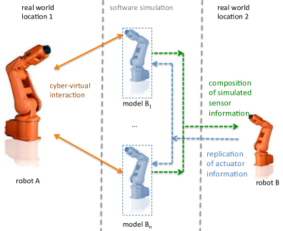
Let us discuss an example scenario based on the ideas of the virtual interoperation testing. In an industrial plant we require the integration/interoperability of bulky/heavy robots (cf. Figure 1): a robot of the type (lets call it robot ) is assembled in location , the other robots are of a different type and are assembled in a different location location . The robots are in different locations and making them work together in a different shared deployment location requires extensive simulation, testing and collaboration.
Assuming in addition that the robots of type perform simultaneously similar movements and actions (e.g., they stamp similar details on workpieces on a conveyor belt and are doing the same movements, even in the case their stamps are different), we can simulate their behaviour using a single robot : its actuator information will be replicated to obtain virtual models , and its sensor information will be extended by the composition of the modeled sensor information from . The sensor information of the robot will be a composition of the real sensor data and the sensor data modeled according to the actions of .
Thus, to check the interoperability of the robot and robots of the type on the level of virtual interoperability testing, we need only two real robots: a robot and a robot . Moreover, they could be located in and respectively, because the simulator and visualization facility may take the role of a physical medium between them, allowing to ignore the real distance between robots and also allowing to have a visualisation of the test and simulation not only at and , but also on the third place , where the corresponding laboratory is located.
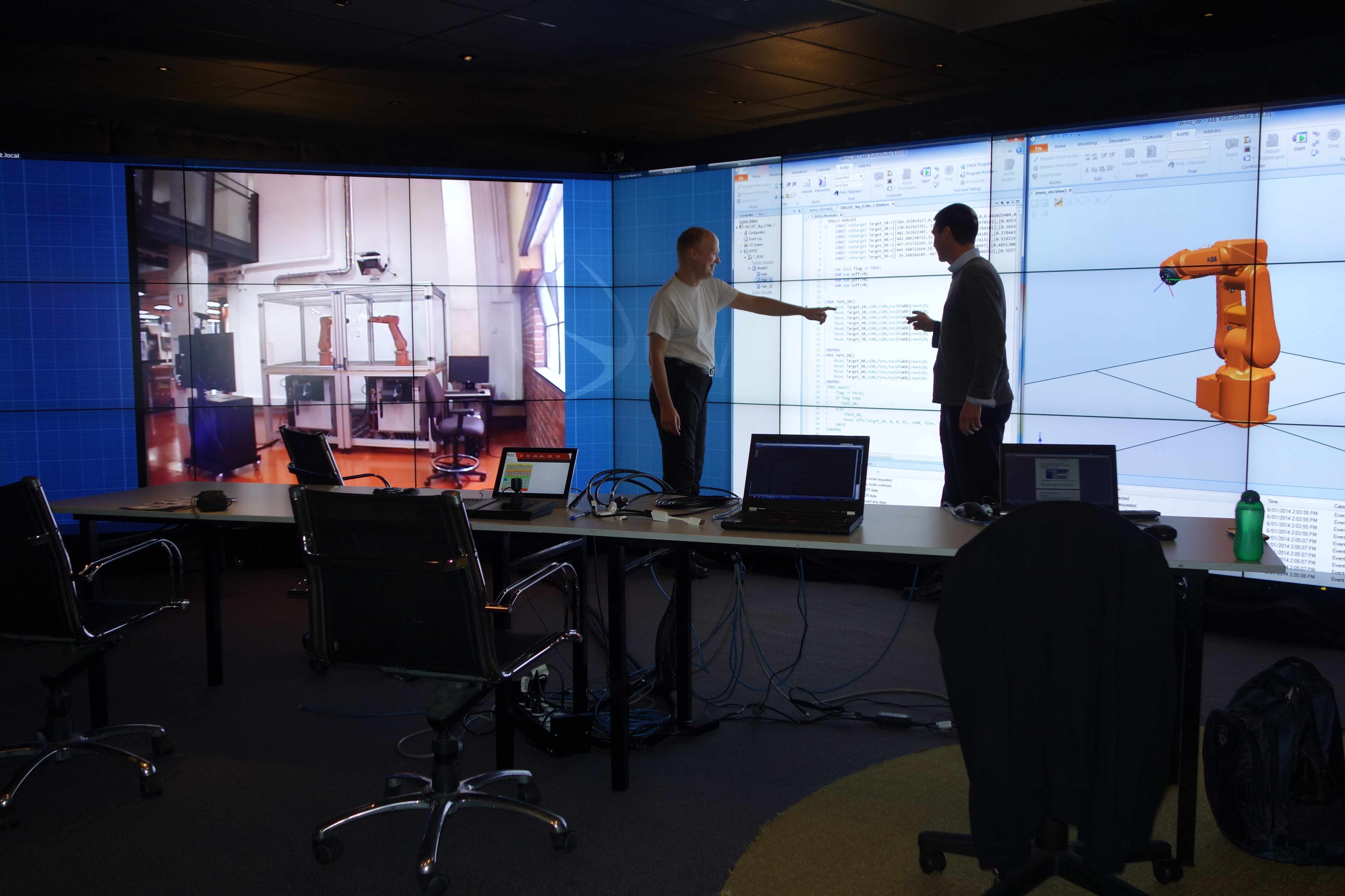
General ideas for using the virtual interoperability test lab (VITELab) for the use of remote cyber-physical integration/interoperability testing in a virtual environment as a middle step between an abstract modelling and real testing were presented in [Spichkova et al., 2013a]. Figure 2 shows the VITELab facility in operation, viewed from the GOV Lab. VITELab gives a platform for a new level of simulation and integration: interoperability simulation and testing is performed early and remotely, for example while cyber-physical components are in the prototyping stage i.e. on the workbench: individual components (e.g., robots, manufacturing cells), are connected in a suitable virtual environment, without being deployed at the same place physically. Successful testing and simulation could significantly reduce the well-documented costs arising from discovery of design faults after implementation.
Research connected to VITElab is influenced by larger cooperations in the industrial automation domain. Remote integration and testing allows for an integration and testing phase of a real system assuming a certain level of abstraction where the network, the virtual environment and the remote embodiments may be abstractions themselves. This level of abstraction includes real physical components of the system (in the case of the VITElab project, e.g., real robots and production plants) and more characteristics of the network, environment and embodiments. Our models and their visualization can give us the possibility to identify (i) a number of problems and inconsistencies on the early stage of system development and verify especially important system’s properties before the real system is build and integrated, and (ii) possible weak points in the system (such as some timing properties, feature interactions, component dependancies) which we should focus on, during the testing phase.
4 RESEARCH CHALLENGES AND CORRESPONDING PROJECTS
This section presents research challenges connected to cyber-virtual systems, VITELab, simulation and validation in more detail.
Main directions for research
We have identified the following research challenges in our scenario:
-
•
Simulation and the visualization of simulation runs.
-
•
Testing, verification and validation of cyber-virtual scenarios.
-
•
Gaining expertise and knowledge from joint work using visualization and simulation.
-
•
Sharing and making expertise and knowledge available for similar development projects and for related operation and maintenance tasks in related facilities.
Software Models for Industrial Plants
In our work, we propose two ingredients related to software models for addressing these challenges:
-
•
(Semi-)formal descriptions based on human factors approaches to achieve better readability/usability and understandability.
-
•
Spatial behavioral models that capture the characteristics of entities and components in industrial automation. We are interested in establishing a type system for these components.
Existing VITELab projects
The research challenges identified in the context of VITELab fall into the network, cloud and distributed computing areas, and are covered by the following ongoing projects:
-
•
Network connectivity between sites with specialist equipment is supported by dedicated links and research software stacks.
-
•
The Cyber-physical Simulation Rack (CSRack), is a multi-node cloud server rack with attached RAID storage provides parallel cloud computing capability to support modeling and simulation and the capability to act as a ’cloudlet’ gateway to major national and international cloud facilities such as NeCTAR333National eResearch Collaboration Tools and Resources Project, https://www.nectar.org.au.
-
•
The Global Operations Visualization (GOV) Lab project, provides videoconference and streaming capability to remote sites combined with a large high resolution tiled display wall.
-
•
The Advanced Manufacturing Robot Interoperation Test (AMRIT) lab provides industrial robots connected to the GOV lab. The robots comprise arms, sensors and cameras as “eyes on the robots”.
Further research challenges exist in the connection of software based development tools for industrial automation systems to the described infrastructure. Such tools may need to undergo a redesign of the software architecture to enable this, cf. [Peake et al., 2013].
5 From (Semi-)Formal Methods to Visualization & Validation
A starting point for our work is a HIL approach and is depicted in Figure 3. Here, the interplay of a physical robot with a virtual simulated robot is shown. The actions of the physical robot to the environment are observed passed to the robot simulation and reacting actions are calculated. These actions are (by)passed to the sensors of the physical robot to simulate the interplay.
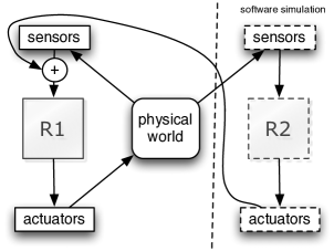
The interplay can be analyzed both by software tools as well as human inspection. The human based analysis profits from visualisation capabilities for the display of the simulated robot and the monitoring of the physical counterpart.
Human Factors and Formal Models
To enable simulations we need (semi-)formal descriptions of robot behavior, which should not only fit for the simulation purposes but also be readable for system/verification engineers. In our approach we follow the ideas based on human factor analysis within formal methods [Spichkova, 2013a, Spichkova, 2012]. This allows to have short and readable specifications of component behavior. It is appropriate for switching between different modeling, specification and programming languages and is suitable for the application of specification, reasoning and proof methodology [Spichkova et al., 2013b, Spichkova, 2007].
Formal Proofs and Verification
In the case of formal proofs, one of the main points of this methodology is an alignment of the future proofs during the specification phase to make the proofs simpler and appropriate for application in practice. One direction for reasoning about a system represented in a formal specification framework, is the verification of its properties by translating the specification to a Higher-Order Logic and subsequently using the theorem prover following [Spichkova, 2013b].
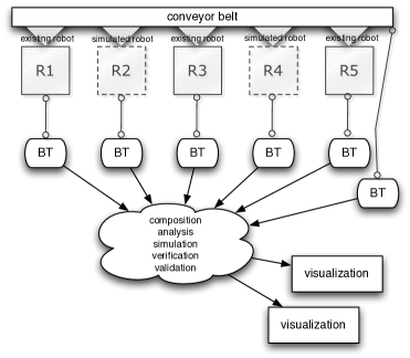
Spatial Behavioral Types
Our (semi-)formal models comprise spatial behavioural. This can be assigned to both physical and virtual simulated robots, their components and other entities interacting with them as shown in Figure 4. Following the ideas presented in [Blech et al., 2012] these spatial behavioural models can serve as a type system similar to types systems in higher programming languages like C and Java which come with basic types like integers, Strings and floating point values as well as composed types like records or classes. Here, we regard (spatial) Behavioural Types (BT). BT act as types for virtual or physical entities in our automation scenarios. They are characterised by the following core concepts:
-
•
Abstraction. BT represent aspects of robots, robot components and other entities in industrial automation. BT abstract from details concerning interactions and internal structure.
-
•
Conformance. Type conformance of BT is used to relate entities in industrial automation correctly to a BT.
-
•
Refinement. BT should comprise a notion of spatio-behavioral refinement that allows replacing a component by a refined one. For example, the concept of refinement shall allow replacing a robot by a newer version that essentially provides the same functionality plus some new features.
-
•
Compatibility. Compatibility checking of BT is used to decide whether a component does indeed match required needs based on provided and expected BT. It should be decidable and automatic.
-
•
Inference. A BT framework should allow to infer composed BT. For example, the BT of a robot may be inferred from the BT of its components.
Spatial Behavioural Types for Simulation and Validation
BT can serve as a specification basis for the components of robots and the robots composed of them.
BT can be used to build models of industrial automation facilities. Using BT based specifications, we can perform:
-
•
Simulation and visualization for human inspection and collaboration between developers, operators and maintenance personnel.
-
•
Automatic spatio-temporal reasoning for collision detection of robots and other entities.
-
•
Checking automatically the required sensor ranges and regions affected by physical entities.
-
•
Guaranteeing correct interplay of tools and workpieces in time and space.
-
•
Simulating the replacement of an entity such as a robot arm by another (refined) version.
-
•
Documenting behavior of system installations and sharing this for collaboration.
The BT concept is following the idea of interface automata [de Alfaro and Henzinger, 2001]. It has been proposed as a type system for OSGi systems in the past [Blech et al., 2012]. Theorem prover export and interactive verification of properties were studied in [Blech and Schätz, 2012] and may be an issue for future work together with human-factor analysis. Checking compatibility and means to make behavioral system descriptions compatible were examined in [Blech, 2013]. For checking the spatio-temporal properties in our scenarios we incorporate the BeSpaceD [Blech and Schmidt, 2013] tool. Checks in BeSpaceD are done by converting spatio-temporal models or BT and required properties into SMT and SAT problems and applying suitable solving techniques such as the z3 SMT solver [De Moura and Bjørner, 2008].
6 CONCLUSIONS
The presented research is ongoing work and part of larger cooperations with an industrial automation company. In this paper, we presented an overview on the existing VITELab infrastructure facilitating remote collaboration by large screen/multi screen visualization. The aim of this infrastructure is to reduce the development costs by simulating and virtually testing possible deployments before the system is actually physically set up. We have highlighted connected research questions, as well as explained the VITELab applications in operating, developing and maintaining industrial automation facilities. The connection to spatial behavioral models and a related type system for the simulation of industrial automation facilities and the connection to visualization capacities was presented in more detail.
Acknowledgements
We would like to thank staff from RMIT ITS, PropertyServices, eResearch and the VITELab team, in particular Lasith Fernando, Ravi Sreenivasamurthy and Garry Keltie.
REFERENCES
- Anderson and Fritzson, 2013 Anderson, A. and Fritzson, P. (2013). Models for Distributed Real-Time Simulation in a Vehicle Co-Simulator Setup. In Nilsson, H., editor, Proceedings of the 5th International Workshop on Equation-Based Object-Oriented Modeling Languages and Tools. Linkoping University Electronic Press.
- Basu et al., 2006 Basu, A., Bozga, M., and Sifakis, J. (2006). Modeling heterogeneous real-time components in bip. In 4th IEEE International Conference on Software Engineering and Formal Methods (SEFM), pages 3–12. IEEE.
- Beek et al., 2006 Beek, D. A. V., Man, K. L., Reniers, M. A., Rooda, J. E., and Schiffelers, R. R. H. (2006). Syntax and consistent equation semantics of hybrid Chi. In Journal of Logic and Algebraic Programming, pages 129–210.
- Behrmann et al., 2004 Behrmann, G., David, A., and Larsen, K. (2004). A Tutorial on Uppaal. In Bernardo, M. and Corradini, F., editors, Formal Methods for the Design of Real-Time Systems, volume 3185 of LNCS, pages 200–236. Springer.
- Bennett et al., 2002 Bennett, B., Cohn, A. G., Wolter, F., and Zakharyaschev, M. (2002). Multi-dimensional modal logic as a framework for spatio-temporal reasoning. Applied Intelligence, 17(3):239–251.
- Berger, 2002 Berger, A. (2002). Embedded Systems Design: An Introduction to Processes, Tools, and Techniques. CMP Books.
- Berners-Lee et al., 2001 Berners-Lee, T., Hendler, J., Lassila, O., et al. (2001). The semantic web. Scientific american, 284(5):28–37.
- Blech, 2013 Blech, J. O. (2013). Towards a framework for behavioral specifications of osgi components. In 11th International Workshop on Formal Engineering approaches to Software Components and Architectures (FESCA), pages 79–93.
- Blech et al., 2012 Blech, J. O., Falcone, Y., Rueß, H., and Schätz, B. (2012). Behavioral specification based runtime monitors for osgi services. In Leveraging Applications of Formal Methods, Verification and Validation. Technologies for Mastering Change, pages 405–419. Springer Berlin Heidelberg.
- Blech and Schätz, 2012 Blech, J. O. and Schätz, B. (2012). Towards a formal foundation of behavioral types for uml state-machines. ACM SIGSOFT Software Engineering Notes, 37(4):1–8.
- Blech and Schmidt, 2013 Blech, J. O. and Schmidt, H. (2013). Towards modeling and checking the spatial and interaction behavior of widely distributed systems. In Improving Systems and Software Engineering Conference.
- Broy et al., 2005 Broy, M., Jonsson, B., Katoen, J.-P., Leucker, M., and Pretschner, A. (2005). Model-Based Testing of Reactive Systems: Advanced Lectures (LNCS). Springer.
- Cardelli and Gardner, 2010 Cardelli, L. and Gardner, P. (2010). Processes in space. In Programs, Proofs, Processes, pages 78–87. Springer.
- Dal Zilio et al., 2004 Dal Zilio, S., Lugiez, D., and Meyssonnier, C. (2004). A logic you can count on. In ACM SIGPLAN Notices, volume 39, pages 135–146. ACM.
- de Alfaro and Henzinger, 2001 de Alfaro, L. and Henzinger, T. A. (2001). Interface automata. SIGSOFT Softw. Eng. Notes, 26(5):109–120.
- De Moura and Bjørner, 2008 De Moura, L. and Bjørner, N. (2008). Z3: An efficient smt solver. In Tools and Algorithms for the Construction and Analysis of Systems, pages 337–340. Springer.
- Deshpande et al., 1997 Deshpande, A., G ll , A., Gollu, A., and Varaiya, P. (1997). Shift: A Formalism and a Programming Language for Dynamic Networks of Hybrid Automata.
- Dominka et al., 2007 Dominka, S., Schiller, F., and Kain, S. (2007). Hybrid commissioning—from hardware-in-the-loop simulation to real production plants. In Proceedings of the 18th IASTED International Conference on Modeling and Simulation (MS’07), pages 544–549.
- Donath et al., 2008 Donath, U., Haufe, J., Blochwitz, T., and Neidhold, T. (2008). A new Approach for Modeling and Verification of Discrete Control Components within a Modelica Environment.
- Frehse et al., 2011 Frehse, G., Le Guernic, C., Donzé, A., Cotton, S., Ray, R., Lebeltel, O., Ripado, R., Girard, A., Dang, T., and Maler, O. (2011). Spaceex: Scalable verification of hybrid systems. In Computer Aided Verification, pages 379–395. Springer.
- Fritzson, 2004 Fritzson, P. (2004). Principles of Object-Oriented Modeling and Simulation with Modelica 2.1. Wiley-IEEE Computer Society Press.
- Fritzson, 2011 Fritzson, P. (2011). Introduction to Modeling and Simulation of Technical and Physical Systems with Modelica. Wiley-IEEE Computer Society Press.
- Hadlich et al., 2011 Hadlich, T., Diedrich, C., Eckert, K., Frank, T., Fay, A., and Vogel-Heuser, B. (2011). Common communication model for distributed automation systems. In 9th IEEE International Conference on Industrial Informatics, IEEE INDIN.
- Hazra et al., 2013 Hazra, A., Ghosh, P., Vadlamudi, S. G., Chakrabarti, P. P., and Dasgupta, P. (2013). Formal methods for early analysis of functional reliability in component-based embedded applications. Embedded Systems Letters, 5(1):8–11.
- Hirschkoff et al., 2003 Hirschkoff, D., Lozes, É., and Sangiorgi, D. (2003). Minimality results for the spatial logics. In FST TCS 2003: Foundations of Software Technology and Theoretical Computer Science, pages 252–264. Springer.
- Isermann et al., 1999 Isermann, R., Schaffnit, J., and Sinsel, S. (1999). Hardware-in-the-loop simulation for the design and testing of engine-control systems. Control Engineering Practice, 7(5):643–653.
- Kratz et al., 2006 Kratz, F., Sokolsky, O., Pappas, G. J., and Lee, I. (2006). R-Charon, a Modeling Language for Reconfigurable Hybrid Systems. In Hybrid Systems: Computation and Control (HSCC), pages 392–406.
- Peake et al., 2013 Peake, I., Blech, J. O., and Fernando, L. (2013). Towards reconstructing architectural models of software tools by runtime analysis. In 3rd International Workshop on Experiences and Empirical Studies in Software Modelling.
- Pretschner and Philipps, 2005 Pretschner, A. and Philipps, J. (2005). Methodological Issues in Model-Based Testing. Model-Based Testing of Reactive Systems, pages 181–291.
- Sapienza et al., 2012 Sapienza, G., Crnkovic, I., and Seceleanu, T. (2012). Towards a methodology for hardware and software design separation in embedded systems. In Proc. of the Seventh International Conference on Software Engineering Advances (ICSEA), pages 557–562. IARIA.
- Schlager, 2008 Schlager, M. (2008). Hardware-in-the-loop simulation.
- Spichkova, 2007 Spichkova, M. (2007). Specification and Seamless Verification of Embedded Real-Time Systems: FOCUS on Isabelle. PhD thesis, Technische Universität München.
- Spichkova, 2012 Spichkova, M. (2012). Human Factors of Formal Methods. In Proc. of IADIS Interfaces and Human Computer Interaction. IHCI 2012.
- Spichkova, 2013a Spichkova, M. (2013a). Design of formal languages and interfaces: “formal” does not mean “unreadable”. In Blashki, K. and Isaias, P., editors, Emerging Research and Trends in Interactivity and the Human-Computer Interface. IGI Global.
- Spichkova, 2013b Spichkova, M. (2013b). Stream Processing Components: Isabelle/HOL Formalisation and Case Studies. Archive of Formal Proofs.
- Spichkova and Campetelli, 2012 Spichkova, M. and Campetelli, A. (2012). Towards system development methodologies: From software to cyber-physical domain. In First International Workshop on Formal Techniques for Safety-Critical Systems (FTSCS’12).
- Spichkova et al., 2013a Spichkova, M., Schmidt, H., and Peake, I. (2013a). From abstract modelling to remote cyber-physical integration/interoperability testing. In Improving Systems and Software Engineering Conference.
- Spichkova et al., 2013b Spichkova, M., Zhu, X., and Mou, D. (2013b). Do we really need to write documentation for a system? In International Conference on Model-Driven Engineering and Software Development (MODELSWARD’13).
- Staab et al., 2001 Staab, S., Studer, R., Schnurr, H.-P., and Sure, Y. (2001). Knowledge processes and ontologies. Intelligent Systems, IEEE, 16(1):26–34.
- Tundis et al., 2013 Tundis, A., Rogovchenko-Buffoni, L., Fritzson, P., and Garro, A. (2013). Modeling System Requirements in Modelica: Definition and Comparison of Candidate Approaches. In Nilsson, H., editor, Proceedings of the 5th International Workshop on Equation-Based Object-Oriented Modeling Languages and Tools. Linkoping University Electronic Press.
- Vogel-Heuser et al., 2011 Vogel-Heuser, B., S., F., Werner, T., and Diedrich, C. (2011). Modeling network architecture and time behavior of distributed control systems in industrial plant. In 37th Annual Conference of the IEEE Industrial Electronics Society, IECON.