Cyclic Delay Transmission for Vector OFDM Systems
Abstract
Single antenna vector OFDM (V-OFDM) system has been proposed and investigated in the past. It contains the conventional OFDM and the single carrier frequency domain equalizer (SC-FDE) as two special cases and is flexible to choose any number of symbols in intersymbol interference (ISI) by choosing a proper vector size. In this paper, we develop cyclic delay diversity (CDD) transmission for V-OFDM when there are multiple transmit antennas (CDD-V-OFDM). Similar to CDD-OFDM systems, CDD-V-OFDM can also collect both spatial and multipath diversities. Since V-OFDM first converts a single input single output (SISO) ISI channel to a multi-input and multi-output (MIMO) ISI channel of order/length times less, where is the vector size, for a given bandwidth, the CDD-V-OFDM can accommodate times more transmit antennas than the CDD-OFDM does to collect all the spatial and multipath diversities. This property will specially benefit a massive MIMO system. We show that with the linear MMSE equalizer at each subcarrier, the CDD-V-OFDM achieves diversity order , where is the transmission rate, is the number of transmit antennas, and is the ISI channel length between each transmit and receive antenna pair. Simulations are presented to illustrate our theory.
Index Terms:
Cyclic delay diversity (CDD) transmission, vector OFDM (V-OFDM), massive MIMO, spatial and multi-path diversities, MMSE receiver.I Introduction
Orthogonal frequency division multiplexing (OFDM) systems have been well accepted in broadband wireless communications, such as LTE [1], WiMAX [2] and WiFi [2] systems. It is mainly because OFDM converts an ISI channel to multiple ISI free subchannels by using IDFT/DFT operations. When transmission data rates get higher and higher, signal bandwidths need to get wider and wider, which causes communication/ISI channel lengths longer and longer. A longer ISI channel forces the number of the subcarriers in an OFDM system larger in order to provide ISI free subchannels. A larger may cause more difficulties in OFDM implementations, such as high peak-to-average power ratio (PAPR), etc.
Single antenna V-OFDM is proposed in [3, 4], which first converts a SISO ISI channel into an equivalent MIMO channel with memory, but the MIMO channel memory length (or order) is reduced by times compared to that of the SISO ISI channel, and then converts the equivalent MIMO channel with memory to multiple MIMO subchannels without memory. Since the MIMO channel length is times less, the CP length added to the V-OFDM can be also reduced by times compared to that of the OFDM for the SISO ISI channel. The cost for V-OFDM is that, although the multiple MIMO subchannels are constant vector/matrix channels and do not have memory, in each MIMO subchannel, the information symbols in each signal vector are still ISI channel. In other words, V-OFDM does not convert an ISI channel completely to multiple ISI free subchannels as OFDM does, but converts an ISI channel to multiple sub-channels with a fixed and flexible number, , of ISI symbols in each subchannel and can be arbitrarily chosen. As the two extreme cases of , the conventional OFDM and single-carrier frequency domain equalizer (SC-FDE) correspond to the cases when and , respectively. With V-OFDM, when an ISI channel length increases as its bandwidth increases, the number of subcarriers may be fixed, while the vector size can be increased, which may be an alternative choice for a wide band system.
In wireless communications, an important technique to combat fading is to use multiple transmit antennas to collect spatial diversity [5, 6, 7]. For a broadband MIMO system, there are two kinds of diversities, namely spatial diversity and multipath diversity. To collect both spatial and multipath diversities, space-frequency/time coding has been proposed in the literature to code information symbols across not only antennas but also subcarriers, see for example [8, 9, 10, 11], which, however, has a high decoding complexity at the receiver. A much simpler technique to collect both spatial and multipath diversities is the cyclic delay diversity (CDD) technique [12, 13, 14, 15, 16, 17, 18, 19, 20, 21], where the other transmit antennas transmit cyclically delayed versions of the signal transmitted at the first transmit antenna in every OFDM block. With CDD-OFDM, to collect the full spatial and multipath diversities, the product of the number of transmit antennas with the ISI channel length cannot be more than the number of subcarriers. When transmit antenna number is large, the full spatial and multipath diversities may not be collected by using the CDD technique when the number of subcarriers and the channel bandwidth are fixed.
In this paper, we propose a CDD transmission for V-OFDM (CDD-V-OFDM) for multiple transmit antenna systems. Similar to the CDD-OFDM, the other transmit antennas transmit cyclically delayed versions of the V-OFDM signals the first transmit antenna transmits in every V-OFDM block. Since an ISI channel length can be equivalently reduced by times in V-OFDM, with our proposed CDD-V-OFDM, for a fixed channel bandwidth (or channel length) and a fixed IDFT/DFT size (or number of subcarriers), CDD-V-OFDM can accommodate times more transmit antennas than CDD-OFDM does, where full spatial and multipath diversities can be collected. This property may benefit a massive MIMO system, where a massive number of transmit antennas are used. Or, if the number of transmit antennas and channel bandwidth are fixed, the IDFT/DFT size can be reduced by times with the CDD-V-OFDM that still collects the full spatial and multipath diversities, compared to that of the CDD-OFDM, which will consequently reduce the PAPR by times.
As mentioned earlier, a V-OFDM [3, 4, 22, 23, 24, 25, 26] converts an ISI channel to multiple constant matrix/vector channels, each of which has information symbols together. When is not small, the maximum-likelihood (ML) decoding of such a constant matrix/vector subchannel may be complex. In this paper, we investigate the minimum mean squared error (MMSE) equalizer for these subchannels. Following the results obtained in [26], we show that with the linear MMSE equalizer at each subcarrier, the CDD-V-OFDM achieves diversity order , where is the transmission rate, is the number of transmit antennas, and is the ISI channel length between each transmit and receive antenna pair.
This paper is organized as follows. In Section \@slowromancapii@, we first review OFDM and V-OFDM systems. In Section \@slowromancapiii@, we derive a CDD-V-OFDM system, obtain an equivalent SISO ISI channel from the CDD-V-OFDM system for multiple transmit antennas, which also has an equivalent V-OFDM system. Then, we show the diversity order when linear MMSE equalizer is applied at each subchannel in the CDD-V-OFDM system. In Section IV, we present some simulation results to illustrate the analysis. In Section V, we conclude this paper.
Notations: Throughout the paper. denotes the Hermitian conjugate transpose of a matrix or a vector. denotes the transpose. and denote the modulo and the modulo operations. The bold face letters denote a vector or matrix. and denote the ceiling and the flooring operations, respectively.
II Brief Review of OFDM, and V-OFDM
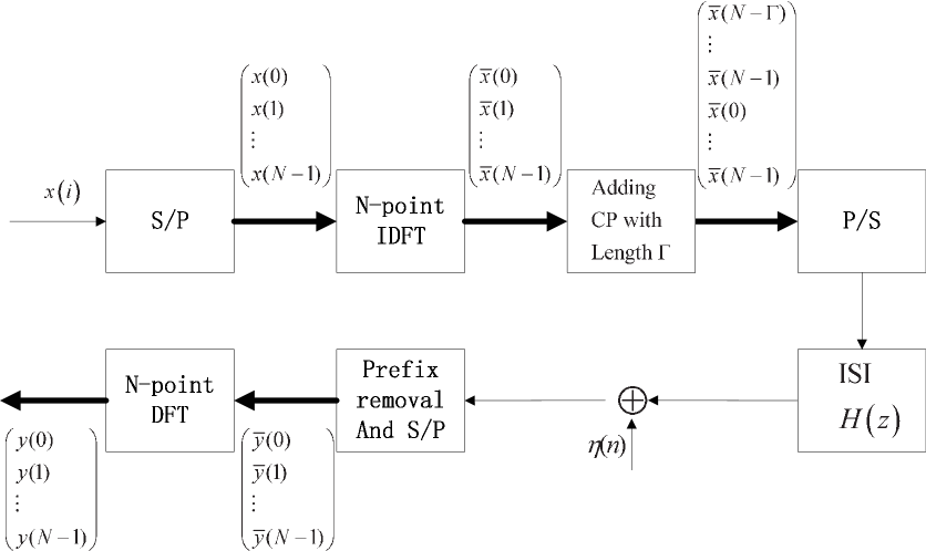
In this section, the conventional OFDM, and the V-OFDM system for single transmit antenna [3, 4] are briefly reviewed. The conventional OFDM system is shown in Fig. 1. is the frequency domain signal, is the number of the subcarriers in the OFDM system, and is the cyclic prefix length. After IDFT, the transmitted signal in time domain is
| (1) |
and then the transmitted signal with CP is
| (2) |
Assume that the ISI channel disperse has the following transfer function:
| (3) |
and
| h | ||||
| (4) |
is the corresponding channel impulse response (CIR) in time domain. At the receiver, CP is removed first, and we get
| (5) |
Then, transfer the received signal to frequency domain by DFT with size , we obtain
| (6) |
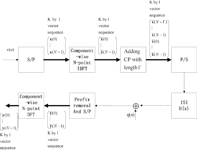
Fig. 2 illustrates the block diagram of the V-OFDM system. Data block is transmitted for each V-OFDM block, which contains vectors with symbols in each vector. (If we keep the block length unchanged, the block can be divided into small vectors with low PAPR and save CP, here we use as the block length). Let
| (7) |
where , and . V-OFDM does component-wise IDFT of size over the vectors, i.e.,
| (8) |
we have the signal in time domain as
| (9) |
Then, the transmitted symbol sequence after adding cyclic prefix (CP) in time domain can be written as
| (10) |
where , and . After removing the CP at the receiver, we have the signal in time domain as
| (11) |
where . With component-wise DFT in the similar way as (8), the signal will be transformed to frequency domain as
| (12) |
where . The relationship between the transmitted and received signals in z domain can be expressed as follows. From [4], assume that and are the th polyphase components of the z-transforms of the transmitted and received signals, respectively. Then, the received signal can be written in the following MIMO form in domain
| (13) |
where , , is the transform of the noise,
| (14) |
and
| (15) |
where
| (16) |
is the th polyphase component of (II) and (II) is the th polyphase component of (3). Note that, for the convenience later, we use length for the th polyphase component in time domain as well but its number of non-zero components is at most . It is clear that (II) has the same form as the conventional OFDM system (II) for each , while the channel length is at most as shown in (II).
III Proposed CDD-V-OFDM system
In this section, we first describe our proposed CDD-V-OFDM system and present some of its properties. We then present its performance analysis when the linear MMSE equalizer/receiver is used for every subchannel. Also, for convenience, in this section, we assume for some positive integer . A general case of can be similarly studied but the notations become more tedious.
III-A Proposed System Description
Combining V-OFDM with CDD transmission can enhance the diversity order and accommodate more antennas in the system, especially in massive MIMO system as we shall see in this section. Our proposed CDD-V-OFDM system is shown in Fig. 3. In this section, the CDD-V-OFDM system and its equivalent vectorized MIMO ISI CIR are presented, where a single receive antenna is used for convenience.
Assume the original data sequence as , which is blocked into vectors with symbols in each vector:
| (17) |
where and , . After the component-wise IDFT shown in (8), the signal in time domain is
| (18) |
where , and , . There are transmit antennas in this system and let us consider the th transmit antenna. The cyclic shift with amount in the th transmit antenna leads the signal in (18) to
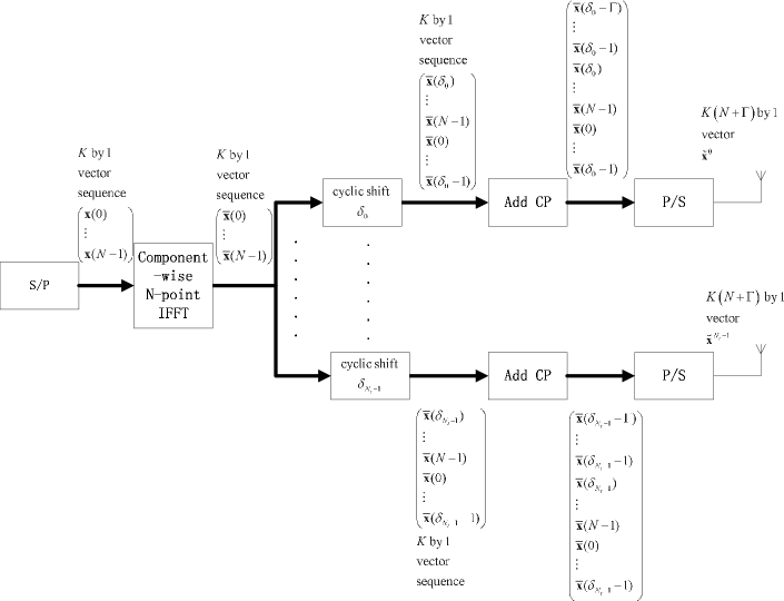
| (19) |
where
| (20) |
where . Then, the transmit signal after appending CP for the th transmit antenna is
| (21) |
where and . Consider the original CIR from the th antenna as
| (22) |
Then, the th polyphase of the received signal from the th antenna can be expressed as a linear convolution of and the original CIR from the th antenna as
| (23) |
Referring to the V-OFDM, we need to transform the linear convolution between the CIR and the transmit signals to the cyclic convolution between the vectorized ISI channel and the vectorized OFDM signals. Then, we do the same vectorization operation for the ISI channel as the V-OFDM signal. Assume that , and , for , we have and is
| (24) |
Then, the index of the signal in (III-A) is separated into two parts: one is the index of a symbol in a vector, i.e., , and the other is the index of the vector, i.e., . Substituting with , (III-A) is changed to
| (25) |
Consider the first equation in (III-A), the transmit signal consists of vectors with symbols in each vector. Thus, (25) is changed to
| (26) |
where and . Inside , , the region of CP is , which means, , for . After removing the CP at the receiver, the region is what we concern in the received signal. Here we divide the summation period of into two parts, and . Then, we have
| (27) |
Because , for , the second item of (26) is changed to
| (28) |
From (III-A) we know , for , then we have
| (29) |
Substituting with , we have
| (30) |
where . Then, the th polyphase component of the received signal can be expressed by the cyclic convolution of the vectorized OFDM signal and the vectorized ISI CIR as
| (31) |
where denotes modulo operation and . For the cyclic shift in (18) and (19), we have . Then, (III-A) is rewritten as
| (32) |
where, similar to (II), we have
| (33) |
Substituting with , and following the similar process as (III-A)-(III-A), for , we obtain
| (34) |
Since (III-A) is the signal from the th antenna, the overall received signal is the sum of the signals from all the antennas, which is
| (35) |
where
| (36) |
Equation (III-A) consists of polyphase components as . The equivalent SISO channel over all the polyphase components and all the antennas is
| (37) |
Then, the th polyphase component of length in is
| (38) |
Comparing (II) and (III-A), we can see that the equivalent ISI channel of the CDD-V-OFDM has the same form as that of V-OFDM for a SISO ISI channel, while in the CDD-V-OFDM system, the equivalent ISI channel is the sum of the cyclically shifted channels from different transmit antennas. Next, the vectorized ISI channel has the z-domain pseudocirculant matrix form as follows
| (39) |
where , , is the z-transform of (III-A), which is the th polyphase component of (III-A). From [21] and [26], the diversity order is closely related to the length of a non-overlapping multipath channel. To achieve the maximal spatial and multipath diversities, there should be no channel overlap between the CIRs from different antennas. Thus, the cyclic shift amount should meet the following condition, if ,
| (40) |
Then, the equivalent ISI SISO channel becomes
| (41) |
The equivalent ISI channel of the CDD-V-OFDM can also be regarded as an equivalent ISI channel in CDD-OFDM. The original CIR from the th antenna in CDD-OFDM system is the same as (III-A). Then, the overall equivalent ISI channel of the CDD-OFDM is
| (42) |
where . When the condition with holds, there are no overlaps between the CIRs from different antennas, and the equivalent ISI channel is
| (43) |
which has the same form as the equivalent ISI channel of CDD-V-OFDM (III-A).
Despite the similarities between the CDD-OFDM and CDD-V-OFDM systems, differences are obvious. Our CDD-V-OFDM system can accommodate as many as transmit antennas, while in the CDD-OFDM, the maximum number of antenna is in order to have that all cyclically shifted channel coefficients are not overlapped and thus achieve the full spatial and multipath diversities. Another difference between the CDD-V-OFDM and the CDD-OFDM systems is on cyclic delay shift. Here we give a proposition about the relationship between the cyclic shifts of the CDD-V-OFDM and CDD-OFDM systems.
Proposition 1.
Let be a signal in time domain. After cyclic shifts in OFDM and V-OFDM systems with shift amounts and , respectively, we get the cyclically shifted signals as , and , respectively, where , and . The two kinds of cyclic shifts have the same output signal, i.e., for any signal , if and only if .
Proof:
We first prove the sufficiency. In the cyclically shifted V-OFDM signal , we consider the th symbol of the th polyphase
| (44) |
which is the th symbol of the cyclically shifted OFDM signal . The sufficiency is proved. We next prove the necessity. When holds. For any , consider the th symbols of and , we know that . Furthermore, and are as follows,
| (45) |
Then, the equation holds for all the input signal . This implies that . ∎
We next show an example on how the equivalent ISI channel changes in the CDD-V-OFDM system. Suppose , , , and . The original CIR from the two transmit antennas are
| (46) | |||||
| (47) |
The blocked vector channels for the first antenna are
| (48) | |||||
| (49) |
and the corresponding z-domain matrix is
| (50) |
where
| (51) | |||||
| (52) |
For the second antenna, after the cyclic shift with amount , we have
| (53) | |||||
| (54) |
The corresponding z-domain matrix is
| (55) |
where
| (56) | |||||
| (57) |
Then, the th and the th polyphase components of the equivalent channel are the sum of the cyclically shifted channels from the two transmit antennas, which are
| (58) | |||||
| (59) |
respectively. Because we make a cyclic shift for the V-OFDM signal with amount , the original channel will be equivalently shifted with amount , and we can obtain the equivalent ISI SISO channel as
| (60) |
which will be the same as the equivalent ISI channel of the CDD-OFDM of the two transmit antennas with cyclic shift amount . The equivalent z-domain pseudocirculant matrix for the V-OFDM is
| (61) |
where the th and the th polyphase components of the equivalent channel in z-domain are
| (62) | ||||
| (63) |
respectively.
Let us see an example of the capability of accommodating antennas in the CDD-V-OFDM scheme in LTE system. Let the DFT size be , channel length be , CP length be , the number of the transmit antennas be . The multipath fading channel from the th transmit antenna is
| (64) |
In CDD-OFDM system, with cyclic shift amount 16 for each from the second antenna, the equivalent ISI channel will be
| (65) |
which has the size of . From the equivalent ISI channel, it is obvious that the multipath diversity can be fully obtained, while only transmit antennas are included in CDD-OFDM system, and the full diversity order is .
In our proposed CDD-V-OFDM, we take as an example, the CP length of the V-OFDM is 8. The blocked vector channel can be written as
| (66) |
which has length . Then, the OFDM signal space with DFT size can accommodate as many as transmit antennas to achieve the full spatial and multipath diversities of total order . The th polyphase component of the equivalent ISI channel is
| (67) |
The corresponding equivalent ISI channel has the size of , which is
| (68) |
When , the number of the accommodating antennas in the CDD-V-OFDM is times that of the CDD-OFDM.
III-B Symbol-by-Symbol Detection in Each Sub-carrier After the MMSE Equalization
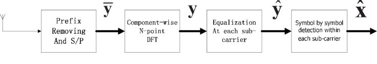
As it was mentioned earlier, V-OFDM converts an ISI channel to multiple constant MIMO subchannels and each constant MIMO subchannel includes information symbols that are ISI together by the constant MIMO channel matrix. Its ML decoding is, thus, the symbol joint ML decoding and may have a high complexity when is not small. In this subsection, we apply the MMSE equalizer/receiver for each of these constant MIMO subchannels for the CDD-V-OFDM system and the give the detection rule. The receiver of the CDD-V-OFDM system is shown in Fig. 4. The signal after removing the CP and serial-to-parallel transformation is
| (69) |
where . Take component-wise DFT transformation in the similar way as (8), we have the signal in frequency domain as
| (70) |
where . Then, the relationship between the received signal and the transmitted signal in frequency domain is
| (71) |
where is the equivalent noise in the frequency domain, and the equivalent channel matrix for the th sub-carrier is
| (72) |
where is a unitary matrix with entry at th row and th column as
| (73) |
where . The in (72) is a diagonal matrix as
| (74) |
where
| (75) |
With the frequency domain equivalent , we have the MMSE equalizer for the th sub-carrier as
| (76) |
The signal after equalization is
| (77) |
where
| (78) |
and . Then, the detection is processed symbol by symbol, which is
| (79) |
where is all the possible signal for and
| (80) |
Then the estimated signal is
| (81) |
where . The detection computational complexity is only linear proportional to the vector length and the DFT size .
III-C Performance Analysis
In this sucsection, based the detection rule (80) and the MMSE equalization in frequency domain, we analyze the diversity order of the CDD-V-OFDM system. Based on the derivation in Seciton \@slowromancapiii@.B, we directly apply the results obtained in [26] to get the diversity order.
Assume that the CIRs from different antennas are known at the receiver and the condition (40) holds for the cyclic shift amounts. Let be the transmission data rate, be the length of the CIR from a single transmit antenna, be the number of the transmit antennas and be the vector length of the signals in the CDD-V-OFDM system. Then, following [26], the diversity order of the CDD-V-OFDM system is
| (82) |
Remarks:
-
•
When holds, the diversity order of the CDD-V-OFDM is determined by . Under this condition, if decreases or increases, we can obtain a higher diversity order.
-
•
When holds, the diversity order of the CDD-V-OFDM is determined by . Increasing the number of transmit antennas can improve the diversity order of the CDD-V-OFDM system.
-
•
The V-OFDM system is the special case of the CDD-V-OFDM system when . Thus, the diversity order of the V-OFDM is
(83) From (82) and (83), we know that the the CDD-V-OFDM system has the same diversity order as the V-OFDM when . But the diversity order of the V-OFDM system can not be improved when , while the proposed CDD-V-OFDM can improve the diversity order by increasing the number of the transmit antennas.
-
•
The CDD-OFDM is also the special case of the CDD-V-OFDM when . The diversity gain can not be fully obtained unless the error correction coding is used over all the subcarriers, which can be seen from the simulation results. To achieve the maximal spatial and multipath diversities, the maximum number of accommodating antennas in the CDD-OFDM system is , while in the CDD-V-OFDM system, higher diversity order is obtained with the maximum number of the transmit antennas as . Furthermore, the CP length of each polyphase in the CDD-V-OFDM, i.e., , is only that of the CDD-OFDM, i.e., .
IV Simulation Results
In this section, we present some simulation results for the symbol error rate (SER) performance to show the diversity orders of the CDD-V-OFDM systems. Since the CDD-V-OFDM system contains multiple transmit antennas, we let the sum power of all the transmit antennas of the CDD-V-OFDM be . Then, we analyze the diversity orders of the systems under the condition . In all the simulations, the fading channel is i.i.d. complex Gaussian distributed with zero mean and unit variance. For all the figures, the systems are uncoded. The cyclic prefix length is chosen as for the CDD-V-OFDM system.
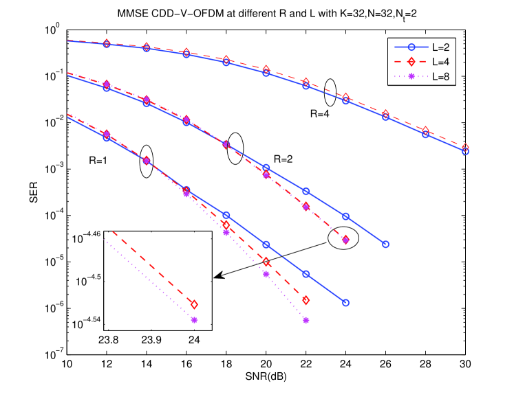
Fig. 4 shows the SER performance of the MMSE CDD-V-OFDM system at different and with , and . For the case , , and increasing from to , always holds. Then, the diversity order is always , which can be seen from the slopes of the curves. In the case , , and the condition still holds, then the diversity order of the CDD-V-OFDM is . When and , the condition holds again, and the corresponding diversity order is . In the case , . When , , respectively, the condition holds, and the diversity order of the CDD-V-OFDM is , respectively. This shows that under the condition , the diversity order of the CDD-V-OFDM system increases along the increase of . Fig. 4 also shows that under the condition , the diversity order of the CDD-V-OFDM system increases along the decrease of . From to and , , and the condition always holds. Then the diversity order of the system increases from to and , respectively. This result is shown in Fig. 4, which matches the result (82).
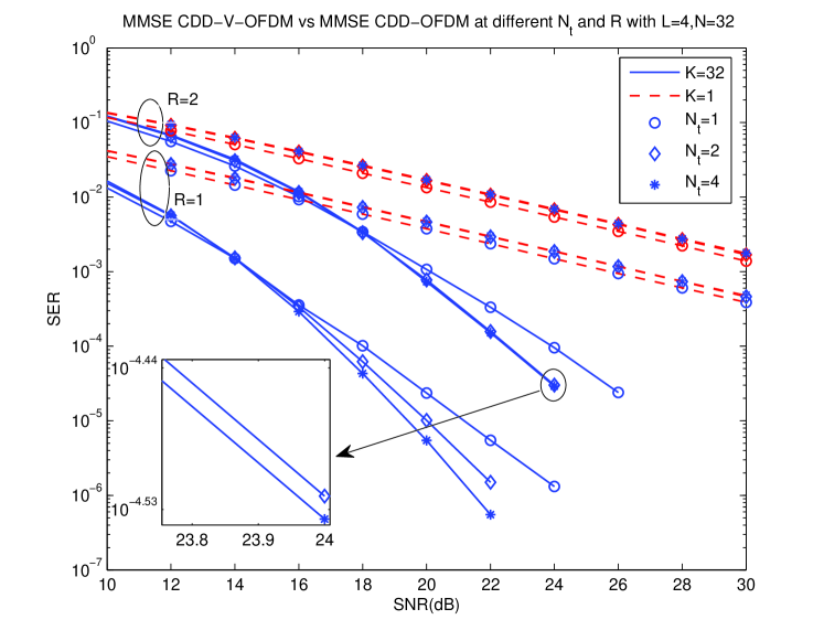
Fig. 5 shows the SER performance of the MMSE CDD-V-OFDM at different and with and . In Fig. 5, the special case is also shown, which is the CDD-OFDM system. For the CDD-OFDM system, the diversity order is always , whenever increases from to and . The maximum number of transmit antennas in the CDD-OFDM system is . The CDD-V-OFDM system always obtains higher diversity order than the CDD-OFDM. When , . When , and , . In the case , when increases from to and , , , and , respectively.
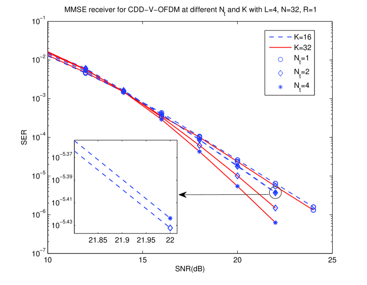
In Fig. 6, the SER performance of the MMSE CDD-V-OFDM system is presented at different and with and , . In the case of , when the number of the transmit antennas increases from to , the diversity order is increased from to . When , the condition holds, and then the diversity order is also . In the case , the condition always holds, then , the diversity of the system increases from to and along , respectively. Fig. 6 verifies that the increase of can improve the diversity order of the system.
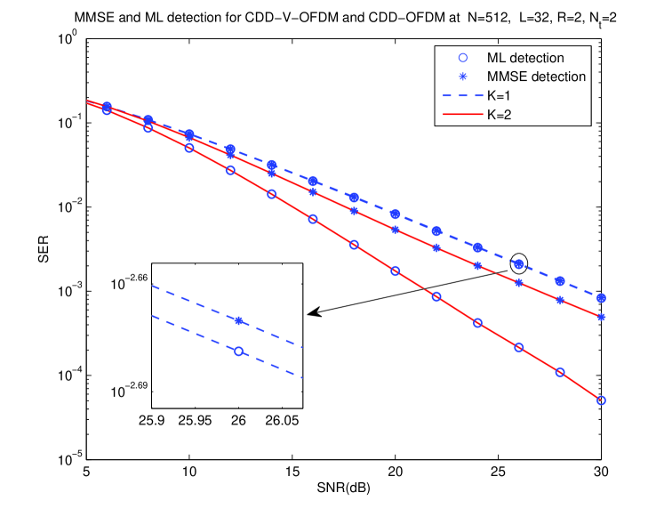
In Fig.7, , , and . Due to the complexity of ML detection, it is not easy to simulate for the cases with large and thus small and are simulated. In this case, the condition always holds. Then, . In comparison with the special case , i.e., the CDD-OFDM system, it is obvious that the CDD-V-OFDM has better performance.
V Conclusion
In this paper, we have proposed a CDD transmission for the single antenna V-OFDM system when there are multiple transmit antennas. With our proposed CDD-V-OFDM system, times more transmit antennas can be accommodated than the conventional CDD-OFDM system to collect both spatial and multipath diversities, which will become more interesting for a massive MIMO system, where is the vector size in V-OFDM. With the MMSE linear receiver applied to each subchannel, by following the previous result in [26] for a V-OFDM system, we have obtained the diversity order for our proposed CDD-V-OFDM system: , where is the transmission rate, is the number of transmit antennas, and is the ISI channel length from a transmit antenna to a receive antenna.
References
- [1] Evolved Universal Terrestrial Radio Access (E-UTRA), Physical Channels and Modulation, 3GPP TS 36.211, 2009.
- [2] IEEE Standard for Information Technology–Telecommunications and Information Exchange between Systems–Local and Metropolitan Area Networks–Specific Requirements–Part 11: Wireless LAN Medium Access Control (MAC) and Physical Layer (PHY) Specifications Amendment 6: Wireless Access in Vehicular Environments, IEEE 802.11 Working Group, 2007.
- [3] X.-G. Xia, “Precoded OFDM systems robust to spectral null channels and vector OFDM systems with reduced cyclic prefix length,” in IEEE International Conference on Communications (ICC’2000), New Orleans, USA. 2000, vol. 2, Jun. 2000, pp. 1110–1114.
- [4] ——, “Precoded and vector OFDM robust to channel spectral nulls and with reduced cyclic prefix length in single transmit antenna systems,” IEEE Trans. Commun., vol. 49, no. 8, pp. 1363–1374, Aug. 2001.
- [5] L. H. Grokop and D. Tse, “Diversity–multiplexing tradeoff in ISI channels,” IEEE Trans. Inf. Theory, vol. 55, no. 1, pp. 109–135, Jan. 2009.
- [6] A. Goldsmith, S. A. Jafar, N. Jindal, and S. Vishwanath, “Capacity limits of MIMO channels,” IEEE J. Sel. Areas Commun., vol. 21, no. 5, pp. 684–702, Jun. 2003.
- [7] K. R. Kumar, G. Caire, and A. L. Moustakas, “The diversity-multiplexing tradeoff of linear MIMO receivers,” Proc. IEEE Information Theory Workshop, ITW 07, Tahoe City, CA, pp. 487–492, Sept. 2007.
- [8] H. Bolcskei and A. J. Paulraj, “Space-frequency coded broadband OFDM systems,” in IEEE Wireless Communications Networking Conf., 2000., Chicago, IL, vol. 1, Sept. 2000, pp. 1–6.
- [9] W. Su, Z. Safar, M. Olfat, and K. R. Liu, “Obtaining full-diversity space-frequency codes from space-time codes via mapping,” IEEE Trans. Signal Processing., vol. 51, no. 11, pp. 2905–2916, Nov. 2003.
- [10] W. Zhang, X.-G. Xia, and K. B. Letaief, “Space-time/frequency coding for MIMO-OFDM in next generation broadband wireless systems,” IEEE Wireless Commun., vol. 14, no. 3, pp. 32–43, Jun. 2007.
- [11] W. Zhang, X.-G. Xia, and P.-C. Ching, “Full-diversity and fast ML decoding properties of general orthogonal space-time block codes for MIMO-OFDM systems,” IEEE Trans. Wireless Commun., vol. 6, no. 5, pp. 1647–1653, May. 2007.
- [12] A. Dammann and S. Kaiser, “Standard conformable antenna diversity techniques for OFDM and its application to the DVB-T system,” in Proc. IEEE Globecom, GLOBECOM’01., S. Antonio, Texas, vol. 5, Nov. 2001, pp. 3100–3105.
- [13] D. Gore, S. Sandhu, and A. Paulraj, “Delay diversity codes for frequency selective channels,” in IEEE International Conference on Communications (ICC’2002), New York, NY USA., vol. 3, Dec. 2002, pp. 1949–1953.
- [14] A. Dammann, R. Raulefs, and S. Kaiser, “Beamforming in combination with space-time diversity for broadband OFDM systems,” in IEEE International Conference on Communications (ICC’2002), New York, NY USA., vol. 1, Dec. 2002, pp. 165–171.
- [15] A. Dammann and S. Kaiser, “Low complex standard conformable antenna diversity techniques for OFDM systems and its application to the DVB-T system,” ITG FACHBERICHT, pp. 253–260, 2002.
- [16] ——, “Performance of low complex antenna diversity techniques for mobile OFDM systems,” in Multi-Carrier Spread-Spectrum & Related Topics. Springer, 2002, pp. 53–64.
- [17] M. Bossert, A. Huebner, F. Schuehlein, H. Haas, and E. Costa, “On cyclic delay diversity in OFDM based transmission schemes,” in OFDM workshop, vol. 2, 2002.
- [18] J. Tan and G. L. Stuber, “Multicarrier delay diversity modulation for MIMO systems,” IEEE Trans. Wireless Commun., vol. 3, no. 5, pp. 1756–1763, Sept. 2004.
- [19] A. Lodhi, F. Said, M. Dohler, and A. H. Aghvami, “Performance comparison of space-time block coded and cyclic delay diversity MC-CDMA systems,” IEEE Wireless Commun., vol. 12, no. 2, pp. 38–45, Apr. 2005.
- [20] G. Bauch and J. S. Malik, “Cyclic delay diversity with bit-interleaved coded modulation in orthogonal frequency division multiple access,” IEEE Trans. Wireless Commun., vol. 5, no. 8, pp. 2092–2100, Aug. 2006.
- [21] A. H. Mehana and A. Nosratinia, “Cyclic delay transmission achieves full diversity without (Pre) coding,” in IEEE International Conference on Communications (ICC’2012), Ottawa, ON. 2012, Jun. 2012, pp. 2375–2379.
- [22] H. Zhang, X.-G. Xia, L. J. Cimini, Jr., and P. C. Ching, “Synchronization techniques and guard-band-configuration scheme for single-antenna vector-OFDM systems,” IEEE Trans. Wireless Commun., vol. 4, no. 5, pp. 2454–2464, Nov. 2005.
- [23] H. Zhang and X.-G. Xia, “Iterative decoding and demodulation for single-antenna vector OFDM systems,” IEEE Trans. Veh. Technol., vol. 55, no. 4, pp. 1447–1454, Jul. 2006.
- [24] C. Han, T. Hashimoto, and N. Suehiro, “Constellation-rotated vector OFDM and its performance analysis over Rayleigh fading channels,” IEEE Trans. Commun., vol. 58, no. 3, pp. 828–838, Mar. 2010.
- [25] P. Cheng, M. Tao, Y. Xiao, and W. Zhang, “V-OFDM: On performance limits over multi-path Rayleigh fading channels,” IEEE Trans. Commun., vol. 59, no. 7, pp. 1878–1892, Jul. 2011.
- [26] Y. Li, I. Ngebani, X.-G. Xia, and A. Host-Madsen, “On performance of vector OFDM with linear receivers,” IEEE Trans. Signal Process., vol. 60, no. 10, pp. 5268–5280, Oct. 2012.