New examples of three-dimensional dilational materials
Abstract
Two-dimensional dilational materials, for which the only easy mode of deformation is a dilation are reviewed and connections are drawn between models previously proposed in the literature. Some models which appear to be dilational materials, but which in fact are not, are also discussed. Finally, four new examples of three-dimensional dilational materials are given.
Keywords: auxetics, dilational material, negative Poisson’s ratio
1 Introduction
Auxetic materials are (possibly anisotropic) materials with negative Poisson’s ratios and have attracted considerable attention: see the review of [7], the papers in this volume of Physica Status Solidi B, and references therein. A dilational material is an auxetic material for which a dilation is the only easy mode of deformation under finite deformations, and as a consequence they prefer to keep their shape (but not size) as they are deformed. Ideal dilational materials are rigid against all other deformations, or if flexible to other deformations then dilations cost no energy. This requires either sliding surfaces or ideal hinge type junctions, which however can approximated. In materials that are approximations to the ideal, dilations cost little energy by comparison to deformations that are not close to dilations. Ideal dilational materials, if flexible, are not necessarily elastically isotropic, but they have a Poisson’s ratio of in all directions over a range of strains. For example under infinitesimal deformations such a material with cubic symmetry could have a bulk modulus which is zero but two different shear moduli (the idealization of the material constructed by Bückmann et.al. [3] falls into this category).
The first example of a two or three dimensional dilational material appears to be the telescoping rod model of Rothenburg, Berlin and Bathurst [16], the simplest realization of which is shown in figure 1a, (see also figure 3 in [11] and figure 3a in [10]). The telescoping rods have sliding surfaces, and so in any realization of this material there would be frictional forces and the possibilty of sticking. If the microstructure is scaled to a very small size, and the telescoping rods reduced in proportion, then the total frictional surface area per unit volume will become very large, and friction will be an important consideration. Alternatively, in three dimensions (but not in two dimensions) the frictional area can be reduced by scaling the telescope diameter to be much smaller than its length, as its length is reduced. However, in this case, bending of the telescopes will have to be taken into account. An early model, with sliding surfaces, having a Poisson’s ratio of for infinitesimal deformations, was constructed by Almgren [1], but it is not a dilational material as it has an anisotropic response at large deformations. A dilational material without sliding surfaces was constructed by Milton [11], see figure 5 in that paper, and appears to be the first model with a negative Poisson’s ratio having chirality. Related to this chiral linkage model (see figure 2) is an elegant structure (composed of rotating hexagons and triangles) discovered by Mitschke et.al. [14]: see also [13].
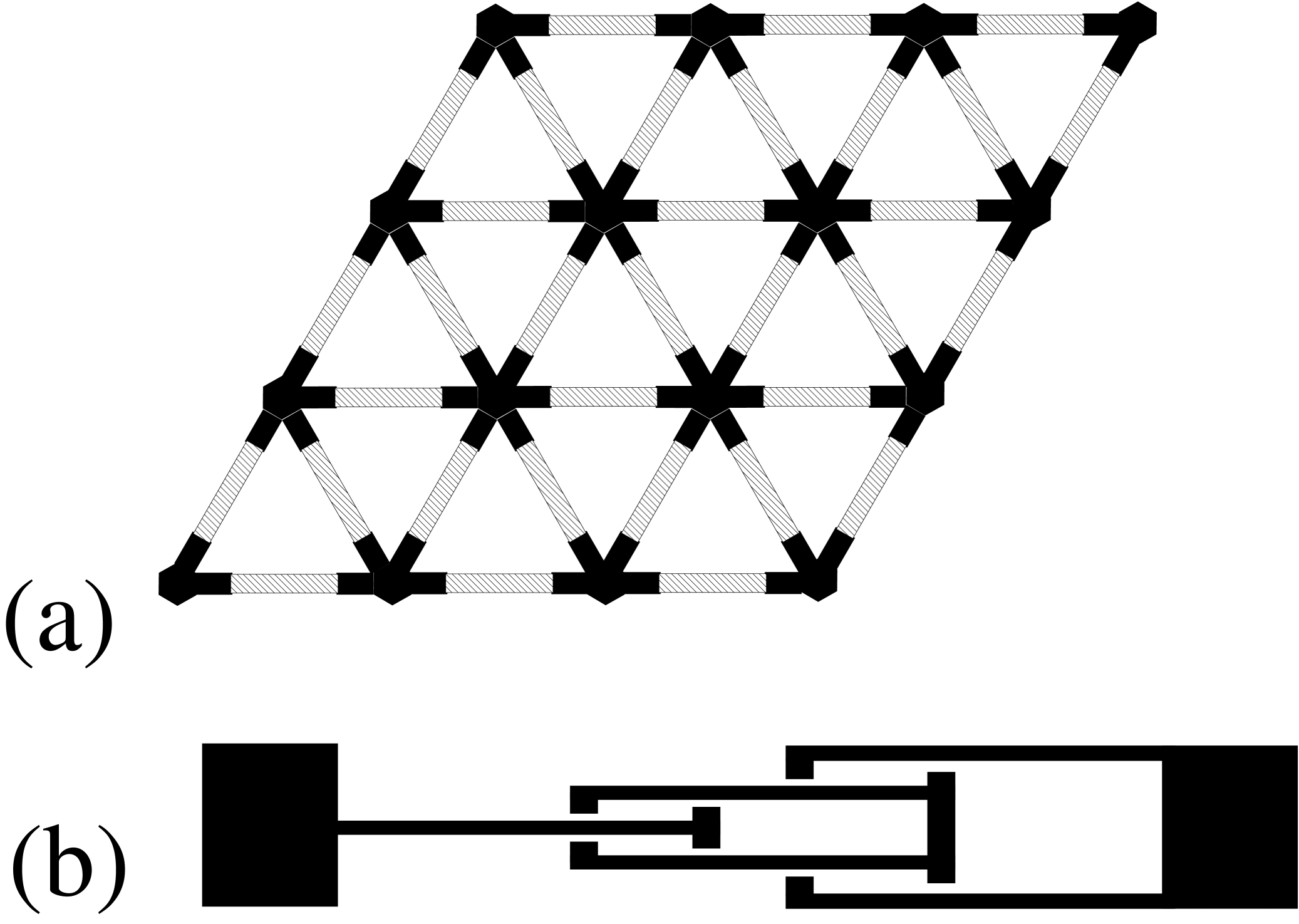

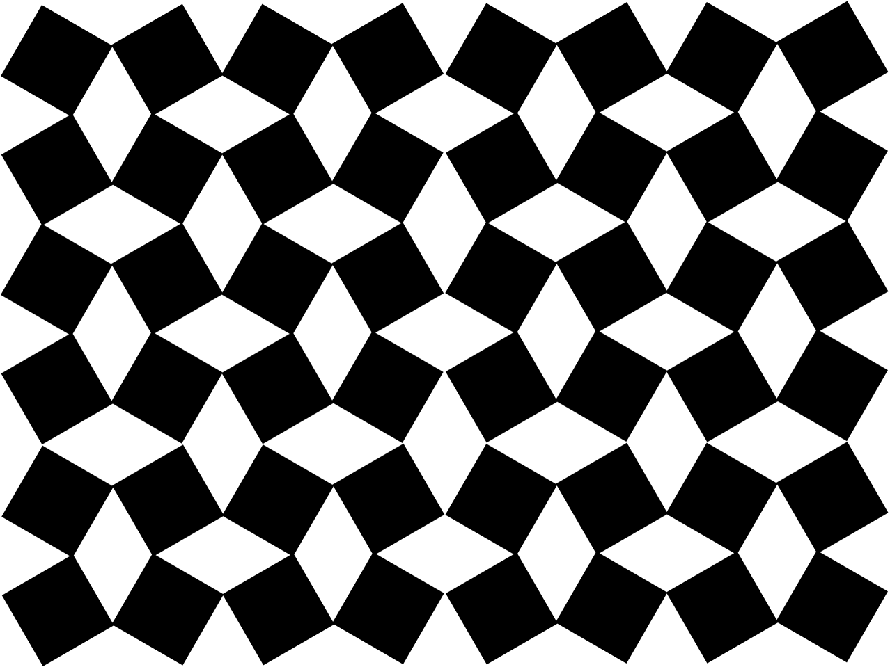
Another especially simple dilational material is the rotating squares model of Grima and Evans [8] (see figure 3) that is a simplification of an earlier model of Sigmund [17] (see his figure 4) which was recently rediscovered and generalized by Cabras and Brun [4]. Sigmund [17] obtained dilational materials built from rotatable frames in both two and three dimensions, but these have sliding surfaces. Dilational materials can also exhibit arbitarily large flexibility windows even without using sliding surfaces (such as telescoping rods with multiple sheaths as in figure 1b): see the unit cell in figure 8 in [12]. A three-dimensional rotating cuboid structure was constructed by Attard and Grima [2], which exhibits auxetic but not dilational behavior.
Recently, three dimensional dilational materials without sliding surfaces have been discovered (see the unit cell in figure 19b of [12], and [3]). In particular the model in [3] was investigated in detail, and moreover experimentally realized and tested, exhibiting a Poisson’s ratio as low as . Previously polymer foams had been found to have Poisson’s ratio values below maintained over about strain [6], and in metal foams a Poisson’s ratio of had been achieved [5], although it is not clear if these non-periodic foam structures would permit a Poisson’s ratio approaching , if suitably manufactured.
This paper develops four additional examples of three-dimensional dilational materials without sliding surfaces. The ideal dilational materials discussed here which do not have sliding surfaces incorporate hinges. These hinges can be appoximated in various ways without the use of sliding surfaces as illustrated in figure 4. The models presented here show the variety of ways dilational materials can be designed, and could serve as blueprints for the physical construction of realistic materials which are close to being dilational.

2 Models which are not dilational materials
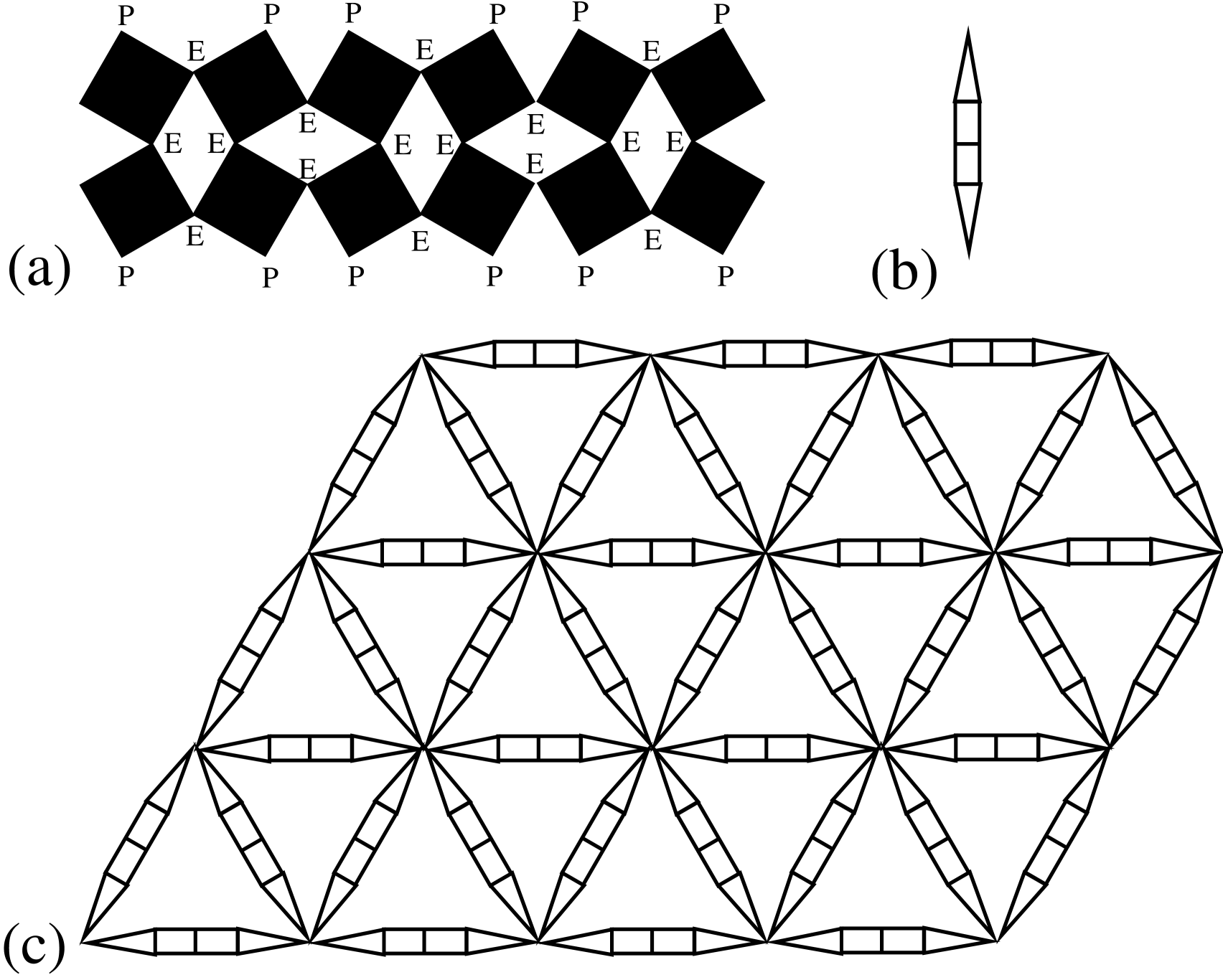
Some models which at first sight appear to be dilational materials, turn out not to be upon closer investigation. An example is the chiral honeycomb of Prall and Lakes [15] as shown in figure 5a. As recognised by them, deformation of this honeycomb under finite dilation requires some energy, due to the bending of the ribs as in figure 5b. Suppose we have a beam of such material, cells wide and cells long which we clamp in the middle between two lubricated rectangular blocks as in figure 5c. The question is whether the deformation will be one of uniform dilation, costing an energy per unit cell that is a total energy of , or whether the deformation will be closer to that illustrated in figure 5c. To show that it is not a uniform deformation it suffices to obtain a trial deformation field with lower energy. To do so we choose a trial field where the deformation is zero outside a transition region, and inside the transition region which is cells wide is allowed to deform in some way (independent of ) compatible with the boundary conditions at the clamps. Let be the total energy of the trial deformation, which is independent of . Then if is such that the prefered deformation will not be one of uniform dilation. Note that as the thickness of ribs approaches zero, while the moduli of the ribs are appropriately rescaled, the energies and will approach fixed limits: thus the prefered deformation will not be one of uniform dilation even in the limit as the ribs are infinitesimally thin. The crucial point is that the width of the actual transition region remains almost independent of and almost independent of the thinness of the ribs, for sufficiently large and for sufficiently thin ribs. By contrast if we did the same experiment with approximations to the dilational materials discussed here (with hinges of the type described in figures 4(b), 4(c) and 4(d)) the width of the actual transition region would continue to increase as the approximation to the ideal material improves so that ultimately the beam would undergo approximately uniform dilation for fixed no matter how large is. The difference is that in the approximations to the dilational material, the energy required to splay (taper) the material is enormously larger than the energy to uniformly compress it, with the ratio approaching infinity as the material becomes more ideal. This is not true of the chiral honeycomb: when the chiral honeycomb is splayed it is only necessary that the ribs be bent a little more than under compression. Nevertheless, it may be the case that the chiral honeycomb model can be modified to obtain a dilational material (perhaps by tapering the endpoints of the ribs down to points meeting the circles at an angle, rather than tangentially, and appropriately rescaling the moduli.)

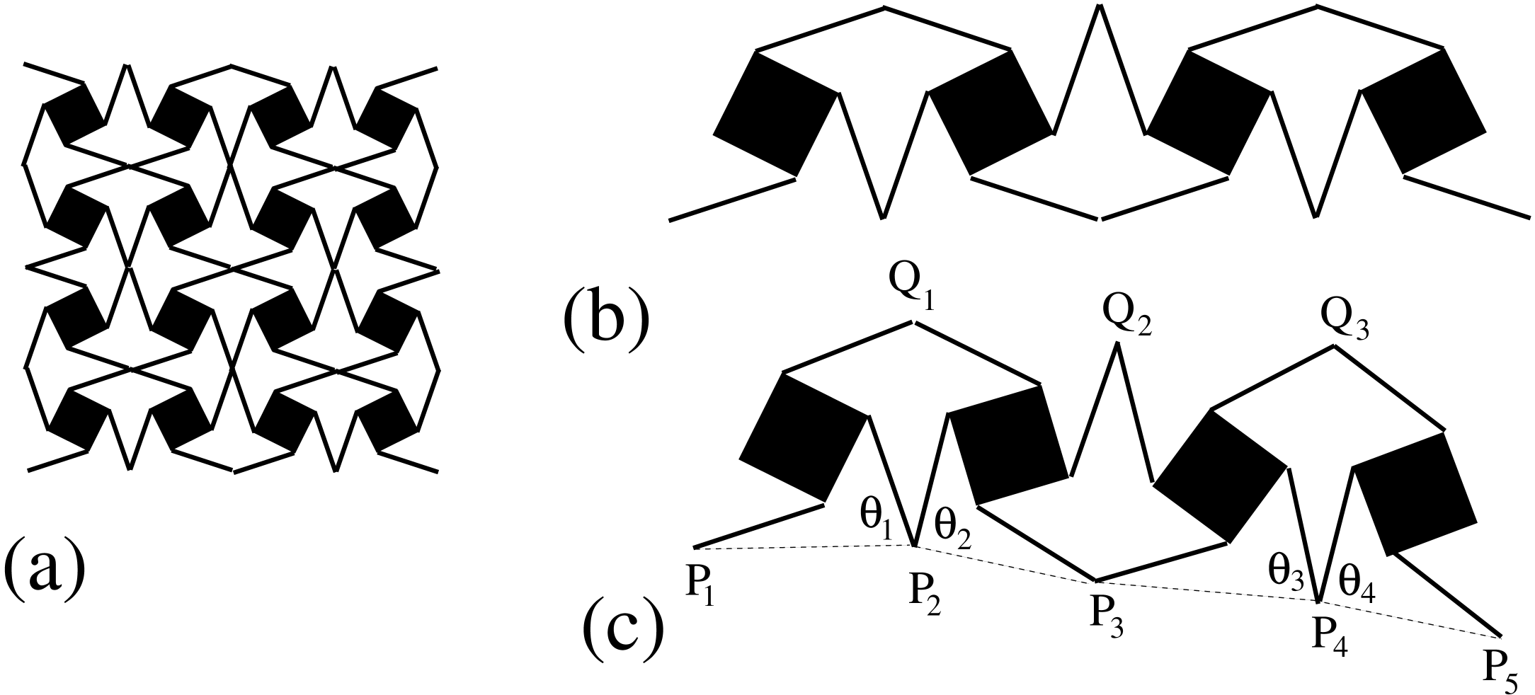
Another model which is not a dilational material is the two-dimensional variant of the three-dimensional model proposed in [3]. This variant illustrated in figure 6a, has macroscopic easy deformations which are non-affine. To understand this, take one row of the model as in figure 6b, and consider its deformations as in figure 6c. Within limited ranges the position of the points , can be chosen independently as can be the angles , . Taken together they (and the geometry) determine the position of the points , at the top of this row. The next row can be joined to these points, and so on, leaving a lot of internal parameters (the angles , in each row) that can be freely varied (within limits), and which (along with the positions of the points , of the first row) determine the possible macroscopic deformations of the structure. (It may be necessary to assume the structure has bounded extent). This argument does not apply to the three dimensional dilational material proposed in [3] since the orthogonality of the panels in that construction guarantees that the macroscopic easy deformation will be affine, and necessarily a dilation.
3 New three-dimensional dilational materials
Rothenburg, Berlin and Bathurst [16] recognized that their telescoping rod model, our figure 1, extends to three dimensions. They suggested taking a random, statistically homogeneous and isotropic network of trusses and replacing the trusses by telescoping rods bolted at fixed angles at the junctions. Alternatively one could put telescoping rods replacing the nearest neighbour bonds in a face centered cubic lattice, as suggested by Lakes and Wojciechowski [10], or in a hexagonal close packed lattice, with the ends of the rods welded at the vertices. Replacing the nearest neighbour bonds by telescoping rods in some other lattices such as the cubic or hexagonal lattice will not work as these lattices allow some easy modes of deformations in addition to dilations. If one wishes to avoid sliding surfaces in each telescoping rod, one way of doing this is to use rods which have Sarrus linkages (figure 7) in their center. This is an especially easy way to obtain three-dimensional dilational materials. Interestingly the Sarrus linkage appears in the rotating cuboid structure of Attard and Grima [2], which exhibits auxetic (but not dilational) properties.

The three-dimensional rotating squares model of Sigmund [17] is easily modified to avoid sliding surfaces if the rotating square plates on each face of the unit cube are curved (with positive curvature) so they no longer slide against each other, as sketched in figure 8.

The rotating squares model of Grima and Evans [8] (see our figure 3) can also be used as a basis for constructing three-dimensional dilational materials. as illustrated in figure 9. In any horizontal plane going through a vertex in the model of figure 9c the cross sectional structure will look exactly like the rotating squares model, and thus the macroscopic deformation in this plane must be one of uniform dilation. The same can be said for the cross sectional structure in any plane at or going through a vertex in the model of figure 9c. Since the points are shared by the planes the same dilational factor must be common to each plane. Thus the three-dimensional macroscopic deformation must be one of uniform dilation.
Motivated by the three-dimensional dilational material, with the cubic unit cell in figure 19b of [12], which has as its faces square panels the vertices of which remain square as the material deforms, one can similarly consider equilateral triangular panels as in figure 10, which remain equilateral as the panel deforms. These panels could be joined together to form regular octohedra (8 panels for each octahedron), and the octohedra stacked with tetrahedral cavities in-between to form a tetrahedral-octahedral honeycomb, which will then be yet another three-dimensional dilational material.

Acknowledgements
GWM is grateful to Martin Wegener and his group for stimulating this research and to the referees and Roderic Lakes for helpful comments on the manuscript. Additionally GWM is thankful for support from the National Science Foundation through grant DMS-1211359.
References
- [1] R. F. Almgren, An isotropic three-dimensional structure with Poisson’s ratio , Journal of Elasticity, 15 (1985), pp. 427–430.
- [2] D. Attard and J. N. Grima, A three-dimensional rotating rigid units network exhibiting negative Poisson’s ratios, Physica Status Solidi. B, basic solid state physics, 249 (2012), p. 1330–1338.
- [3] T. Bückmann, R. Schittny, M. Thiel, M. Kadic, G. W. Milton, and M. Wegener, On three-dimensional dilational elastic metamaterials, New Journal of Physics, 16 (2014), p. 033032.
- [4] L. Cabras and M. Brun, Auxetic two-dimensional lattices with Poisson’s ratio arbitrarily close to , Proc. R. Soc. A, 470 (2014), p. 20140538.
- [5] J. B. Choi and R. S. Lakes, Non-linear properties of metallic cellular materials with a negative Poisson’s ratio, Journal of Materials Science, 27 (1992), pp. 5375–5381.
- [6] , Non-linear properties of polymer cellular materials with a negative Poisson’s ratio, Journal of Materials Science, 27 (1992), pp. 4678–4684.
- [7] G. N. Greaves, A. L. Greer, R. Lakes, and T. Rouxel, Poisson’s ratio and modern materials, Nature Materials, 10 (2011), pp. 823–837.
- [8] J. N. Grima and K. E. Evans, Auxetic behaviour from rotating squares, Journal of Materials Science Letters, 19 (2000), pp. 1563–1565.
- [9] M. Kadic, T. Bückmann, N. Stenger, M. Thiel, and M. Wegener, On the practicability of pentamode mechanical metamaterials, Applied Physics Letters, 100 (2012), p. 191901.
- [10] R. S. Lakes and K. W. Wojciechowski, Negative compressibility, negative Poisson’s ratio, and stability, Physica Status Solidi. B, basic solid state physics, 245 (2008), pp. 545–551.
- [11] G. W. Milton, Composite materials with Poisson’s ratios close to , Journal of the Mechanics and Physics of Solids, 40 (1992), pp. 1105–1137.
- [12] , Complete characterization of the macroscopic deformations of periodic unimode metamaterials of rigid bars and pivots, Journal of the Mechanics and Physics of Solids, 61 (2013), pp. 1561–1568.
- [13] H. Mitschke, G. E. Schröder-Turk, K. Mecke, P. W. Fowler, and S. D. Guest, Symmetry detection of auxetic behaviour in 2D frameworks, EPL (Europhysics Letters), 102 (2013), p. 66005.
- [14] H. Mitschke, J. Schwerdtfeger, F. Schury, M. Stingl, C. Körner, R. F. Singer, V. Robins, K. Mecke, and G. E. Schröder-Turk, Finding auxetic frameworks in periodic tessellations, Advanced Materials, 23 (2011), pp. 2669–2674.
- [15] D. Prall and R. S. Lakes, Properties of a chiral honeycomb with a Poisson’s ratio , International Journal of Mechanical Sciences, 39 (1996), pp. 305–314.
- [16] L. Rothenburg, A. A. Berlin, and R. J. Bathurst, Microstructure of isotropic materials with negative poisson’s ratio, Nature, 354 (1991), pp. 470–472.
- [17] O. Sigmund, Tailoring materials with prescribed elastic properties, Mechanics of Materials: An International Journal, 20 (1995), pp. 351–368.