BEAM–BEAM STUDY OF ERL BASED eRHIC
Abstract
Beam–beam effects in eRHIC, the proposed ERL-based Electron–Ion Collider (EIC) at BNL, have several unique features distinguishing them from those in hadron-colliders and lepton-colliders. Taking the advantage of the fact that the electron beam is used only once, we expect the luminosity to be 10 times greater than for the ring–ring collision scheme with similar parameters. However, without instituting proper treatments, the quality of electron and hadron beams can undergo degradation or even beam loss, driven by the beam–beam interactions. We will discuss the harmful effects, including the disruption and mismatch effect of the electron beam, the kink instability and the noise heating of the ion beam and the possible countermeasures.
1 Introduction
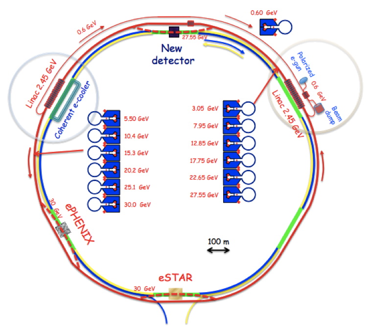
The main advantage of an energy recovery linac (ERL) based electron–ion collider (EIC) compared with a ring–ring collider is the higher achievable luminosity of the former. In an ERL-based EIC, which we also call a linac-ring scheme, the electron bunch collides only once with the ion bunch and thereafter is recycled. Hence, the beam–beam parameter for the electrons in ERL scheme can exceed by a large margin (as in Table 1) that permissible for electron circulating in a ring. While the beam–beam parameter for the ions remains the same in both schemes, the luminosity achieved in the linac-ring collision scheme exceeds that of the ring–ring collider scheme between 10 and 100 times [1]. Figure 1 illustrates the layout of eRHIC, the EIC proposed in Brookhaven National Laboratory. Table 1 lists its design parameters.
In the new parameter range of eRHIC, the electron beam is subject to a very strong beam–beam effects that create a new set of beam dynamics effects. First, the electron beam experiences significant disruption and mismatch effects due to the beam–beam interaction. Second, the collective motion of the electron beam inside the ion beam during their collision can cause a new head–tail type of instability, named ’kink instability’. And the ion beam can be heated up by the noise of the fresh electron beam each turn. In this paper, we will report our studies on those individual effects and carry out countermeasures to the harmful ones.
| Parameters | Range |
|---|---|
| Electron beam energy (GeV) | 5-30 |
| Ion beam energy (GeV) (proton) | 50-250 |
| Electron beam disruption parameter | 5-142 |
| Ion beam–beam parameter | 0.015 |
| Ion bunch length (cm) | 8.3 |
| Electron bunch length (cm) | 0.2-0.4 |
| Electron and ion (cm) | 5 |
| Ion synchrotron tune | 0.004 |
2 Electron disruption effects
The electron beam experiences very strong beam–beam force from the ion beam in the interaction region. The force will make the electron beam oscillate inside the ion beam and deform the distribution of the electron beam, as studied in [2]. We found that the disruption parameter is convenient to characterize the oscillation of the electron beam, where is the ion bunch length and is the focal length of the linearized beam–beam interaction. For an ion beam with Gaussian longitudinal distribution, the number of oscillations of the electron beam inside the ion beam is
Thus, for the eRHIC parameters, a single electron will oscillates up to 3 full oscillations in the ion beam.
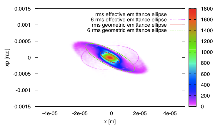
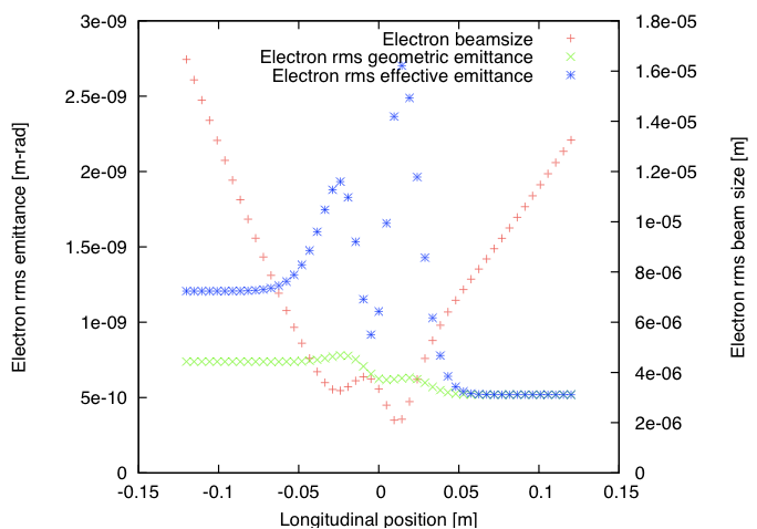
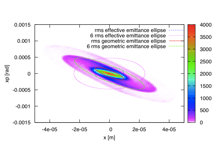
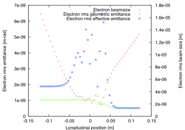
We use simulation code, EPIC [3], to calculate the electron beam evolution inside the opposing ion beam. Figure 2 and Fig. 3 illustrate the examples of the electron beam distribution after the collision and the e-beam evolution inside the ion beam. The former correspond to the case of , and latter for . In the electron beam distribution plots, the nonlinear force deform its initial Gaussian distribution completely. The electrons with larger betatron amplitude rotate slower than those in the core. Therefore the distribution after collision forms a spiral shape. We use 2 different definitions of beam emittance to characterize the occupied phase space area. One is the r.m.s. geometric emittance obtained from the beam distribution, written as
| (1) |
The other emittance uses the design optics function and is called effective emittance. It is defined as the half of the average value of the Courant–Snyder invariant of all macro-particles based on the design lattice
| (2) |
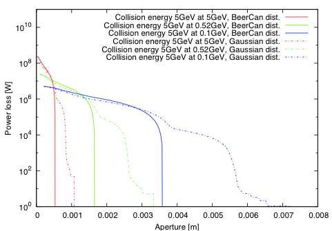
In the e-beam distribution plots of Fig. 2 and Fig. 3, both emittances are represented as ellipses of 1 r.m.s. value and 6 r.m.s. value. The evolution plots illustrate the evolution of the 2 r.m.s. emittance and the r.m.s. beam size. These plots clearly show the mismatch between the beam distribution and the design optics due to the beam–beam interaction. The effective emittance will determine the aperture requirement of the magnet downstream of interaction point (IP), as shown in Fig. 4. The calculated aperture shows that the small-gap magnet designed for eRHIC is suitable for the ERL energy recovery passes.
3 Kink instability and its mitigation methods
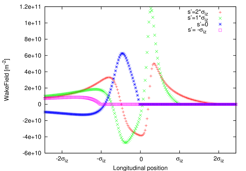
The kink instability develops due to the electron beam passes the imperfection of the head of the ion beam to its tail. Therefore, for the ion beam, the beam–beam interaction behaves as an effective wake field. If we assume both beams have only infinitesimal offsets, the wake field
| (3) |
can be retrieved from simulation, where is the number of ions in the slice, is the energy of the ion beam and is the classical radius of the ion beam. The wake field is illustrated in Fig. 5.
The threshold of the strong head–tail instability (the kink instability) can be calculated using the 2-particle model or the multi-particle model[4]. Both models are based on linearized beam–beam forces. For a 2-particle model, the threshold is simply: . However, to model the electron beam correctly in the high disruption parameter case, the multi-particle model should be used, predicting the threshold as in Fig. 6.
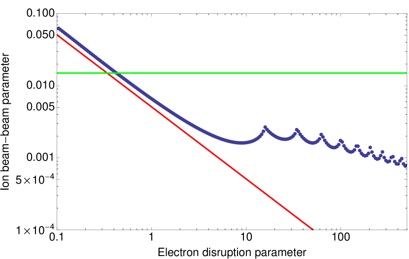
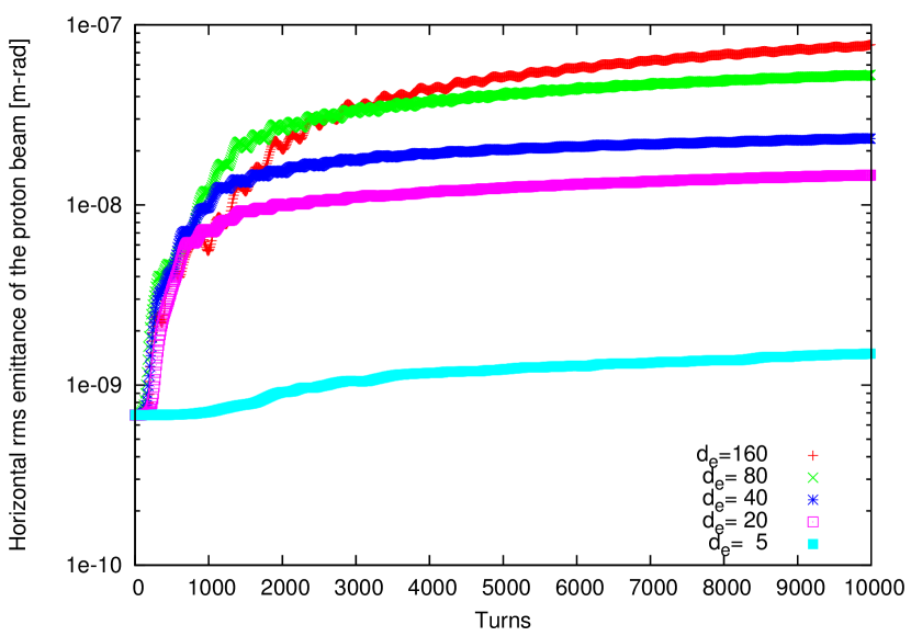
Both linear models predict that the parameter of the eRHIC exceeds the threshold. A simulation using nonlinear beam–beam forces is required to confirm this understanding. Figure 7 shows the emittance growth associated with the kink instability at different disruption parameters of the electron beam. Even with the lowest disruption parameter, , the system is not stable at +2 chromaticity (the nominal value of RHIC operation), although the emittance growth in this case is much less than those with higher . If we increase the chromaticity to stabilize the emittance growth, it requires unreasonable values. Therefore, a dedicate feedback system is desired as a countermeasure.
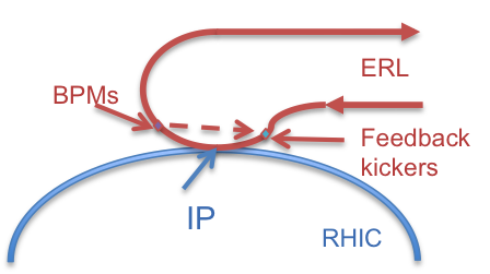
The first feedback system [4], shown in Fig. 8, takes full advantage of flexibility of a linac-ring scheme, which has the following procedures. We steer the fresh electron bunch before collision based on the transverse offset of the last-used electron bunch that collides with the same ion bunch. Then the centroid of the new electron bunch will oscillate within the opposing ion bunch due to the focusing beam–beam force. We are expecting that oscillation of the centroid of the electron bunch gives the ion bunch proper kicks to correct the offset of the ion bunch before the visible adverse effect, such as emittance growth and luminosity loss, due to the kink instability.
Mathematically, we introduce the offset by modifying the motion of the centroid of the electron bunch based on the information from the last one:
| (4) |
Here, the subscript denotes the electron–ion collision in turn, and the subscripts and respectively represent the bunch centroid before and after collision. Map defines the algorithm of the feedback system. Here, for simplicity and easier realization, we limit to be a matrix.
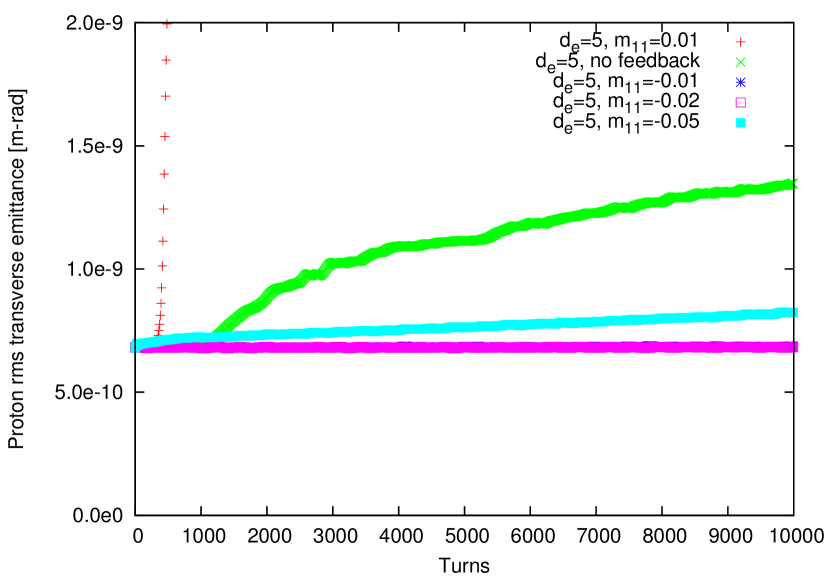
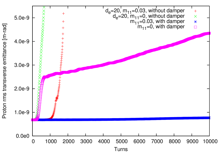
Figure 9 shows the effect of this feedback system at disruption parameter 5. In this case, the emittance growth due to the kink instability is suppressed with proper amplitude of the feedback gain (-0.01 or -0.02) without a noticeable decreasing in luminosity. An incorrect sign of the gain may boost the instability, as shown by the red dots in Fig. 9.
When the disruption parameter exceeds 15, this feedback system itself can not stabilize the emittance, because the system will excite the instability of the rigid mode while it can correct the head–tail mode of the ion beam. Therefore we have to add the transverse bunch-by-bunch damper to damp the rigid mode of the ion beam simultaneously. The result for , as an example, is shown in Fig. 10. The red dots show the case with the feedback gain of without transverse damper. The centroid of the ion bunch becomes unstable and causes fast emittance growth due to the offset of two beams. By applying the bunch-by-bunch feedback in the simulation, the ion centroid is stable and the emittance growth is prevented (blue curve).
The simple feedback loses its efficiency when . In this range, the electron beam oscillate too fast and the frequency of the oscillation does not match that of the lowest instability mode. We need an alternative feedback scheme for this disruption parameter range, such as a traditional pick-up and kicker system in the ion beam, to suppress the instability coherently [5].
For the pickup–kicker system, the effect can also be modelled as a wake field. If we assume the system has a uniform frequency response with low and high frequency limits and , the corresponding wake field of this system is [6]
| (5) |
where is related to gain of the amplifier between the pickup and the kicker.
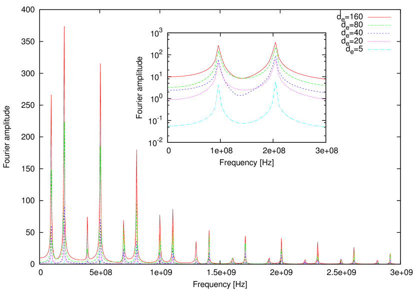
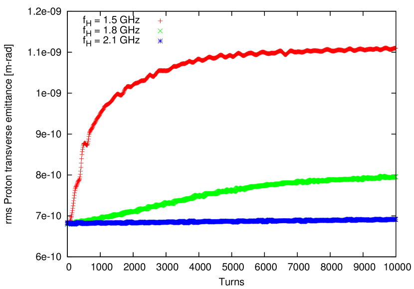
We fix the low frequency limit to 50 MHz, which is below the first peak in the bottom figure of Fig. 7. Then we vary the high frequency limit to find the requirement for the individual disruption parameter.
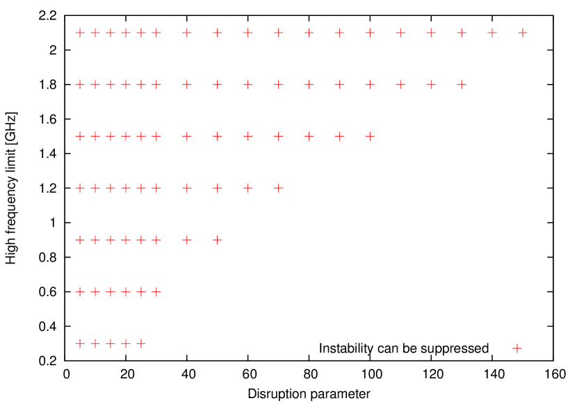
Figure 11 shows that the required is at least 2.1 GHz to suppress the kink instability when is 150. For other , as shown in Fig. 12, the required is a monotonically increasing function of . Therefore, we demonstrated that the kink instability will be suppressed by a pickup and kicker system with whole electron beam disruption parameter range (5–150), if the required frequency bandwidth is selected.
4 Noise heating effect of the ion beam
Since the ion beam always collides with fresh electron bunches, the electron beam parameter fluctuation will affect the ion beam through the beam–beam interaction. The fluctuations can be classified as two types. The first is dipole errors due to the electron beam transverse position offset; the second is quadrupole error due to the fluctuation of the electron beam intensity or transverse beam size.
If the noise of the electron beam is considered as white noise, i.e. a uniform spectrum in frequency domain, the effect of both dipole error and quadrupole errors can be evaluated analytically. For the quadrupole errors, the r.m.s. beam size of the ion beam is expected to grow exponentially, with the rising time
where is the beam–beam parameter of the ion beam, is the revolution period and is the r.m.s. error of the beam–beam focal length. For eRHIC parameters, to get a slow rising time (~10 hours), the relative error of the electron beam parameter should be better than . A Lorentz frequency spectrum is considered, where is a free parameter much less than 1 and is the angular revolution frequency of the ion ring. In this case, the rising time is lengthened to , where
For the dipole errors, the ion beam is kicked turn by turn due to the electron beam random offset. By following the well-known random walk formulas, the ion beam displacement gives and , where is the turn electron beam displacement at IP. We need a bunch-by-bunch transverse damper in the ion ring to compensate the dipole heating up effect.
5 Conclusion
We report on the key finding for distinct beam–beam effects in the ERL based eRHIC. Our study identified the challenges as well as possible countermeasures for both the electron and the ion beams.
A dedicated feedback system is required to suppress the emittance growth caused by the kink instability. We proposed two possible feedback systems. The feedback applied to the electron beam works for moderate values of the disruption parameter, e.g. . A traditional broad-band pickup and kicker feedback system can damp the instability for the whole range of the disruption parameter expected in eRHIC.
We report on the requirement for the intensity and beam size stability of the electron beam to avoid the hadron beam emittance growth caused by noise in beam–beam interactions. We also established a need for a transverse bunch-by-bunch damper to compensate for the possible heating effect caused by random noise in the transverse displacement in the electron beam.
References
- [1] V. Ptitsyn et al., eRHIC Accelerator Position Paper, Tech. Rep. (C-AD, BNL, 2007).
- [2] Y. Hao and V. Ptitsyn, Phys. Rev. ST Accel. Beams 13 (2010) 071003.
- [3] Y. Hao, Beam-Beam Interaction Study in ERL based eR- HIC, Ph.D. thesis, Indiana University, 2008.
- [4] Y. Hao, V. N. Litvinenko and V. Ptitsyn, Phys. Rev. ST Accel. and Beams 16 (2013) 101001.
- [5] Y. Hao et al., Kink Instability Suppression with Stochastic Cooling Pickup and Kicker, Proc. Int. Particle Accelerator Conf., New Orleans, NM, 2012.
- [6] M. Blaskiewicz and J.M. Brennan, WEM2105, Proc.COOL, Bad Kreuznach, 2007.