Microwave Coupling to ECR and Alternative Heating Methods
Abstract
The Electron Cyclotron Resonance Ion Source (ECRIS) is nowadays the most effective device that can feed particle accelerators in a continuous and reliable way, providing high-current beams of low- and medium-charge-state ions and relatively intense currents for highly charged ions. The ECRIS is an important tool for research with ion beams (in surface, atomic, and nuclear science) while, on the other hand, it implies plasma under extreme conditions and thus constitutes an object of scientific interest in itself. The fundamental aspect of the coupling between the electromagnetic wave and the plasma is hereinafter treated together with some variations to the classical ECR heating mechanism, with particular attention being paid to the frequency tuning effect and two-frequency heating. Considerations of electron and ion dynamics will be presented together with some recent observations connecting the beam shape with the frequency of the electromagnetic wave feeding the cavity. The future challenges of higher-charge states, high-charge breeding efficiency, and high absolute ionization efficiency also call for the exploration of new heating schemes and synergy between experiments and modelling. Some results concerning the investigation of innovative mechanisms of plasma ignition based on upper hybrid resonance will be described.
1 Introduction
The Electron Cyclotron Resonance Ion Source (ECRIS) is used to deliver beams of singly or multiply charged ions for a wide range of applications in many laboratories. In particular, such devices are well suited for the production of Highly Charged Ions (HCIs) – a key consideration for the new acceleration facilities (e.g. FAIR, RIA, HRIBF, etc.), which will require milliampere levels of HCIs. In order to get such high currents, the recent progress in the performance of the ECRIS has been mainly linked to improvement of the plasma magnetic confinement within the source chamber and to an increase of the frequency for the feeding microwaves which, under proper conditions, develop to higher plasma densities [1]. The trend followed until now has been to increase the frequency and the magnetic field, leading to rising costs for the technology and safety problems for the magnet’s cryostat because of the growth of hot electrons: the frequency and magnetic field scaling are close to saturation. Apart from this main route, various techniques are also employed to enhance the production of HCIs, such as the use of secondary emission materials, the wall coatings, the installation of a bias disc, or gas mixing, to mention the most important ones [2].
Moreover, in the past decade, some experiments involving new approaches to feeding have allowed an increase in the performance of the conventional ECR ion sources with a minimum- magnetic field structure by feeding them with electromagnetic waves that have a large spectral content, or that are obtained by the superimposition of a discrete set of microwaves at different frequencies [3, 4, 5, 6].
Even if these experiments have provided interesting results, they have not given us an explanation or a methodology to convey a better understanding of the coupling mechanism between a feeding waveguide and a cavity filled with plasma, and the energy transfer between the electromagnetic field in the source plasma chamber and the plasma confined therein. An increase of knowledge in terms of microwave coupling to ECRIS plasma, and therefore optimization of the ECR power transfer processes, may allow us to design ion sources with higher performance. Further improvements of ECRIS output currents and the average charge state require a deep understanding of electron and ion dynamics in the plasma, and of the impact of the electromagnetic structure on the electron density distribution: theoretical investigations, in order to find a reasonable and adequate model for these mechanisms and to predict their possible improvement, may lead to the design of a future innovative ECR ion source.
Over recent years, dedicated experiments at INFN-LNS have aimed to investigate these topics and, at the same time, some theoretical studies have been undertaken to describe them in detail [7].
The microwave coupling between the electromagnetic wave and the plasma determines the efficient transfer of the energy from the microwaves to the plasma electrons inside the ECRIS. The plasma chamber, on the other hand, can be considered as a resonant cavity for the electromagnetic waves and, when the magnetized plasma is created, the electrical permittivity of the medium filling the chamber is no longer homogeneous and no longer electrically isotropous. A detailed investigation has been carried out to demonstrate that the performance of ECR ion sources depends on the electromagnetic field excited inside the plasma chamber and on the coupling mechanism used to provide the microwaves to the plasma. In the following, the various approaches used over the years are presented, together with the possible alternative heating schemes.
2 The ECR Standard Model
Up to now, the so-called ‘ECRIS Standard Model’ has, for the greater part of a decade, been the road map followed by ECRIS designers. The main rules were confirmed by experiments performed at MSU-NSCL in 1993–4 and 1995, and can be summarized as follows [8]:
-
•
the radial magnetic field value at the plasma chamber wall must be ;
-
•
the axial magnetic field value at injection must be or more;
-
•
the axial magnetic field value at extraction must be about ;
-
•
the minimum value of the axial magnetic field must be in the range ; and
-
•
the optimum power must increase with the volume of the plasma and with the square of the frequency.
Up to now, almost every operating ECRIS has complied with the Standard Model: the extracted current increases as the microwave frequency increases, but only an increase in the mirror ratio can exploit the optimal performance, making the increase of the electron density with frequency effective. Also, according to the Standard Model, the development of the ECRIS is strictly linked to improvements in superconducting magnets and in the technology of microwave generation. Various authors have studied the RF coupling to the plasma in terms of the maximum power rate per unit volume and its relationship with the beam intensity produced by different ECR ion sources [9], but this description is not satisfactory. The cavity design, and the microwave injection geometry, are of primary importance for high-RF-energy transmission to the plasma chamber. Note that the problem of wave energy transmission into the plasma must be divided into two parts: the first is related to the microwave generator–waveguide–plasma chamber coupling, while the second concerns the wave–plasma interaction. Both of these two aspects play notable roles for the future improvement of ECRIS performance. Many experiments have been undertaken outside the framework traced by the Standard Model, to verify the possibility of improving the plasma heating. Principally, they follow three different road maps. A first series of experiments has been devoted to the study of the variation of ECRIS performance with slight variations of the microwave frequency. The second route regards the possibility of operating with more than one frequency for plasma heating (usually two) or of using broad microwave spectra. The third method is actually a mixture of the previous ones: two or more frequencies are used for plasma heating, but at least one is provided by a broadband microwave generator (such as a Travelling-Wave Tube, or TWT), which allows the effects of frequency tuning and of multi-frequency heating to be combined.
2.1 The ECRIS plasma chamber as a resonant cavity
In order to characterize the electromagnetic field that is present inside the plasma chamber of an ECR ion source and where the particle motion occurs, it is fundamental to make the following assumption: the plasma chamber is a resonating cavity for the electromagnetic wave feeding the plasma. The coupling between the electromagnetic wave and the plasma-filled chamber and the electromagnetic field patterns that can be excited inside the resonating cavity are of primary importance for the characterization and for the properties of the plasma. Furthermore, the characterization of the plasma chamber in terms of the excitable electromagnetic field allows us to make some assumptions about the charged particle motion and energy, as described in the following sections.
2.2 Resonant modes inside a cylindrical plasma chamber
A plasma chamber can be represented, in a first-order approximation, by a cylinder of radius a and length l, filled by a medium with a certain electric permittivity and a certain magnetic permeability . Then, a discrete number of electromagnetic field patterns can exist inside the plasma chamber: the so-called resonant modes. They can be defined by the following equations, defined using a system of cylindrical coordinates (,,):
| (1) |
These are the equations describing the Transverse Magnetic (TM) modes, with only the magnetic field components on the transverse plane. The Transverse Electric (TE) modes, with only the electric field components on the transverse plane, can be calculated using the following equations:
| (2) |
Here, the time dependence is omitted; and are, respectively, the Bessel functions and the derivatives of the Bessel functions of order ; and and are their related roots. A discrete set of frequencies /2 can exist inside the resonance cavity and they are defined as follows:
| (3) |
where the value is as follows:
{alignat}4
h=x’nνa (TE modes),
=xnνa (TM modes).
Then, the resonant
modes TEn,ν,ρ and TMn,ν,ρ that exist inside the plasma chamber are identified
by the mode parameters and their strength is
related to the amplitude associated with the field strength of the wave.
By supposing that the chamber is filled with a homogeneous
and unmagnetized medium, the corresponding electrical
permittivity is given by the relation
| (4) |
where is the pulsation generating the plasma and is the plasma pulsation:
| (5) |
in which and are, respectively, the electron mass and the electron charge, is the electrical permittivity in vacuum, and is the electron density. Therefore, under these hypotheses, the plasma build-up can be seen as a change in the electrical permittivity and therefore as a change in the resonant frequencies, because of the change of in Eq. (3). This model is certainly oversimplified if we consider the plasma of an ECR ion source, but has been applied successfully, giving information on the plasma parameters generated in a small reactor at INFN-LNS.
3 Two- and multiple-frequency heating
Since 1994, the so-called Two-Frequency Heating (TFH) has been used [4, 5] to improve the HCI production by feeding the plasma with two electromagnetic waves at different frequencies instead of one. In some cases, even three or more close frequencies have been used.
The performance of the LBL AECR source has been improved by simultaneously heating the plasma with microwaves of 10 and 14 GHz. The plasma stability was improved and the ion charge-state distribution was shifted to a higher-charge state. The production of high-charge-state ions was increased by a factor of between 2 and 5, or higher, for the very heavy ions such as bismuth and uranium, as compared to the case of single-frequency (14 GHz) heating [4].
In an ECR source, electron cyclotron resonance heating couples microwave power into the plasma electrons. This occurs when the microwave frequency matches the cyclotron frequency, , of the electrons. In high-charge-state ECR sources with one frequency, the geometry of the minimum- field results in a closed, approximately ellipsoidal ECR surface. The electrons are heated in a thin resonance zone at the surface, as they spiral back and forth between the magnetic mirrors. When two frequencies are used, it is possible to produce two concentric surfaces, the physical separation of which depends on the frequency difference and the strength and gradient of the magnetic field, leading to a higher density of the energetic electrons. With TFH, the ECR plasma is more quiescent than with single-frequency heating. Both the short-term and the long-term plasma stability are improved, and more microwave power could be launched into the plasma. TFH has been demonstrated to be a powerful method: in the case in Ref. [4] for 238U, it increased the production of higher-charge states (from 35+ to 39+) by a factor ranging from 2 to 4 and shifted the peak charge state from 33+ to 36+. Two-frequency heating using 10 and 14 GHz in the AECR provided significantly better performance and indicated that still higher performance with multiple-frequency heating may be possible. While multiple-frequency heating would increase the complexity and cost of an ECR source, it could provide significant gains in performance. In [5], the performance of the Argonne ECR ion source was improved through the use of TFH, with the primary frequency of 14 GHz from a klystron and the second frequency from a Travelling-Wave Tube Amplifier (TWTA) with a tunable range of 11.0–13.0 GHz. Source output as well as stability were improved, with a shift to higher-charge states observed. The use of a second frequency increased the intensity of the medium charge states by 50–100 and the higher-charge states by a factor of between 2 and 5. In a modern second-generation ECRIS, TFH is usually implemented by using frequencies between 14 and 18 GHz, while the best-performing ECRIS use a combination of 24 or 28 GHz with 18 GHz.
3.1 Multiple-frequency plasma heating
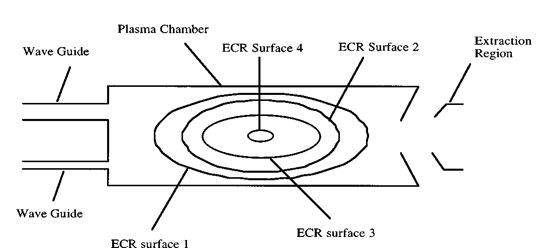
Microwaves of various frequencies can be simultaneously launched into and absorbed by a high-charge-state ECR plasma. The minimum- magnetic field configuration in an ECRIS can provide many closed and nested ECR heating surfaces, as graphically shown in Fig. 1. If two or more significantly different frequencies are used, two or more well-separated and nested ECR surfaces will exist in the ECR plasma. With the multiple ECR surfaces, electrons can be heated four times or more for one pass from one mirror end to the other, whereas they are only heated twice in the case of single-frequency heating. Multiple-frequency heating can couple more microwave power with better efficiency into the plasma and it leads to a higher density of hot electrons, which is essential for the production of highly charged ions. To demonstrate that the frequency-domain technique can be used to enhance the performance of a traditional minimum- ECR ion source, comparative studies have been undertaken to assess the relative performance of the Oak Ridge National Laboratory CAPRICE ECR ion source [10], in terms of its multiply charged ion-beam generation capability, when excited with high-power, single-frequency, or multiple-discrete-frequency microwave radiation, derived from standard klystron and/or TWT technologies. These studies demonstrate that the charge-state populations for Arq+ and Xeq+move towards higher values when excited with two- and three-discrete-frequency microwave power compared to those observed when single-frequency microwave power is used. For example, the most probable charge state for Xe is increased by one charge-state unit, while the beam intensities for charge states higher than the most probable one are increased by factors of compared to those observed for single-frequency plasma excitation. In Ref. [11], particle-in-cell codes have been used to simulate the magnetic field distributions, to demonstrate the advantages of using multiple, discrete frequencies over single frequencies to power conventional ECR ion sources.
One, two and three-frequency heating experiments have been conducted using Xe feed gas. With the addition of the second and third frequencies, the most probable Xeq+ charge state moves towards higher values by one unit; this clearly illustrates that the performance of conventional-geometry ECR ion sources can be significantly improved by the use of multiple-discrete-frequency plasma heating.
4 Electron heating with broadband microwave radiation and the volume effect
The ionization process in Electron Cyclotron Resonance (ECR) ion sources is based on the sequential removal of electrons in collisions between ions or neutral atoms with electrons that have been heated stochastically to high energies by the adsorption of microwave power under ECR conditions. The ECR zones in a conventional minimum- geometry ECRIS, powered by narrow-bandwidth microwave radiation, are thin volumes that are substantially smaller in relation to their total plasma volumes. Consequently, the probability of an acceleration resulting in a substantial energy gain for the electrons that arrive in the ECR zone in phase with the electric field vector of the electromagnetic wave is lower than is possible in extended-volume ECR zones. Therefore, it is reasonable to believe that the performance of conventional minimum- ECR ion sources can be improved by increasing their respective resonance volumes. The volume effect has been demonstrated by tailoring the central magnetic field so that it forms a large resonant volume and by increasing the number of discrete operational frequencies of the ion source. Broadband sources of RF power provide a simple and potentially more effective alternative for increasing the physical sizes of the resonance zones in conventional ECR ion sources.
4.1 Experimental procedures
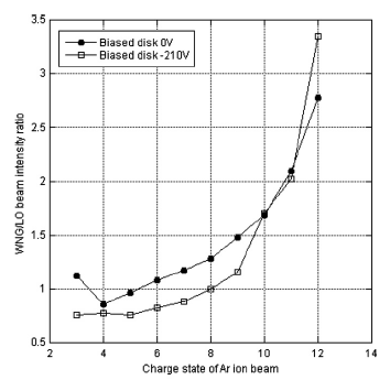
Some experiments have been performed with the JYFL 6.4 GHz conventional minimum- geometry ECR ion source at the University of Jyväskylä, using Ar as the feed gas. The performance of the source was compared when operated with either narrow or with broadband microwave radiation, under the same neutral gas pressure and input power conditions. For the narrow-bandwidth experiments, the carrier signal from the local oscillator (LO, bandwidth 1.5 MHz) was fed directly into the TWTA. For the broadband experiments, the signal from the LO was fed into a White-Noise Generator (WNG), producing an output signal with a bandwidth of 200 MHz, FWHM, equally distributed about the central frequency of the LO (6.4 GHz). The measurements were carried out at the same absorbed microwave power level (200 W), determined by subtracting the reflected power from the forward power of the TWTA. The input power was limited due to impedance mismatch of certain frequencies in the amplified broadband signal, resulting in 20 reflected power of the injected power. This problem cannot be avoided and it constitutes the main drawback of such a technique, since frequencies are differently coupled into the ion source depending on the intrinsic electromagnetic structure of the source itself. In the case of narrow- bandwidth operation, the reflected power was typically 6. For the WNG mode of operation at optimum pressure, the ion plasma density, as evaluated from the measured drain current and the charge-state distribution, using Bohm’s criterion, was within 15 of the neutral density. Although the beam intensities were higher by factors >2 with the WNG at low pressures, there was no difference between the broadband and narrow-bandwidth modes of operation in the high neutral pressure regime due to increased rates of charge exchange [13, 14]. Enlarged ECR zones improve the production of high-charge-state ions due to enhanced bombardment with higher populations of energetic electrons and, especially, due to the enhanced ionization rates of neutrals in the ECR zone, thereby lowering the probability of charge-exchange collisions. The tremendous potential of the broadband technique for enhancing high-charge-state beam intensities over conventional means at equivalent input power levels is illustrated in Fig. 2, where the ratio of WN/LO-generated high-charge-state beams is seen to increase continually with the charge state. Clearly, the potential of the broadband method can only be fully evaluated by comparing the high charge states produced with the two modes of operation at the same power density, if this is achievable in practice in terms of the operational limitations imposed by outgassing effects and the required RF power.
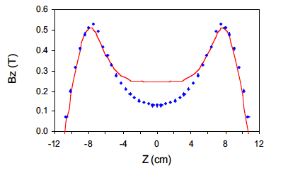
The performance of ECR ion sources can also be significantly improved by tailoring the central region of the magnetic field so that it is resonant with single-frequency microwave radiation (spatial domain) [15, 16, 17]. The spatial-domain technique employs a magnetic field configuration with an extended central flat region, tuned to be in resonance with single-frequency microwave radiation. Because of the large resonant plasma volume, significantly more RF power can be coupled into the plasma, resulting in heating of electrons over a much larger volume than is possible in conventional ECR ion sources. The ability to ionize a larger fraction of the particles in the plasma volume effectively reduces the probability of resonant and non-resonant charge exchange, thereby increasing the residence time of an ion in a given charge state and for subsequent and further ionization. All other parameters being equal, the ‘volume’ ECR source should result in higher-charge-state distributions, higher beam intensities, and improved operational stability. The axial magnetic field is shown in Fig. 3: its profile is flat (constant mod-) in the centre, and extends over the length of the central field region, along the axis of symmetry, and radially outwards to form a uniformly distributed ECR plasma ‘volume’. This magnetic field design strongly contrasts with those used in conventional ECR ion sources, where the central field regions are approximately parabolic and the consequent ECR zones are ‘surfaces’.
According to computational studies, the new configuration will result in dramatic increases in the absorption of RF power, thus enabling the heating of electrons over a much larger volume, thereby increasing the electron temperature and the ‘hot’ electron population in the plasma.
5 Frequency tuning
Many experiments over recent years have shown that significant improvements of ECRIS performance (both in terms of total extracted current and the production of highly charged ions) can be obtained by slightly varying the microwave frequency in the case of Single-Frequency Heating (SFH), this being defined as a ‘frequency tuning’ effect. It was already known that a large increase in the frequency increases (GHz) the electron density and improves the ECRIS performance because of the increase of the cut-off density, but since 2001 several experiments have demonstrated that even slight variations of the pumping wave frequency (MHz) may lead to strong variations in the extracted current. The first evidence was provided by the different performances observed for the SERSE and CAESAR ion sources when fed by a klystron-based or a TWT-based generator [19, 20, 21] at either 14 or 18 GHz. Other interesting results came from experiments performed at GSI and at JYFL. In frequency tuning, the microwave frequency is varied in order to select the most efficient heating mode inside the plasma chamber of the ECRIS. In the experiments, the input frequency for the klystron was swept from 14.05 to 14.13 GHz in 100 s, using a Rohde Schwartz signal generator. This bandwidth was found adequate to maintain a constant output power over the whole frequency sweep, using the automatic level control feature of the klystron.
5.1 Effect on beam structure and emittance
The beam emittance and the beam structure were studied as a function of the frequency with the aid of an Allison-type emittance scanner and a KBr beam viewer. Figure 4 shows three beam viewer pictures: the beam structure varies strongly with the microwave frequency, as an indication of the change in the plasma–wave coupling during the scan. However, no unequivocal explanation concerning the origin of the beam structure variations can be given: they could originate from the changes in the plasma, in the electron ion dynamics, due to electromagnetic field variations and/or in the beam line due to changes in ion-beam intensity and space charge. The explanation of the data presented above is based on the assumption that the frequency tuning changes the electromagnetic field distribution inside the resonator in terms of its distribution over the resonance surface; that is, where the wave–electron energy transfer takes place. This assumption requires that even in case of plasma filling the cavity, the resonant modes persist; that is, the formation of standing waves is still possible.

5.2 The microwave frequency dependence of the properties of the ion beam extracted from a CAPRICE-type ECRIS
Measurements have been performed with the CAPRICE-type ECRIS installed at the ECR Injector Setup (EIS) of GSI. The experimental set-up uses a microwave sweep generator that feeds a TWTA, covering a wide frequency range from 8 to 18 GHz. This arrangement provides a precise determination of the frequencies and of the reflection coefficient along with the beam properties. A sequence of viewing targets positioned inside the beam line monitors the evolution of the beam shape. In the present experiment, the frequency tuning effect has been analysed in the 12.5–16.5 GHz frequency range. The availability of a TWTA driven by a signal generator made it possible to change the source operating frequency in steps of a few hundred kilohertz. This experiment allows us to analyse the beam properties when the ECRIS operative frequency sweeps over a wide range of 4 GHz, and hence for increasing ECR surfaces. The influence on lower- and higher-charge states has been analysed for different source conditions concerning the magnetic field configuration, the gas pressure, and the power setting.
5.3 Description of experimental set-up
The CAPRICE-type [22] ECR ion source used for this experiment is equipped with a 1.2 T maximum radial magnetic field. The plasma chamber was 179 mm long and 64 mm in diameter. The RF power was provided by a TWTA working in the 8–18 GHz frequency range and able to provide an output power higher than 650 W in the frequency range of 12–18 GHz. The input of the amplifier was driven by a signal generator able to sweep from 1 to 20 GHz. According to the maximum manageable power reflected to the amplifier, it has been restricted to working at a power of 100 W and in the frequency range of 12.5–16.5 GHz. The use of a waveguide microwave isolator covering this frequency range and handling up to 650 W could allow us to work with higher powers.
The frequency steps were set to 200 kHz, with a dwell time of 20 ms for each step. The duration of one measurement was then around 400 s. Two directional couplers with high directivity were inserted in the waveguide line in order to measure the forward power and the reflected power by means of two microwave power probes. The experiment was carried out with argon and helium as support gases, at gas pressures of (3.9–5.0) mbar. The ion currents of the Ar7+, Ar8+, and Ar9+ charge states were measured using a Faraday cup; the drain current of the high-voltage power supply of the extraction was also recorded. The extraction voltage was set to 15 kV; a voltage of kV was applied to the screening electrode. Viewing targets could be remotely inserted at three positions along the beam line in order to monitor the evolution of the beam shape right after the extraction, the focused beam, and the analysed beam [23]. KBr was used as the target coating material for this experiment.
5.4 Results and discussion
Different measurements were carried out by sweeping the frequency and setting different ion source parameters; that is, the injection and extraction magnetic field values, the gas pressure, and the microwave power. The source parameters were set to operate using a charge-state distribution with a maximum on the Ar8+ current (by feeding the plasma with 100 W microwave power at 14.5 GHz). An Ar8+ current of 85 A and a drain current of 2.36 mA were obtained. From these source conditions, the frequency sweep was started by ramping the signal generator from 12.5 GHz up to 16.5 GHz, while the reflection coefficient, the Ar7+, Ar8+, and Ar9+ currents, and the drain current were recorded simultaneously. The evolution of the reflection coefficient with the frequency is shown in Fig. 5. As expected by comparison with previous experiments, the matching impedance between the cavity filled by the plasma and the electromagnetic wave is strongly dependent on the frequency [6]. It is remarkable that the plasma properties also change considerably with varying frequency. The strong correlation between the peaks of the reflection coefficient and the current amplitude are clearly visible around the frequencies at which the reflection coefficient is higher than dB (matching condition). The relationship between the resonance frequencies and the heating efficiency has been analysed theoretically and particle-in-cell codes have been used to correlate the electromagnetic field patterns and the electron cyclotron resonance surface [24]. However, it is not possible with our analysis to determine the electromagnetic field patterns (modes) related to these peaks. The comparison of the current evolution in the frequency range indicated above is presented in Fig. 5.
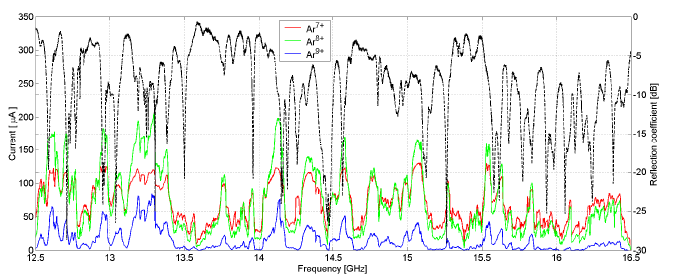
It is clear how the current amplitude is affected by the choice of the operative frequency. Looking at the Ar8+ current, it ranges from a few microamperes up to 200 A. The experimental results were clearly reproducible in several runs, thus confirming the reliability of the measurements. The evolution of the Ar7+ and Ar8+ currents is similar, but their amplitudes differ. In fact, at the frequencies at which both currents present a peak, the Ar8+ current is quite a bit higher than the Ar7+ current (e.g. at 14.119 GHz, the difference between the two currents is 80 A). The opposite behaviour is visible for the minima of the current amplitudes, where the Ar7+ current is higher than the Ar8+ current. In the range 15.64–16.5 GHz, the currents of the higher-charge states – that is, Ar9+ – tend to lower values even if the reflected power is less than 10. This seems to be due to the confining magnetic field, which restricts the source operation to lower frequencies. It has been also observed that the evolution of the drain current follows the trend of the three charge states presented in Fig. 5. In order to have a complete understanding of the sweep effects on the ionization process, the charge-state distribution has been analysed for different frequencies. It was decided to restrict the analysis to the frequency range of 14–15 GHz. Several frequencies have been considered at which peaks and minimum amplitudes occur. In Fig. 6, the charge-state distributions are presented for four different frequencies.
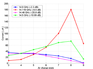
The 14.5 GHz value is the normal operational frequency of the CAPRICE ion source; 14.46 GHz and 14.119 GHz are the frequencies at which the minimum and the maximum Ar8+ currents, respectively, were measured in the 14–15 GHz frequency range. The charge-state distribution related to 14.0 GHz operation is also reported in order to emphasize the importance of the electromagnetic field pattern and the choice of the frequency. In fact, the charge-state distributions at 14.0 GHz and at 14.46 GHz are quite similar, even though the amount of power feeding the plasma was more than doubled. In the first case, the reflection coefficient (indicated in the legend of Fig. 2) was dB and more than half of the power was reflected; and in the second case it was dB, the impedance matching condition was fulfilled, and hardly any power was reflected. It is also interesting that for the frequencies at which the higher-charge states are favoured, the current of the lower charge state is decreasing and vice versa. The analysed charge-state distributions confirm that frequency tuning affects the higher-charge states to a greater extent (at 14.119 GHz, the current enhancement with respect to the 14.5 GHz operational frequency is 244 for the Ar8+ current and 456 for the Ar9+ current). The enhancement of the current is not the only effect of frequency sweeping; in fact, the quality, the shape, and the emittance of the ion beam also vary. The use of beam viewing targets has proven to be a favourable technique for monitoring the beam shape and a promising beam diagnostic tool. The images recorded beyond the extracted beam-focusing solenoid (position VT2) and in the diagnostic box after the mass/charge selection dipole (position VT3) are shown in Fig. 7.
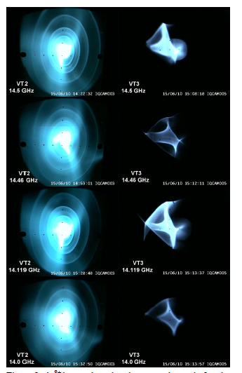
Here, the same frequencies are chosen as in Fig. 6. The Ar8+ beam is shown in the right column and the focused beam images also refer to the Ar8+ magnetic field setting. At 14.0 GHz and 14.46 GHz, which are the frequencies at which the Ar8+ current presents a minimum, the focused beam shape seems to remain unchanged in the orientation of the arms (at 14.0 GHz it is a little bit brighter, also according to the higher intensity measured at the Faraday cup). At 14.119 GHz, the focused beam is a little bit bigger and brighter than the one at 14.5 GHz, and in both cases the orientation of the arms is turned by more then 40∘ clockwise with respect to the 14–14.6 GHz beam shapes.
5.5 Frequency tuning combined with the two-frequency heating effect
The relationship between the two frequencies and the respective power was not univocally determined. In fact, any source features a different set of parameters and the optimization is done empirically, just by looking at the maximization of the beam current. Several qualitative explanations have been offered for this phenomenon, all related to the increase of the average electron temperature, Te, and to the ionization rate, by assuming that the crossing of two resonance surfaces helps the electrons to gain more energy. This simple picture does not explain the reason for the relevant changes in the charge-state distribution for different pairs of frequencies (even for the case of minor changes – such as a few megahertz over 14 or 18 GHz), which can be explained nowadays in terms of the frequency tuning effect. It is important to underline that, even in the case of TFH applied to many existing sources, a TWT is often used, the other option being a klystron-based generator. The choice of a TWT allows the experimentalists to vary the second frequency slightly. It has been observed – for example, for the production of O7+ – that 60 W emitted by the TWT at the optimum frequency gives the same effect as 300 W emitted from the fixed-frequency klystron. The maximum current is obtained by means of a klystron at 427 W and a TWT at 62 W ( = 66 A), operating simultaneously; in order to obtain the same current, the experimenters needed = 800 W from the klystron in SFH. Furthermore, in the case of TFH, the current increases almost 20 (from 57 to 66 eA) when the TWT-emitted frequency shifts from 11.06 to 10.85 GHz, the klystron and TWT emitted power both being held constant. Then, the TFH is an effective method to increase the extracted current from an ECRIS, but it can only be fully exploited by means of frequency tuning. Several measurements have been carried out with the SERSE ion source. The TFH has been used for operation at either 14 or 18 GHz, with a clear advantage with respect to SFH.
In section 5.2, the evolution of the ion current intensities of Ar7+, Ar8+, and Ar9+ over the 12.5–16.5 GHz frequency range has been described. The argon charge-state distributions were analysed for different frequencies, and for some frequencies an enhanced intensity of the higher-charge states was observed. We decided to perform an experiment to investigate the double-frequency heating effect using a single fixed frequency (14.5 GHz in one case and 14.119 GHz in another) and a second frequency swept over the 12.5–16.5 GHz range. First, the power feeding the plasma was kept at 100 W, in order to compare the results of double-frequency heating with single-frequency sweeping. Then the power distribution between the fixed frequency and the sweeping frequency was unbalanced by doubling the power of the fixed frequency in one case and the power of the sweeping frequency in the other. The ion source parameters – including the magnetic field, the gas pressure, the extraction voltage, and so on – were set to and maintained at the same values as used for single-frequency sweep analysis, with the charge-state distribution optimized for the Ar8+ intensity. The Ar7+, Ar8+, and Ar9+ currents were recorded together with the extractor drain current. The forward power and the reflected power were measured simultaneously. However, in the case of double-frequency heating, the power probes cannot distinguish the measured values of the forward and reflected power related to each of the two waves. The results of these measurements are shown in Fig. 8.
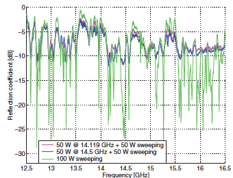
A comparison between the two techniques concerning the behaviour of the ion source is possible. As expected, in the case of the two frequencies, the minima of the reflection coefficient are higher because of the higher level of reflected power due to the superposition of the two waves. It is interesting to note that these minima occur at almost the same frequencies for both techniques. Since the positions of the reflection coefficient minima do not vary, it can be expected that the peaks of the ion current are located at the same frequencies for the two heating methods. This comparison is shown in Fig. 9 for the drain current of the high-voltage extractor power supply. In this case, 50 W is provided at one fixed frequency and the effect of sweeping a second frequency with a power of 50 W produces a different current behaviour from that with a single sweeping frequency (at the same power). This can be seen in Fig. 9 and Figs. 10–11. In fact, during the single-frequency sweep, the drain current
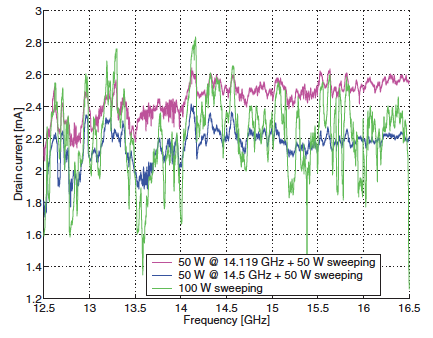
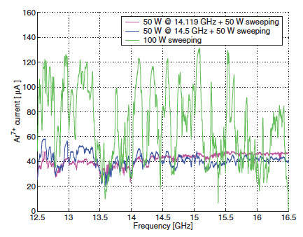
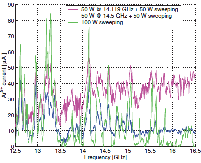
varies from around 1.4 mA to 2.8 mA, while with double-frequency heating the range of variation is 0.6 mA. The drain current appears more stable with frequency when the double frequency is applied instead of single-frequency tuning. This behaviour is also observed in the Ar7+ current variation shown in Fig. 10. A possible explanation might be found in the microwave power provided by the two methods. In the case of single-frequency tuning, 100 W is provided to the source and during the frequency sweep, when the impedance is not matched, most of the forward power is not coupled to the source but is reflected (see Fig. 8). But in the case of double-frequency heating, just 50 W of the total forward power of 100 W is associated with the sweeping frequency, and at the frequencies at which the power is not coupled to the plasma, one half of the total power is provided at a fixed frequency, which is well coupled to the source (i.e. at 14.5 GHz or at an optimized frequency such as 14.119 GHz). The choice of the fixed frequency allows enhancement of the ion currents of the higher-charge states. With respect to single-frequency operation, with two frequencies the current peaks are broadened and reduced in amplitude, the frequencies at which they occur remain the same, and the average current level remains high (see Fig. 10 for Ar7+), while the higher-charge states tend to higher ion currents when the frequency is increased (see Figs. 11 and 12). The experimental results indicate that there can be strong differences when the operating frequency is optimized by frequency tuning. In fact, when operating in double-frequency mode and optimizing one of the two frequencies (14.119 GHz for the present case, as described above), the current increases linearly with frequency (with respect to the 14.5 GHz fixed frequency).
In comparing the two techniques while keeping the ion source settings and the microwave power constant, note that the behaviour of the ion currents and the reflection coefficient remain almost the same with frequency. This result is useful to optimize the performance of an ECRIS further when double-frequency heating is used. In fact, single-frequency tuning can be used to find the optimum frequencies to be used for operating in the multiple heating mode. Note also that when operating with two generators set at the same frequency, the current level measured is different from the single-generator case. This is because when the two frequencies become equal, the current of each charge state and the power provided to the ion source are not stable. A possible explanation for this phenomenon might be overlapping of the two signals and the phase difference between the two waves. We plan to explore the use of two phase-locked generators in forthcoming experiments. The behaviour of argon ion beams has been explored for different power levels of the fixed frequency and the sweep frequency. In both cases, two fixed frequencies were chosen and in this case the possibility of setting the fixed frequency to an optimized value, obtained by fine-tuning the frequency, allowed us to increase the beam intensity (Fig. 13).
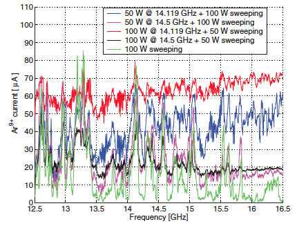
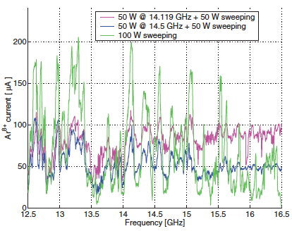
Figure 13 shows the evolution of the Ar9+ current when 150 W of total power is distributed between the two microwave feeds in different proportions, one of fixed frequency and the second swept from 12.5 GHz to 16.5 GHz. Again, the single-frequency sweep carried out at 100 W is included in the figure for comparison. For the optimum frequency mentioned previously (14.119 GHz), the current intensity is still comparable between the two methods even though the total power is 50 greater.
When the power associated with the fixed frequency is higher, all the analysed charge states are less sensitive to variation of the second frequency. This follows from the reduced dynamic range of the current, indicating a more stable plasma; in particular, when the fixed frequency is chosen to be at the optimum value (14.119 GHz). Furthermore, when one of the two frequencies is optimized, the average extracted current remains high with respect to an unoptimized frequency (such as 14.5 GHz), increasing with the second frequency (quite evident above 15 GHz). All these observations are more evident for higher-charge states. With the ion source running at higher microwave power, it was possible to perform an experiment with an Ar11+ ion beam. The results are shown in Fig. 14.

The power distribution between the two waves is also important. Obviously, it is more effective to increase the power at the fixed frequency. Figure 14 shows once more that the choice of the optimum frequency, as obtained in the previous experiment on frequency tuning, is very important for double-frequency heating at higher power. This result is interesting with respect to the operation of new-generation ECRIS machines working at 28 GHz, using gyrotron microwave generators in combination with a second microwave generator of lower frequency, working in double-frequency mode.
6 Alternative heating method: Bernstein waves
ECR devices are density limited, because the electromagnetic waves cannot propagate beyond a certain density, called the cut-off density. An alternative to the classical ECR interaction is electrostatic wave heating, driven by Bernstein waves. Bernstein waves (BW) are very interesting for nuclear fusion devices [25], because the plasma heating occurs in the absence of any density cut-off. Electromagnetic Ordinary (O) or Extraordinary (X) modes can be externally launched into the plasma. O-mode waves may be coupled to an X mode in the O-mode cut-off layer, and then the X mode can be coupled to a BW mode at the upper hybrid resonance (UHR). This process is called O-X-B mode conversion and was described in 1973 by Preinhaelter and Kopecky [25].
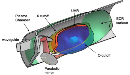
It was shown that O-X-B mode conversion may be optimized by changing the O-mode insertion angle with respect to the external magnetic field direction: in this case, the O mode is completely converted into a slow X mode, which under certain conditions is in turn converted to BWs in the Upper Hybrid Resonance (UHR) layer [26]. The generated Bernstein waves travel inside the plasma until they are absorbed at the ECR or at the higher-order cyclotron harmonics. A possible design for a microwave injection system producing the O-X-B conversion is shown in Fig. 15: first, an O wave is launched from the outside, with an oblique angle of incidence obtained with a proper orientation of the parabolic mirrors. For an optimal launch angle, it is possible to obtain a correlated optimal parallel refractive index and then a coincidence of the O and X modes at the critical plasma density (cut-off). This means that both modes have the same phase and group velocities and the power is transferred without reflections. Once the X waves are generated, they propagate towards the UHR. Here, the X mode coincides with the electron Bernstein mode. In the linear description, the X waves are completely converted into EBWs. This process is called X–B conversion. It should be noted that the O-X-B process can only take place if the plasma density is above the O-wave cut-off density.
O-X-B plasma heating and current driving with BW in an overdense plasma were demonstrated in the Stellarator WEGA, operating at the Max Planck Institute for Plasma Physics in Greifswald, Germany [27]. The heating of a plasma by means of EBW at particular frequencies enabled us to reach densities much larger than the cut-off ones. Evidence of EBW generation and absorption together with X-ray emissions due to high-energy electrons is shown in ray tracing simulations and CCD photographs in Ref. [29].
A plasma reactor operating at the Laboratori Nazionali del Sud of INFN, Catania, has been used as a test-bench for the investigation of innovative mechanisms of plasma ignition based on electrostatic waves (ES-W), obtained via the inner plasma EM-to-ES wave conversion. Evidence of Bernstein wave (BW) generation is shown in Ref. [28].
In particular, during the experiment, a microwave discharge ion source has been used: a plasma reactor consisting of a stainless-steel cylinder that is 24 cm long and 14 cm in diameter. A NdFeB permanent magnet system generates an off-resonance magnetic field along the plasma chamber axis (with a maximum of 0.1 T on axis).
Microwaves have been generated by using a TWT, which is able to generate microwaves from 3.2 to 4.9 GHz. The typical working frequency when using the TWT was 3.7478 GHz. The temperature and plasma density measurements have been carried out by using a movable Langmuir Probe (LP). The LP can host a small wire used as a local electromagnetic antenna, which can be connected to a spectrum analyser for the plasma spectral emission analysis. An Si-Pin and a HPGe X-ray detector have been used for the measurement of X-ray spectra in different plasma conditions. Both detectors are able to detect X rays with energies greater than about 1 keV. A CCD camera has been used to visualize the plasma structure within the chamber at different working frequencies, and at different microwave powers and pressures. A series of LP measurements has been carried out with the plasma reactor at the frequency of 2.45 GHz, when both under-resonance and off-resonance regions are present. In Fig. 16, it is evident that the electron density is drastically enhanced in regions where the condition is satisfied.
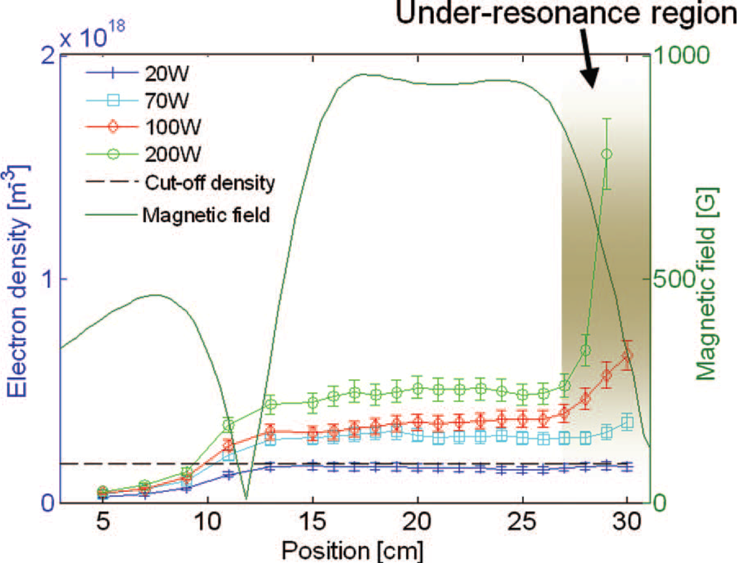
This effect is observed for all of the different power values that we used; in particular, at 200 W, an electron density of about cm−3 has been measured, a value 20 times greater than the cut-off density. Note that the electron density is everywhere comparable or larger than the cut-off density ( cm−3). In the same magnetic configuration, X-ray measurements have been carried out at 2.45 GHz and 3.7478 GHz. By increasing the pumping frequency, it is possible totally to remove the ECR, so that at 3.7478 GHz the entire plasma chamber is at under-resonance and EBW heating becomes the unique heating mechanism. Spectral temperatures measured in the two cases are shown in Fig. 17.
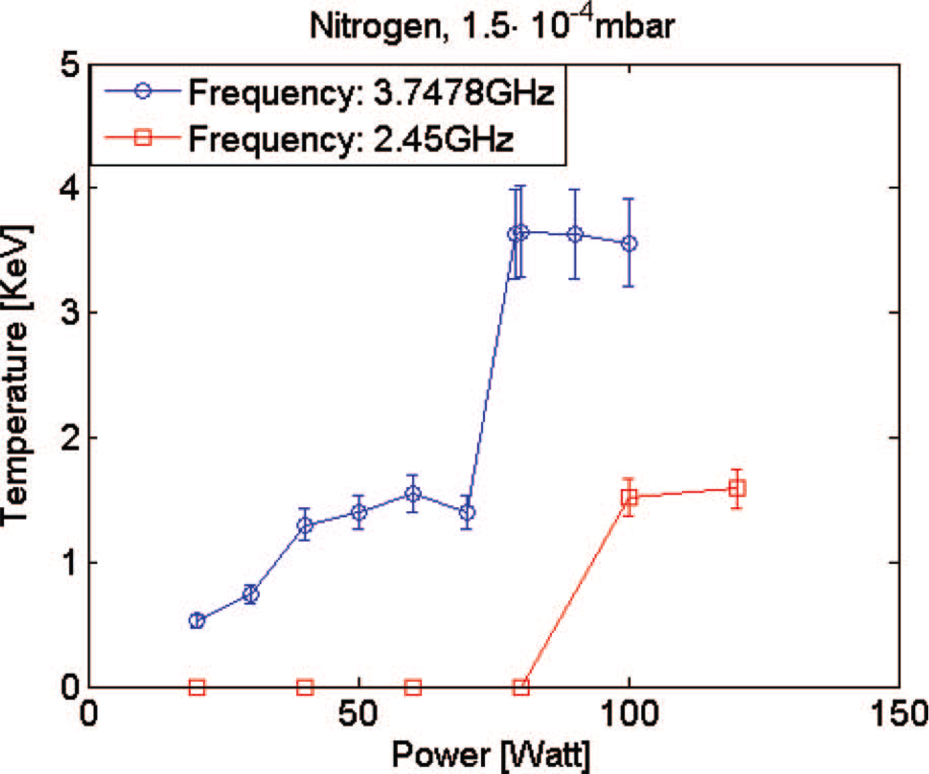
At the frequency of 3.7478 GHz, the spectral temperature is significantly larger (up to 4 keV) than at 2.45 GHz. Around 80 W, it is possible to identify a threshold for which the temperature slope increases suddenly and becomes steeper for both configurations. The end-point energy is about 10 times the value of the spectral temperature. The spectral temperature decreases slightly with the atomic mass of the gas used and when the pressure is increased. Further results and discussion can be found in Ref. [29]. The results are interpreted through the Bernstein wave heating theory, and are very promising for future high-intensity multicharged ion sources that can, therefore, be based on the results described here, by employing a simplified magnetic configuration with respect to typical minimum- ECR ion sources.
7 Conclusion
Microwave coupling to ECR ion sources plays a fundamental role in enhancing their performance in terms of current extracted and average charge state produced. Over the past decade, new heating methods have been studied to overcome the technological limitations due to the magnetic field and frequency scaling, to achieve the production of milliampere levels of HCI, as requested for the new accelerating facilities all over the world.
References
- [1] S. Gammino, High Energy Phys., Nucl. Phys. 31 (2007) 137.
- [2] A.G. Drentje, Rev. Sci. Instrum. 74 (2003) 2631.
- [3] Y. Kawai, G.D. Alton, O. Tarvainen, P. Suominen, and H. Koivisto, Rev. Sci. Instrum. 77 (2006) 03A331.
- [4] Z.Q. Xie and C.M. Lyneis, Rev. Sci. Instrum. 66 (1995) 4218.
- [5] R.C. Vondrasek, R.H. Scott, R.C. Pardo, and H. Koivisto, Operational improvements of the Argonne ECR sources, Proc. 15th Int. Workshop ECR Ion Sources, Jyvaskyla, Finland, 12–14 June 2002.
- [6] G.D. Alton et al., Rev. Sci. Instrum. 69 (1998) 2305.
- [7] L. Celona, G. Ciavola, F. Consoli, S. Gammino, F. Maimone et al., Observations of the frequency tuning effect in the 14 GHz CAPRICE ion source, Rev. Sci. Instrum. 79 (2008) 023305.
- [8] S. Gammino and G. Ciavola, ECR ion sources and scaling laws, Proc. 14th Int. Conf. Cycl. Capetown, South Africa, 1995, p. 377.
- [9] D. Hitz et al., The comparison of 18 and 28 GHz behavior of SERSE: some conclusions, Proc. 15th Int. Workshop ECR Ion Sources. Jyvaskyla, Finland, 2002, p. 100.
- [10] G.D. Alton, F.W. Meyer, Y. Liu, J.R. Beene, and D. Tucker. Enhancing the performances of traditional electron cyclotron resonance ion sources with multiple-discrete-frequency microwave radiation, Rev. Sci. Instrum. 69 (1998) 2305.
- [11] G.D. Alton, Computational studies for a multiple-frequency electron cyclotron resonance ion source.Rev. Sci. Instrum. 67 (1996) 989.
- [12] Z.Q. Xie, Production of highly charged ion beams from electron cyclotron resonance ion sources (invited), Rev. Sci. Instrum. 69 (1998) 625.
- [13] O. Tarvainen, Y. Kawai, G.D. Alton, P. Suominen, and H. Koivisto, Electron heating with broadband microwave radiation: a new method for improving the performances of conventional -minimum electron cyclotron resonance ion sources, Nucl. Instrum. Methods Phys. Res. B 261 (2007) 1044.
- [14] Y. Kawai, G.D. Alton, O. Tarvainen, P. Suominen, and H. Koivisto, Effect of broadband microwave radiation on the performance of a conventional -minimum geometry electron cyclotron resonance ion source, Rev. Sci. Instrum. 77 (2006) 03A331.
- [15] G.D. Alton and D.N. Smithe, Rev. Sci. Instrum. 65 (1994) 775.
- [16] G.D. Alton and D.N. Smithe, Physica Scripta T71 (1996) 66.
- [17] G.D. Alton, Proc. 14th Int. Conference on Cyclotrons and their Applications (Capetown, South Africa, 8–13 October 1995), Ed. J.C. Cornell, World Scientific, Singapore, p. 362.
- [18] G.D. Alton and Y. Liu, Enhancing the performances of ECR ion source, Proc. 1999 Particle Accelerator Conference, New York (1999).
- [19] L. Celona et al., Analysis of the SERSE ion output by using klystron-based or TWT-based microwave generators, Proc. AIP Conf., vol. 749 (2005), p. 99.
- [20] S. Gammino, G. Ciavola, and L. Celona. Nucl. Instrum. Methods Phys. Res. A, 491 (2002) 342.
- [21] R. Vondrasek et al., AIP Conf. Proc., vol. 749 (2005), p. 31.
- [22] D. Hitz, A. Girard, K. Serebrennikov, G. Melin, D. Cormier, J.M. Mathonnet, J. Chartier, L. Sun, J.P. Briand, and M. Benhachoum, Rev. Sci. Instrum. 75 (2004) 1403.
- [23] J. Mäder et al., Rev. Sci. Instrum. 81 (2010) 174.
- [24] D. Mascali et al., Rev. Sci. Instrum. 81 (2010) 02A334.
- [25] H.P. Laqua et al., Plasma Phys. Control. Fusion 41 (1999) A273.
- [26] N.A. Krall and A.W. Trivelpiece, Principles of Plasma Physics (San Francisco Press, San Francisco, CA, 1986).
- [27] Y.Y. Podoba, H.P. Laqua, G.B. Warr, M. Schubert, M. Otte, S. Marsen, F. Wagner, and E. Holzhauer, Phys. Rev. Lett. 98 (2007) 255003.
- [28] D. Mascali, L. Celona, S. Gammino, R. Miracoli, G. Castro, N. Gambino, and G. Ciavola, Electrostatic wave heating and possible formation of self-generated high electric fields in a magnetized plasma, Nucl. Instrum. Methods Phys. Res. A. 653 (2011) 11.
- [29] G. Castro, D. Mascali, F. P. Romano, L. Celona, S. Gammino et al., Comparison between off-resonance and electron Bernstein waves heating regime in a microwave discharge ion source, Rev. Sci. Instrum. 83 (2012) 02B501.