Multi-Material Coatings with Reduced Thermal Noise
Abstract
The most sensitive measurements of time and space are made with resonant optical cavities, and these measurements are limited by coating thermal noise. The mechanical and optical performance requirements placed on coating materials, especially for interferometric gravitational wave detectors, have proven extremely difficult to meet despite a lengthy search. In this paper we propose a new approach to high performance coatings; the use of multiple materials at different depths in the coating. To support this we generalize previous work on thermal noise in two-material coatings to an arbitrary multi-material stack, and develop a means of estimating absorption in these multi-material coatings. This new approach will allow for a broadening of the search for high performance coating materials.
pacs:
I Introduction
Lasers and resonant optical cavities have become a ubiquitous tool in optical experiments which explore the bounds of physics through precise measurements of space and time McClelland et al. (2011); Schnabel et al. (2010); Poot and van der Zant (2012); ZAVATTINI et al. (2012). The precision with which these measurements can be made is in large part determined by the fundamental thermal motion of the coatings used in optical resonators Kessler et al. (2012); Cole et al. (2013); Adhikari (2014).
Interferometric gravitational wave detectors in particular set extremely stringent requirements on their coatings; they must simultaneously have good mechanical properties for low thermal noise, low optical absorption for high-power operation, and good surface figure to support multi-kilometer resonant cavities Fritschel (2014). These requirements are, however, very hard to meet in a single material Crooks et al. (2002); Harry et al. (2002); Yamamoto et al. (2002); Penn et al. (2003); Black et al. (2004); Crooks et al. (2006); Harry et al. (2006, 2007); Abernathy et al. (2008); Martin et al. (2008, 2009); Flaminio et al. (2010).
This paper provides the theoretical foundation for a new approach to the search for high quality coating materials. We compute the coating thermal noises and absorption which will result from coatings comprised of a variety of materials. This is to be contrasted with previous works, which have assumed that optical coatings are made of one low-index material and one high-index material Hong et al. (2013); Evans et al. (2008).
In the next section we present our model of coating Brownian and thermo-optic noises, generalized from previous works to allow for multi-material coatings. We go on to develop a simple model of absorption as a function of depth in the coating, from which we are able to assess the impact of using relatively high absorption materials deep in the coating. These calculations are followed by a few example of how this new approach can be used to produce coatings with lower thermal noise. All frequently used symbols are given in table 1, and appendix A connects the notation used in this work to that of previous authors.
II Model of Coating Thermal Noise
In order to elucidate the potential benefits of multi-material coatings we will first describe briefly the model of thermal noise used in our calculations. For Brownian thermal noise we start with Hong et al. (2013), and Evans et al. (2008) is our starting point for thermo-optic noise, though similar treatments can be found in Gorodetsky (2008); Gurkovsky and Vyatchanin (2010); Kondratiev et al. (2011).
Since Hong et.al.Hong et al. (2013) conclude that changes in the ratio of shear to bulk mechanical loss do not significantly change the optimal coating design, and that photoelastic effects are relatively unimportant, we can simplify their result significantly by assuming that shear and bulk mechanical losses are equal, , and that the photoelastic effects can be ignored. (While not important for optimization, the ratio of shear and bulk losses impacts the level of Brownian thermal noise at the level Hong et al. (2013).) The resulting equation for Brownian thermal noise is
| (1) |
where the unitless weighting factor for each layer is
Under the assumption that the substrate and coating elastic parameters are equal ( and ), and ignoring field penetration into the coating (), for all layers.
For thermo-optic noise we use
| (2) |
where
| (3) | |||||
| (4) | |||||
| (5) |
Note that the expression for is slightly different from that of Evans et al. (2008), thanks to the correction by K. Yamamoto in chapter 8.2.5 of Harry et al. (2012).
In this paper we make a number of simplifying assumptions (, no photoelastic effect), and we ignore several correction factors (thick coating correction Evans et al. (2008), finite size test-mass corrections Braginsky and Vyatchanin (2003); Somiya and Yamamoto (2009)). All of this is to keep the formalism simple enough that the results can be easily understood and evaluated, but it should not be taken to mean that these corrections cannot be applied to multi-material coatings. Indeed, their application is expected to be a straight-forward if somewhat messy process.
II.1 Reflection Phase
In this section we summarize the model for coating reflectivity presented in Appendix B of Evans et al. (2008), as this calculation forms the basis for computing the coating phase sensitivity to mechanical and thermal fluctuations (e.g., in eqns 1 and 5). In the next section, we extend this computation to include distributed absorption in coating materials, which is an essential ingredient in the primary result of this paper.
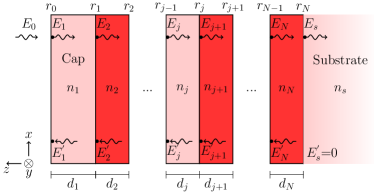
As in Evans et al. (2008), we express the reflectivity of the interface between two coating layers, seen by a field moving from layer to layer (see figure 1), as
| (6) |
By recursively combining the interface reflectivities , we can find the reflectivity of layer and all of the layers between it and the substrate
| (7) |
Note that while includes the roundtrip propagation phase in layer , it does not include the reflectivity of the interface between layer and .
The expression for is recursive and the base case is the transition from the coating layer to the substrate,
| (8) |
which can be evaluated with (6) using . Total coating reflectivity is evaluated with the external vacuum acting as layer zero such that .
The sensitivity of the coating reflection phase to a change in layer
| (9) |
is given by the recursion relation
| (10) |
with the recursion starting at , progressing through increasing values of , and terminating at .
II.2 Optical Absorption
Maintaining extremely low optical absorption in high-reflection coatings severely limits the choice of coating materials Beauville and others (2004). The key idea behind this paper and its experimental counterpart Steinlechner et al. (2015), is that this stringent requirement need not be applied to all layers in the coating, but only to those near the surface which are dominantly responsible for the absorption of the coating.
To compute the depth dependence of optical absorption in a coating, we start by evaluating the electric field present in each layer of the coating
| (11) |
(see figure 1). This expression can be used iteratively to compute the field entering each coating layer given that the field entering the coating from the vacuum is , where is the power of the incident laser beam, while and are the speed of light and the permittivity of free space (see Hong et al. (2013) or Appendix A of Kwee et al. (2014)).
The field at any point in a given layer will be the sum of the two counter propagating fields
| (12) | |||
| (13) |
such that at the top of layer , and at the bottom. Optical absorption per unit length in a layer is assumed to be proportional to the time averaged field amplitude squared integrated over that layer, normalized by the power entering the layer and the layer thickness
| (14) | |||||
| (15) |
Note that the second term is zero for quarter-wave layers (i.e., with ), and that is constructed such that for (i.e., for a field propagating in the absence of a counter propagating field).
Using equation (11) we can further relate the absorption in each layer to the total absorption coefficient for the coating , by
| (16) |
and is the absorption per unit length of the material used in layer .
Absorption loss in coatings is usually quoted as a single value, the total , rather than an absorption per unit length for the coating constituents Abernathy et al. (2008); Flaminio et al. (2010). Using equation 16 we can convert absorption values in the literature into absorption per unit length. Assuming that odd layers are with negligible absorption,
| (17) |
which we use to compute the value for presented in table 2.
| symbol | name | unit or value |
|---|---|---|
| Boltzmann’s constant | ||
| mean temperature | ||
| vacuum laser wavelength | ||
| laser wavenumber | ||
| Gaussian beam radius ( power) | ||
| angular frequency | ||
| Brownian noise | ||
| Thermo-optic noise | ||
| refractive index | ||
| thermal expansion | ||
| thermal conductivity | ||
| heat capacity per volume | ||
| Young’s Modulus | ||
| Poisson ratio | ||
| mechanical loss angle | ||
| optical absorption | ||
| coating thickness | ||
| depth in the coating (negative) | ||
| laser power arriving at each layer | ||
| complex electric field amplitude | ||
| complex amplitude reflectivity | ||
| power absorption ratio | ||
| Brownian weight coefficient |
| property | unit | ||||
|---|---|---|---|---|---|
| 1.45 | 2.1 | 2.1 | 3.0 | 1 | |
| 0.51 | 3.6 | 3.0 | 3.0 | ||
| 8 | 14 | 10 | 10 | ||
| 1.38 | 33 | 30 | 30 | ||
| 1.64 | 2.1 | 2.0 | 2.0 | ||
| 72 | 140 | 100 | 70 | ||
| 0.17 | 0.23 | 0.2 | 0.2 | 1 | |
| 0.4 | 3.8 | 1.0 | 1.0 | ||
| 2 | 10 | 100 |
III Example Coatings
Given the coating model described in the previous section, and a pallet of possible coating materials, we can evaluate the impact of using more than two materials to make a coating. In this paper we allow ourselves two hypothetical coating materials, metal-oxide A and B ( and ) as a means of demonstrating the types of optimizations which can occur (see table 2).
The coating examples presented in this section are designed to show how multi-material coatings can in principal be used to produce low-noise coatings. For a detailed application of this approach to three-material coatings involving amorphous silicon see Steinlechner et al. (2015).
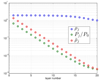
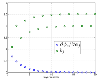
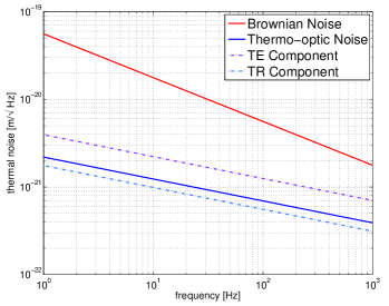
As a baseline, we start by computing the thermal noise seen by light for a 20-layer coating, made of 10 - layer pairs or “doublets”. The top layer, known as the “cap” has an optical thickness equal to half of the laser wavelength, such that . All of the deeper coating layers are quarter-wave with . The results of calculations for this coating are shown in figures 2, 3 and 4. This coating transmits 0.1% of the incident light power, and absorbs .
For comparison, we can change the high-index material used below the top 3 coating doublets to , which is similar to but is somewhat softer, has lower mechanical loss, and much higher absorption. The lower Young’s modulus makes a better match to the substrate, and combines with the lower to reduce the Brownian noise of this coating to 70% of the baseline coating. The transmission of this coating is the same as the baseline, and the absorption is only slightly higher at .
A more extreme example is a coating made of 4 - doublets, and 3 - doublets. This coating has less than 70% of the Brownian noise of the baseline coating, and only absorption. The high refractive index of this material means that fewer and thinner layers are needed relative to to produce the same transmission. This, in combination with the good mechanical properties of this coating, more than compensate for its high absorption of .
IV Conclusions
Precision optical measurements are increasingly limited by coating thermal noise, and much time and effort has been and continues to be spent in the search for better coating materials Kessler et al. (2012). In this work we suggest that the search for coating materials should not focus on finding a single material which satisfies all requirements, but rather a pallet of materials which together can be used to make coatings which satisfy all requirements.
While a single high-index, low absorption and low mechanical loss material would be ideal, the examples in this work show that a high-index material with low mechanical loss, but not necessary low optical absorption, will suffice to make lower noise coatings possible. Since the material properties of a given coating layer depend not only on its constituents (e.g., doping), but also on the manufacturing process (e.g., annealing) a wide range of material properties have already been measured or are potentially accessible.
Acknowledgements.
The authors gratefully acknowledge the support of the National Science Foundation and the LIGO Laboratory, operating under cooperative Agreement No. PHY-0757058. This paper has been assigned LIGO Document No. LIGO-P1400206.Appendix A Relation to Other Works
The expressions in this work are related to those of Hong et al. (2013) by
| (18) | |||||
| (19) | |||||
| (20) |
with our expression on the left of each equality and theirs on the right. The factor of 2 results form our definition of as a round-trip phase in each layer, while theirs is a one-way phase.
We did, however, follow the convention of Hong et al. (2013) for the direction of the z-axis: normal to the surface of the coating and pointing into the vacuum. This represents a sign reversal relative to Evans et al. (2008), such that is generally positive in this work as in Hong et al. (2013).
An earlier treatment of Brownian thermal noise which included field penetration effects was performed in Gurkovsky and Vyatchanin (2010). They based their computation on the coating reflection phase sensitivity to interface displacements (rather than layer thickness changes) and their notation is connected to ours by
| (21) |
again with our expression on the left of the equality and theirs on the right.
References
- McClelland et al. (2011) D. McClelland, N. Mavalvala, Y. Chen, and R. Schnabel, Laser & Photonics Reviews , 677 (2011).
- Schnabel et al. (2010) R. Schnabel, N. Mavalvala, D. E. McClelland, and P. K. Lam, Nature Communications 1, 121 (2010).
- Poot and van der Zant (2012) M. Poot and H. S. J. van der Zant, Physics Reports 511, 273 (2012).
- ZAVATTINI et al. (2012) G. ZAVATTINI, U. GASTALDI, R. PENGO, G. RUOSO, F. D. VALLE, and E. MILOTTI, International Journal of Modern Physics A 27, 1260017 (2012).
- Kessler et al. (2012) T. Kessler, C. Hagemann, C. Grebing, T. Legero, U. Sterr, F. Riehle, M. J. Martin, L. Chen, and J. Ye, Nature Photonics 6, 687 (2012).
- Cole et al. (2013) G. D. Cole, W. Zhang, M. J. Martin, J. Ye, and M. Aspelmeyer, Nature Photonics 7, 644 (2013).
- Adhikari (2014) R. Adhikari, Reviews of Modern Physics 86, 121 (2014).
- Fritschel (2014) P. Fritschel, submitted to Classical and Quantum Gravity (2014).
- Crooks et al. (2002) D. Crooks, P. Sneddon, G. Cagnoli, J. Hough, S. Rowan, M. M. Fejer, E. Gustafson, R. Route, N. Nakagawa, and D. Coyne, Classical and Quantum Gravity 19, 883 (2002).
- Harry et al. (2002) G. M. Harry, A. M. Gretarsson, P. R. Saulson, S. E. Kittelberger, S. D. Penn, W. J. Startin, S. Rowan, M. M. Fejer, D. Crooks, and G. Cagnoli, Classical and Quantum Gravity 19, 897 (2002).
- Yamamoto et al. (2002) K. Yamamoto, M. Ando, K. Kawabe, and K. Tsubono, Phys. Lett. A 305, 18 (2002).
- Penn et al. (2003) S. D. Penn et al., Class. Quant. Grav. 20, 2917 (2003), gr-qc/0302093 .
- Black et al. (2004) E. D. Black, A. Villar, K. Barbary, A. Bushmaker, J. Heefner, S. Kawamura, F. Kawazoe, L. Matone, S. Meidt, S. R. Rao, K. Schulz, M. Zhang, and K. G. Libbrecht, Physics Letters A 328, 1 (2004).
- Crooks et al. (2006) D. R. M. Crooks, G. Cagnoli, M. M. Fejer, G. Harry, J. Hough, B. T. Khuri-Yakub, S. Penn, R. Route, S. Rowan, P. H. Sneddon, I. O. Wygant, and G. G. Yaralioglu, Classical and Quantum Gravity 23, 4953 (2006).
- Harry et al. (2006) G. M. Harry, H. Armandula, E. Black, D. Crooks, G. Cagnoli, J. Hough, P. Murray, S. Reid, S. Rowan, and P. Sneddon, Applied Optics 45, 1569 (2006).
- Harry et al. (2007) G. M. Harry, M. R. Abernathy, A. E. Becerra-Toledo, H. Armandula, E. Black, K. Dooley, M. Eichenfield, C. Nwabugwu, A. Villar, D. R. M. Crooks, G. Cagnoli, J. Hough, C. R. How, I. MacLaren, P. Murray, S. Reid, S. Rowan, P. H. Sneddon, M. M. Fejer, R. Route, S. D. Penn, P. Ganau, J.-M. Mackowski, C. Michel, L. Pinard, and A. Remillieux, Class. Quantum Grav. 24, 405 (2007).
- Abernathy et al. (2008) M. R. Abernathy, G. M. Harry, F. Travasso, I. Martin, S. Reid, S. Rowan, J. Hough, M. M. Fejer, R. Route, S. Penn, H. Armandula, and A. Gretarsson, Physics Letters A 372, 87 (2008).
- Martin et al. (2008) I. Martin, H. Armandula, C. Comtet, M. M. Fejer, A. Gretarsson, G. Harry, J. Hough, J.-M. M. Mackowski, I. MacLaren, C. Michel, J.-L. Montorio, N. Morgado, R. Nawrodt, S. Penn, S. Reid, A. Remillieux, R. Route, S. Rowan, C. Schwarz, P. Seidel, W. Vodel, and A. Zimmer, Classical and Quantum Gravity 25, 055005 (2008).
- Martin et al. (2009) I. W. Martin, E. Chalkley, R. Nawrodt, H. Armandula, R. Bassiri, C. Comtet, M. M. Fejer, A. Gretarsson, G. Harry, D. Heinert, J. Hough, I. MacLaren, C. Michel, J.-L. Montorio, N. Morgado, S. Penn, S. Reid, R. Route, S. Rowan, C. Schwarz, P. Seidel, W. Vodel, and A. L. Woodcraft, Classical and Quantum Gravity 26, 155012 (2009).
- Flaminio et al. (2010) R. Flaminio, J. Franc, C. Michel, N. Morgado, L. Pinard, and B. Sassolas, Classical and Quantum Gravity 27, 084030 (2010).
- Hong et al. (2013) T. Hong, H. Yang, E. Gustafson, R. Adhikari, and Y. Chen, Physical Review D 87, 082001 (2013).
- Evans et al. (2008) M. Evans, S. Ballmer, M. Fejer, P. Fritschel, G. Harry, and G. Ogin, Physical Review D 78 (2008).
- Gorodetsky (2008) M. L. Gorodetsky, Physics Letters A 372, 6813 (2008).
- Gurkovsky and Vyatchanin (2010) A. Gurkovsky and S. Vyatchanin, Physics Letters A 374, 3267 (2010).
- Kondratiev et al. (2011) N. M. Kondratiev, A. G. Gurkovsky, and M. L. Gorodetsky, Physical Review D 84, 022001 (2011).
- Harry et al. (2012) G. Harry, T. P. Bodiya, and R. DeSalvo, Optical coatings and thermal noise in precision measurement (Cambridge University Press, 2012).
- Braginsky and Vyatchanin (2003) V. B. Braginsky and S. P. Vyatchanin, Physics Letters A 312, 244 (2003).
- Somiya and Yamamoto (2009) K. Somiya and K. Yamamoto, Physical Review D 79, 102004 (2009).
- Beauville and others (2004) F. Beauville and others, Class.Quant.Grav. 21, S935 (2004).
- Steinlechner et al. (2015) J. Steinlechner, I. W. Martin, J. Hough, C. Kruger, S. Rowan, and R. Schnabel, Thermal Noise Reduction and Absorption Optimisation via Multi-Material Coatings, Tech. Rep. LIGO-P1400227 (Max-Planck-Institut fur Gravitationsphysik, 2015) https://dcc.ligo.org/LIGO-P1400227.
- Kwee et al. (2014) P. Kwee, J. Miller, T. Isogai, L. Barsotti, and M. Evans, Physical Review D 90, 062006 (2014).