Plasma wakefield acceleration studies using the quasi-static code WAKE
Abstract
The quasi-static code WAKE [P. Mora and T. Antonsen, Phys. Plasmas 4, 217(1997)] is upgraded to model the propagation of an ultra-relativistic charged particle beam through a warm background plasma in plasma wakefield acceleration. The upgraded code is benchmarked against the full particle-in-cell code OSIRIS [Hemker et al., Phys. Rev. ST Accel. Beams 3, 061301(2000)] and the quasi-static code QuickPIC [Huang et al., J. Comp. Phys. 217, 658 (2006)]. The effect of non-zero plasma temperature on the peak accelerating electric field is studied for a two bunch electron beam driver with parameters corresponding to the plasma wakefield acceleration experiments at FACET. It is shown that plasma temperature does not affect the energy gain and spread of the accelerated particles despite suppressing the peak accelerating electric field. The role of plasma temperature in improving the numerical convergence of the electric field with the grid resolution is discussed.
I Introduction
In plasma wakefield acceleration (PWFA), a relativistic electron beam propagates through a plasma and drives electric and magnetic fields known as wakefields Chen et al. (1985). In the blowout regime Rosenzweig et al. (1991); Lu et al. (2006), a short (approximately one plasma wavelength long, where is the speed of light and is the plasma frequency) and high current electron beam driver with density larger than the plasma density radially expels all the plasma electrons in its vicinity. As the beam passes by, the expelled electrons are pulled back towards the beam axis by the positive charge of the background plasma ions. The plasma electrons falling back on the axis generate a large longitudinal electric field. If a witness electron bunch is suitably placed in this wake, it can be accelerated to high energies through a transfer of energy from the drive beam to the witness beam via the plasma wakefields. This concept has been demonstrated by experiments in which electrons in the front of a 42 GeV electron beam created a wake which doubled the energy of electrons in the tail of the beam in only 85 cm of plasma Hogan et al. (2000); Blumenfeld et al. (2007).
In order to better understand the physics in existing experiments and guide future experiments, kinetic simulation codes with efficient algorithms are required. In full particle-in-cell (PIC) models, such as in OSIRIS Hemker et al. (2000), numerical stability conditions require resolving every scale thereby making full PIC models computationally expensive. Computational efficiency can be achieved using either boosted frames Martins et al. (2010) or the quasi-static approximation (QSA). In the QSA, the disparity of the time scales of the evolution of beam driver and that of the background plasma allows one to achieve computational efficiency. For highly relativistic electron beam drivers, the time scale of evolution is the betatron period which is much larger than the plasma time scale where is the plasma wavelength. Therefore in the QSA, the plasma response is calculated on a fast time scale assuming a fixed beam driver. The driver is then evolved over longer time scales.
The codes QuickPIC [Huang et al., 2006]Huang et al. (2006), WAKE Mora and Antonsen (1997) and LCODE Lotov (2003) utilize the quasi-static approximation. The code WAKE was originally written for laser pulse propagation in a kinetic, cold and relativistic plasma. It is a 2D3V (two spatial - - and three velocity components) code which can handle both cylindrical and slab geometries. This code was upgraded to include the trapping of energetic plasma particles Morshed, Antonsen, and Palastro (2010). The trapping was implemented in the code by promoting plasma particles satisfying threshold conditions to become ’beam particles’ for which full equations of motion rather than quasi-static equations are solved. The code was then benchmarked against experiments, the full PIC code OSIRIS and the three dimensional (3D) quasi-static code QuickPIC Morshed, Antonsen, and Palastro (2010). The code was also benchmarked for PWFA studies for a non-evolving beam driver Morshed, Antonsen, and Palastro (2010).
In this paper we further upgrade the code to include the evolution of the electron beam driver as it propagates through the plasma. In the new version of the code, the background plasma can have non-zero temperature. The upgraded code is benchmarked against 3D OSIRIS and 3D QuickPIC simulations. The effect of plasma temperature on the amplitude of the accelerating electric field is studied for a two bunch electron beam driver with parameters representative of the PWFA experiments at FACET. Theoretical studies using one-dimensional warm fluid theory show that non-zero plasma temperature limits the amplitude of the electric field Coffey (1971); Katsouleas and Mori (1988). On the other hand, one-dimensional (1D) Vlasov simulations show that the initial plasma temperature is reduced in the first accelerating bucket behind the driver and thus the wake amplitude becomes insensitive to initial plasma temperature. Krall, Joyce, and Esarey (1991). In the blowout regime in 2-D, the on-axis longitudinal electric field forms a sharp peak behind the beam driver. Two dimensional simulations using the quasi-static code LCODE have shown that the amplitude of the spike is suppressed for non-zero plasma temperature Lotov (2003). Here, we show that although the non-zero plasma temperature reduces the amplitude of the peak in two dimensions (2D), in agreement with other studies Lotov (2003), it does not affect the energy gain or spread of the accelerated particles. Additionally, the peak electric field converges slowly with grid resolution for a cold plasma Lee et al. (2000). We show that a non-zero plasma temperature can provide a faster numerical convergence for the electric field values.
The next section presents the quasi-static equations for warm plasma particles and the full equations of motion for beam particles. Section III presents the benchmark studies against the codes OSIRIS and QuickPIC. The effect of plasma temperature is discussed in section IV. Section V ends the manuscript with our conclusions.
II Model
II.1 Equations for warm plasma and evolution of beam driver
We consider propagation of an ultra-relativistic cold electron beam through a plasma with a non-zero initial temperature along the axis () of an azimuthally symmetric () cylindrical coordinate system. Under the quasi-static approximation, the plasma evolves on a time scale much faster than beam evolution time scale. In WAKE, the equations of motion of plasma particles are solved for a fixed beam current on a spatial computational domain that follows the electron beam. The axial coordinate () in the moving computational domain is written as . Here positive values of represents the distance back from the head of the beam driver.
In the transverse Coulomb gauge and azimuthal symmetry, the electromagnetic fields are described by the electro-static potential and vector potential . The equations of motion for plasma particles can be obtained from the Hamiltonian , where , , and are the relativistic factor, z-component of canonical momentum, linear momentum and radial position of plasma particles, respectively. Under the quasi-static approximation, the Hamiltonian depends on and in the combination . This gives constancy of , where . The value of this constant of motion can be obtained from the unperturbed state of the plasma before the arrival of the beam driver.
| (1) |
Here and are the relativistic factor and z-component of linear momentum of a plasma particle due to the initial non-zero temperature. The constant of motion for finite plasma temperature was earlier used to find trapping conditions of plasma particles Zeng et al. (2012). Replacing in Eq. 1 by its expression in terms of , and , we find,
| (2) | |||||
| (3) |
The azimuthal component of linear momentum can be written as , where is the z-component of angular momentum of the plasma particles and is a constant of their motion. Using the transformation and Eq. (1),the radial components of the equations of motion of the plasma particles become
| (4) | |||||
| (5) |
where . The quasi-static equations for the plasma wakefields can be obtained from Maxwell’s equations using the transformation .
| (6) | |||||
| (7) |
Here, the total current has contributions both from plasma current and beam current .
Driver beam particles are evolved on a longer time scale according to the following equations of motion.
| (8) | |||||
| (9) | |||||
| (10) | |||||
| (11) |
Here a suffix ’b’ has been added to the beam particle variables in order to distinguish them from plasma particles. First, equations for the plasma particles and the wakefields, Eqs.(2)-(7), are solved in the - computational domain and then the equations of motion for beam particles, Eqs. (8)-(11), are advanced in time .
II.2 Two bunch electron beam driver
An electron beam driver with two electron bunches, namely, a drive and a witness bunch, is loaded in the simulations. The two bunch driver corresponds to plasma wakefield experiments at the Facilities for Accelerator science and Experimental Test beams (FACET)Hogan et al. (2010). The witness bunch follows the drive bunch and is accelerated in the wakefield generated by the drive bunch. The separation between the two electron bunches is chosen to optimize the quality of the accelerated bunch, i.e., to achieve high energy gain and low energy spread. The number density of the two bunch driver is expressed as,
| (12) |
The drive and witness bunches are centered at () and () with peak densities and , which fall off along the beam axis in a distance of and , respectively. The radial size of both bunches is . A single electron bunch driver can be obtained by setting in Eq. (12).
III Benchmark studies: Comparison with OSIRIS and QuickPIC
We benchmark the code WAKE for plasma wakefield acceleration studies against the full particle-in-cell simulation code OSIRIS Hemker et al. (2000) and the 3D quasi-static code Quick-PIC Huang et al. (2006). In the OSIRIS simulations of Hemker et al. Hemker et al. (2000), a single bunch electron beam driver was used and thus we take . We take the - computational domain size to be with grid points. The cold background plasma of density () is modeled using 9 particles per cell. The peak density of the electron beam driver is with and . The beam driver with 30 GeV initial energy is modeled using a total of simulations particles giving an average number of 25 particles per cell. These parameters are the same as chosen by Hemker et al. Hemker et al. (2000).

The line-out of the longitudinal electric field on the axis of the beam driver after a propagation distance of 1.4 m is in very good agreement with the OSIRIS results (compare the left and right columns in Fig. 1). However, there are mismatches at the negative peaks of . The negative spikes behind the beam driver are quite sensitive to grid resolution and implementation of current deposition schemes in codes Lee et al. (2000). We shall revisit the issue of grid resolution dependent electric field spikes in later sections of this paper. The energy gain/loss of beam particles is also in good agreement with OSIRIS results. The maximum energy gain in OSIRIS simulations is higher than that in WAKE simulations due to the deeper electric field spikes in the OSIRIS simulations.
| 5.0 cm-3 | ||
| 1.78 cm-3 (3.56 ) | ||
| 1.42 cm-3 (2.85 ) | ||
| 10 m (0.42 ) | ||
| 34.1 m (1.44 ) | ||
| 19.3 m (0.81 ) | ||
| 130 m (5.48 ) | ||
| Beam energy | 23 GeV |
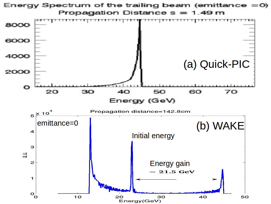
For the comparison of WAKE and Quick-PIC simulations, we consider a two bunch electron beam driver. The plasma and beam parameters for the simulations are shown in Table 1. The density of the cold background plasma in this case is taken to be giving . These parameters are similar to those chosen by An et al. An et al. (2010) except that the initial emittance of the beam is zero in our case. In both QuickPIC and WAKE simulations, the energy spectrum of the witness bunch peaks at approximately 44.5 GeV after propagating a distance of m (Fig. 2). Since the initial energy of the witness bunch is 23 GeV, the energy gain is approximately 21.5 GeV. Thus, the results of QuickPIC and WAKE simulations are in good agreement.
IV Effect of plasma temperature on electric field spike

It has earlier been reported that non-zero plasma temperature can suppress the electric field peak that forms behind the beam driver Lotov (2003). We study, using WAKE, the effect of non-zero plasma temperature on the electric field spike for the two electron bunch case. The plasma and beam parameters for the WAKE simulations correspond to two bunch experiments at FACET and are shown in Table 1.
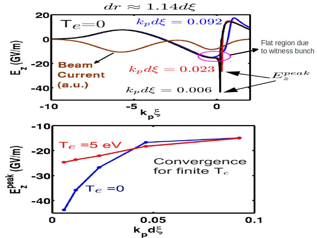
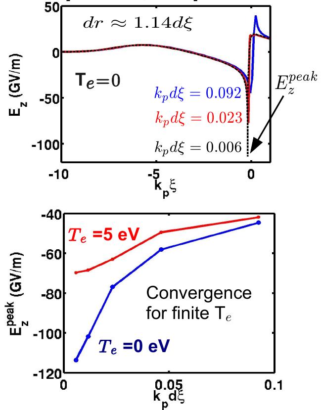
Figure 3 (top panel) shows profiles of the longitudinal electric field along the axis of the beam for several values of plasma temperature that would be expected in the experiments. It can be clearly seen that non-zero plasma temperature does not affect the longitudinal electric field except at the spike. Consistent with earlier studies Lotov (2003), the magnitude of the spike amplitude drops when the temperature is non-zero. In the bottom panel, we show the variation of with plasma temperature . As the temperature increases from zero to a small but finite value, drops sharply. The sharp drop is followed by a slow drop until eV at which value saturates. Essentially, the spike disappears.
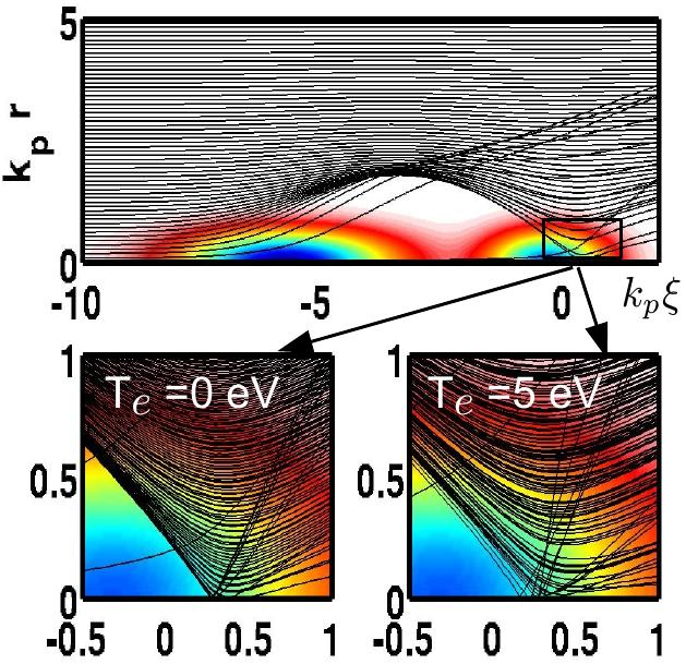
The drop in with can be understood by looking at the trajectories of plasma electrons, shown in Fig. 4. The plasma electrons expelled radially outward by the beam driver fall back and cross the axis behind the driver. The spike of the longitudinal electric field forms where these electrons cross the axis. It can be seen in the bottom two panels of Fig. 4 that warm electrons cross the axis over a region that is broader than the one in the case of cold electrons. This is because warm electrons have a distribution of initial velocities. The effect of plasma temperature on the trajectories of plasma electrons can be more clearly seen in case of a single bunch driver. Figure 5 shows the trajectories of plasma electrons for the case of a single bunch driver obtained by setting in the list of beam parameters shown in Table 1. The other parameters are the same as for the two bunch driver. For a single bunch driver, cold electrons cross the axis in a much narrower region as compared with the two bunch driver case. Again, non-zero plasma temperature spreads the trajectories of plasma electrons over a broader region on the axis. This makes the charge density smaller in the axis crossing region in the case of warm electrons, and thus, suppresses the electric field spike.

In the top panel of Fig. 3, the electric field profile has a flat region (indicated by an arrow) near the spike due to the beam load Tzoufras et al. (2008) of the witness bunch behind the driver bunch. The flat region has relatively uniform accelerating electric field and thus improves the quality of the accelerated electrons by reducing the energy spread. The parameters of the driver and witness bunch and distance between them can be tuned to optimize the flat region (magnitude of electric field and extent of the region) for a high quality accelerated beam. Although a major portion of the witness bunch sits and is accelerated in the flat region, a finite number of electrons (at and very close to the location of the spike) can be accelerated by the spike electric field. Since the magnitude of the spike electric field drops with increasing temperature, a natural question arises: How does the plasma temperature affect the energy gain and energy spread?
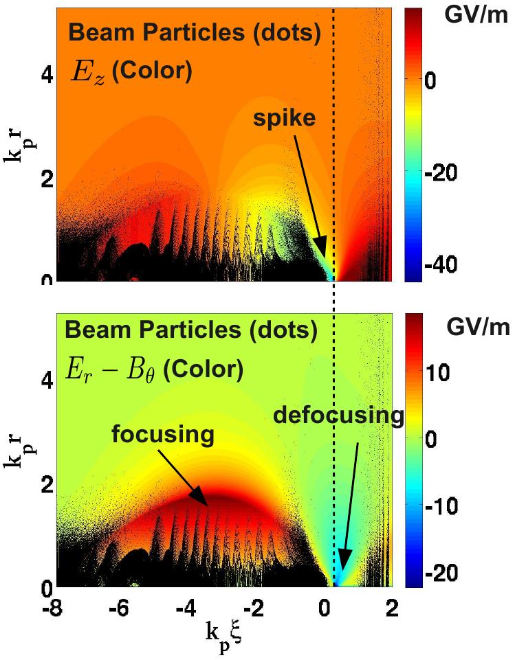
Figure 6 shows the energy spectrum of beam electrons after 1.14 meters of propagation for and eV. Based on the relatively uniform electric field GV/m in the flat region in Fig. 3, the expected energy gain after 1.14 m of propagation is GeV which is the same energy gain as obtained from WAKE simulation and shown in Fig. 6. The expected maximum energy gains by the peaks of the electric field spikes for and eV are Gev and GeV, respectively. However we do not see any such energy gains in Fig. 6. There is little difference in the two energy spectra. The reason for this is explained in Fig. 7. The location of the spike of the longitudinal electric field is indicated by an arrow in the top panel of Fig. 7. A dashed vertical line connecting the top and bottom panel shows that the radial electric field in the bottom panel is inward (towards the axis) and thus defocussing for electrons at the location of the field spike. This defocussing radial electric field expels the beam electrons at the location of the spike away from the axis. In Fig. 7, there are no beam electrons in the defocussing region, and therefore, the spike of the longitudinal electric field does not contribute to energy gain.

Although plasma temperature does not affect the energy gain and spread, it can effectively improve the numerical convergence of the electric field spike with grid size. The electric field spike has been shown to depend on the grid resolution in full PIC simulations using OSIRIS Lee et al. (2000). The amplitude of the spike increases as grid resolution is increased. We saw similar behavior of the spike in WAKE simulations, as shown in Fig. 8. The flat region in which the witness bunch sits does not depend on the grid size, however the peak of the electric field spike does depend on grid size. The bottom panel in Fig. 8 shows the dependence of on the grid size for and eV. For cold plasma, the value of does not seem to converge while it tends to converge to a finite value for eV. Similar behavior is observed for the case of a single bunch driver (), shown in Fig. 9. The reason for this behavior can be understood as follows. As long as the grid size is larger than the axis crossing region (confining charge) behind the electron beam driver, reducing the grid size will increase the charge density, and thus, the electric field at the spike. This is because the reduce grid volume still contain the same amount of charge. Once the grid size is comparable to the extent of the axis crossing region, the amplitude of the spike should converge to a finite value. For warm plasma, electrons cross the axis in a relatively broader region as compared to the cold plasma. This makes it possible to resolve the axis crossing region with a relatively large grid size.
V Conclusion
We upgraded the quasi-static code WAKE to include the capabilities of modeling the propagation of an electron (charged particle) beam driver through a warm background plasma in plasma wakefield acceleration. The code was benchmarked against (1) published 3D results from the full particle-in-cell code OSIRIS for a single bunch electron beam driver and (2) the 3D quasi-static code QuickPIC for two bunch electron scheme with parameters corresponding to experiments at FACET. For the two bunch scheme, the spike of the electric field which forms behind the driver bunch is suppressed for a range of values of the plasma temperature attainable in plasma wakefield experiments. This is because non-zero plasma temperature leads to the axis crossing of the plasma electrons over a broader region, decreasing the charge density and thus electric field of the spike. However, the suppression of spike does not affect the energy gain and energy spread of the accelerated electrons because the spike is co-located with a defocussing region. Due to the broadening of the axis crossing region of plasma electrons for non-zero plasma temperature, the electric field spike can be resolved with coarser grid as compared to the one required for cold plasma, thus improving the numerical convergence of the electric field spike with grid resolution.
Acknowledgements.
This work was supported by DoE grants DE SC0008491, DE SC0008316, DE FG02-92 ER40727, NSF ACI 1339893, ONR N000140911190 and DoE DESC0007970.References
- Chen et al. (1985) P. Chen, J. M. Dawson, R. W. Huff, and T. Katsouleas, Phys. Rev. Lett. 54, 693 (1985).
- Rosenzweig et al. (1991) J. B. Rosenzweig, B. Breizman, T. Katsouleas, and J. J. Su, Phys. Rev. A 44, R6189 (1991).
- Lu et al. (2006) W. Lu, C. Huang, M. Zhou, W. B. Mori, and T. Katsouleas, Phys. Rev. Lett. 96, 165002 (2006).
- Hogan et al. (2000) M. J. Hogan, R. Assmann, F. J. Decker, R. Iverson, P. Raimondi, S. Rokni, R. H. Siemann, D. Walz, D. Whittum, B. Blue, C. E. Clayton, E. Dodd, R. Hemker, C. Joshi, K. A. Marsh, W. B. Mori, S. Wang, T. Katsouleas, S. Lee, P. Muggli, P. Catravas, S. Chattopadhyay, E. Esarey, and W. P. Leemans, Phys. Plasmas 7, 2241 (2000).
- Blumenfeld et al. (2007) I. Blumenfeld, C. E. Clayton, F.-J. Decker, M. J. Hogan, C. Huang, R. Ischebeck, R. Iverson, C. Joshi, T. Katsouleas, N. Kirby, W. Lu, K. A. Marsh, W. B. Mori, P. Muggli, E. Oz, R. H. Siemann, D. Walz, and M. Zhou, Nature 445, 741 (2007).
- Hemker et al. (2000) R. G. Hemker, W. B. Mori, S. Lee, and T. Katsouleas, Phys. Rev. ST Accel. Beams 3, 061301 (2000).
- Martins et al. (2010) S. F. Martins, R. A. Fonseca, L. O. Silva, W. Lu, and W. B. Mori, Comp. Phys. Comm. 181, 869 (2010).
- Huang et al. (2006) C. Huang, V. Decyk, C. Ren, M. Zhou, W. Lu, W. Mori, J. Cooley, T. A. Jr., and T. Katsouleas, J. Comp. Phys. 217, 658 (2006).
- Mora and Antonsen (1997) P. Mora and T. M. Antonsen, Phys. Plasmas 4, 217 (1997).
- Lotov (2003) K. V. Lotov, Phys. Rev. ST Accel. Beams 6, 061301 (2003).
- Morshed, Antonsen, and Palastro (2010) S. Morshed, T. M. Antonsen, and J. P. Palastro, Phys. Plasmas 17, 063106 (2010).
- Coffey (1971) T. P. Coffey, Phys. Fluids 14 (1971).
- Katsouleas and Mori (1988) T. Katsouleas and W. B. Mori, Phys. Rev. Lett. 61, 90 (1988).
- Krall, Joyce, and Esarey (1991) J. Krall, G. Joyce, and E. Esarey, Phys. Rev. A 44, 6854 (1991).
- Lee et al. (2000) S. Lee, T. Katsouleas, R. Hemker, and W. B. Mori, Phys. Rev. E 61, 7014 (2000).
- Zeng et al. (2012) M. Zeng, A. Davidson, W. Lu, W. An, Z.-M. Sheng, and W. B. Mori, AIP Conf. Proc. 1507, 351 (2012).
- Hogan et al. (2010) M. J. Hogan, T. O. Raubenheimer, A. Seryi, P. Muggli, T. Katsouleas, C. Huang, W. Lu, W. An, K. A. Marsh, W. B. Mori, C. E. Clayton, and C. Joshi, New J. Phys. 12, 055030 (2010).
- An et al. (2010) W. An, W. Lu, C. Joshi, W. B. Mori, C. Huang, M. J. Hogan, S. F. Martins, and L. O. Silva, Advanced Accelerator Concepts: 14th Advanced Accelerator Concepts Workshop. AIP Conference Proceedings 1299, 472 (2010).
- (19) Figure provided by Weiming An .
- Tzoufras et al. (2008) M. Tzoufras, W. Lu, F. S. Tsung, C. Huang, W. B. Mori, T. Katsouleas, J. Vieira, R. A. Fonseca, and L. O. Silva, Phys. Rev. Lett. 101, 145002 (2008).
- Amatuni, Elbakian, and Sekhpossian (1992) A. T. Amatuni, S. S. Elbakian, and E. V. Sekhpossian, Particle Accelerators 36, 241 (1992).
- Esarey et al. (2007) E. Esarey, C. B. Schroeder, E. Cormier-Michel, B. A. Shadwick, C. G. R. Geddes, and W. P. Leemans, Phys. Plasmas 14, 056707 (2007).
- Floettmann (2003) K. Floettmann, Phys. Rev. ST Accel. Beams 6, 34202 (2003).
- Gholizadeh et al. (2011) R. Gholizadeh, T. Katsouleas, C. Huang, W. B. Mori, and P. Muggli, Phys. Rev. ST Accel. Beams 14, 021303 (2011).
- Katsouleas (1986) T. Katsouleas, Phys. Rev. A 33, 2056 (1986).
- Katsouleas et al. (1987) T. Katsouleas, S. Wilks, P. Chen, J. M. Dawson, and J. J. Su, Particle Accelerators 22, 81 (1987).
- Kirby et al. (2009) N. Kirby, I. Blumenfeld, C. E. Clayton, F. J. Decker, M. J. Hogan, C. Huang, R. Ischebeck, R. H. Iverson, C. Joshi, T. Katsouleas, W. Lu, K. A. Marsh, S. F. Martins, W. B. Mori, P. Muggli, E. Oz, R. H. Siemann, D. R. Walz, and M. Zhou, Phys. Rev. ST Accel. Beams 12, 051302 (2009).
- Lee and Cooper (1976) E. P. Lee and R. K. Cooper, Particle Accelerators 7, 83 (1976).
- Lotov (1996) K. V. Lotov, Phys. Plasmas 3, 2753 (1996).
- Muggli et al. (2010) P. Muggli, I. Blumenfeld, C. E. Clayton, F. J. Decker, M. J. Hogan, C. Huang, R. Ischebeck, R. H. Iverson, C. Joshi, T. Katsouleas, N. Kirby, W. Lu, K. A. Marsh, W. B. Mori, E. Oz, R. H. Siemann, D. R. Walz, and M. Zhou, New J. Phys. 12, 045022 (2010).
- Rosenzweig (1988) J. B. Rosenzweig, Phys. Rev. A 38, 3634 (1988).
- Su et al. (1987) J. J. Su, T. Katsouleas, J. M. Dawson, P. Chen, M. Jones, and R. Keinigs, IEEE Trans. Plasma Sci. 15, 192 (1987).
- Trines and Norreys (2006) R. M. G. M. Trines and P. A. Norreys, Phys. Plasmas 13, 123102 (2006).
- Wang et al. (2007) X. Wang, P.Muggli, T. Katsouleas, R. Ischebeck, and C. Joshi, Particle Accelerator Conference SLAC-PUB-13102 (2007).
- Wang et al. (2009) X. Wang, P.Muggli, T. Katsouleas, C. Joshi, W. B. Mori, R. Ischebeck, and M. J. Hogan, Phys. Rev. ST Accel. Beams 12, 51303 (2009).
- Yazdanpanah, Anvari, and Samimi (2009) . J. Yazdanpanah, A. Anvari, and J. Samimi, Phys. Plasmas 16, 023104 (2009).