Vertexing and Tracking Software at Belle II
Abstract:
Belle II is a factory experiment aiming to start physics data taking in 2017. It is currently being set up at the SuperKEKB accelerator at the KEK facility in Tsukuba (Japan), an asymmetric collider which aims to achieve an unprecedented instantaneous luminosity of . This forty-fold increase over predecessor experiments is achieved by employing a novel nano-beam scheme. Originally developed for the now-defunct SuperB experiment, this scheme allows a significant increase in luminosity at only modest increases of beam currents. Challenges for the vertex detector result from increased data and background rates. At full luminosity, physics data will be recorded at a rate of . The radiation-hard DEPFET-sensors of the innermost layer of the vertex detector will be read out employing a novel data-reduction scheme using selective detector read out based on online reconstruction of event data. Belle II uses a software framework in which data handling is unified between various data processing modules. In this way, tasks can be divided flexibly and the same software framework can be used for a diversity of tasks ranging from the high-level trigger to final processing of plots for publications. Tracking and vertexing modules are currently under development and we will discuss their features.
pacs:
29.40.Gx, 29.85.Ca, 29.85.-c1 Introduction
Our experimental knowledge of the flavor structure of the Standard Model is in large parts due to the -factories Belle and BaBar. Situated at the asymmetric colliders KEKB and PEP-II, respectively, they collected data throughout the first decade of the 2000s, confirming in great detail the CKM theory, and the related violation of the fundamental discrete symmetries , and [1]. Belle II is a successor to these experiments [2]. It employs the same concept of asymmetric collisions at the resonance which decays into two mesons , but compared to the predecessor experiments Belle II uses a slightly reduced beam momentum asymmetry. Typical travel distances of the mesons before their decays are . Belle II is an exploratory experiment aiming to test the predictions of the flavor sector of the Standard Model at unprecedented precision, thus probing new physics contributions well into the TeV mass range, given sufficient misalignment of the new physics flavor structure with that of the Standard Model [3]. The Belle II experiment is currently assembled at the SuperKEKB accelerator at the KEK facility in Tsukuba, Japan. The experiment is organized as an international collaboration of some 600 researchers and will start taking physics data in 2017, quickly integrating more luminosity than its predecessor experiments, then aiming for a total integrated luminosity accumulated over a period of approximately eight years.
The target luminosity of is approximately forty times larger than that of the predecessor facility KEKB. This is achieved by a novel nano-beam scheme for the interaction region supplemented by a two-fold increase in beam currents [4]. The increased luminosity leads to a corresponding increase in background levels, mainly QED backgrounds (which scale proportionally to luminosity), and in-beam scattering (Touschek effect, due to stronger focussing). Other machine backgrounds only scale as the beam current.
2 The Belle II detector
The Belle II detector is an upgrade of the Belle detector: it is housed in the same structure, reusing the spectrometer magnet. The design aimed for performance comparable to the performance of the Belle detector in spite of the increased background levels expected at the higher-luminosity accelerator. Where most parts of the detector were refined in various ways, two major new components were introduced in the design: a pixel vertex detector based on the DEPFET technology very close to the interaction point which is capable of withstanding the increased radiation levels while providing excellent resolution, and a complete overhaul of the particle identification detectors which are of Cherenkov imaging type. Additionally, the beam pipe is replaced with a smaller, thinner device, which allows installing the innermost layer of the vertex detector at a distance of only from the interaction point.
The components of the Belle II vertex detector are discussed in detail in Peter Kodys’s [5], Michael Schnell’s [6] and Lorenzo Vitale’s [7] contributions to this conference, so we will restrict ourselves to an executive summary.
Belle II is designed for detecting and reconstructing particle trajectories for transverse momenta exceeding while providing excellent momentum resolution all the way up to at the physical limit which is half the center of mass energy . The vertex detector consists of six layers of silicon detectors, situated at radial distances from the interaction point between and . It is surrounded by a wire-chamber that extends up to a radius of .
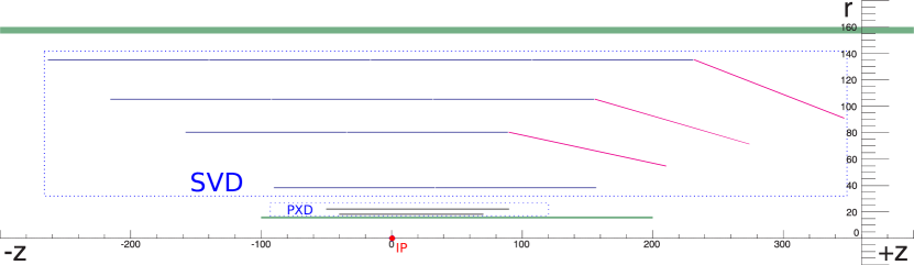
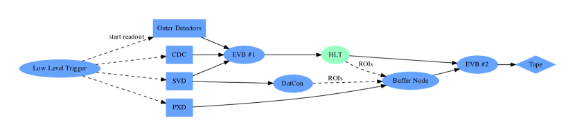
The vertex detector itself consists of two subdetectors, cf. Fig. 1. The two innermost layers are built from DEPFET-type active sensors with pixel readout [8], able to withstand the high radiation levels. These semiconductor detectors are thinned to in the active area corresponding to a radiation length of . The surrounding four layers are built using double-sided silicon strip detectors of thickness , read out using APV25 chips [9]. Readout has to deal with the long integration times of the DEPFET sensors () which is comparable to the physics trigger rate (). Given the expected occupancy in the range of , full readout at every trigger would lead to a data rate of for the pixel layers alone, exceeding the amount of data collected by the remainder of Belle II by an order of magnitude. In order to reduce this to something supportable, an online data reduction scheme has to be put in place. This is implemented by a two-level event building/high-level triggering scheme, illustrated in Fig. 2. Upon occurence of a low-level trigger signal, all subdetectors besides the pixel detector are read out, events are built and fed to the high-level trigger. Simultaneously, the pixel-detector data is read out and stored on a buffer node [10]. The high-level trigger performs a full reconstruction of the event sans pixel data. Reconstructed tracks are then extrapolated back to the pixel layers, where the vicinities of the estimated crossing points define regions-of-interest which are read from the buffer node and added to the event in a second event-building step [11]. As an alternative, an FPGA-based implementation of this region-of-interest definition is implemented on dedicated readout hardware of the silicon strip detector. This approach was discussed in another contribution to this conference [6]. In order to recover tracks with very low transverse momenta, additionally pixel data corresponding to very large ionisation is recorded irrespective of whether it can be associated with a region-of-interest. In this way a ten-fold reduction of the amount of data recorded can be achieved.
The wire chamber construction was recently completed. The detector is now being tested and first calibrations using cosmic rays are being performed. It has a total of 14k sense wires and 42k field wires, distributed over the volume. The signal wires are organized in 56 radial layers which are subdivided into nine super-layers, of which five have wires along the direction of the magnetic field (“axial wires”) and four are inclined in order to determine the track coordinates in the direction of the field (“stereo wires”) [12].
3 The Belle II software framework
Belle II unifies all data processing tasks in a single software package, basf2 [13, 14, 15, 16] which runs on standard Linux systems. This package consists of a flexible framework of individual modules which process the data. The modules are organized in a user-defined chain. Each module can read data provided by the preceding modules via the so-called data store, and it can also add additional data to the data store. Special modules can read data from disk or from detectors, or send and receive data over the network. As an illustration of this, consider a track-finding module: it will read detector hits from the data store and write track candidates to the data store. If it processes MC data, it may also read a relation between the hits and MC truth information, and use this to establish a relation between track candidates and the particles created during the simulation. These track candidates can then be processed by a track fitting module.
Data store contents can be serialized or read at any point in the chain. This functionality is used in several ways. Besides storage of the processed data, this allows distributing the data over multiple cores or networked hosts transparently, and it allows an arbitrary splitting of the taks between different computer jobs. E.g. an alternative implementation of a module can be tested without repeating any of the work done before: one processes the chain up to, but not including, the module under test, and stores the result to disk. Now any change to the module can be tested immediately, by reading the data from disk and processing the chain starting from the module under inspection.
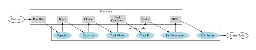
The design is driven in particular by the needs of the high-level trigger of the Belle II experiment, which uses a networked computing farm running the full reconstruction software, and which plays an essential role in the readout of the pixel vertex detector, as explained above. As a complement to Fig. 2, we show as an example of such a processing path the sequence of modules used in a recent beam test where pixel and silicon strip layers as well as the full readout architecture including the high-level trigger were employed [11]. The sequence shown in Fig. 3 shows how the incoming raw detector data is sequentially processed to yield the regions-of-interest, sent to the buffer node by the “ROI Sender” module in the end. In the test-beam experiment, this chain ran on the high-level trigger node, indicated by HLT in Fig. 2.
4 Tracking and vertexing software
Physics analysis in Belle II will concern itself with the ongoings near the interaction point, the objects of interest in a typical analysis are the decay products of the and mesons produced in the initial reactions. The mesons decay in close vicinity of a few hundred to the interaction point which in the employed nanobeam scheme is itself very well-defined. In this vein, the reconstructed objects used for analysis are parameterized in the vicinity of the interaction point. In the mDST data format used for analysis, track parameters are stored in a perigee helix parametrization together with information from particle identification. objects which decay at appreciable distances from the interaction point are reconstructed from their decay tracks before being stored in the mDST files. Photons and are stored using the information from the respective detectors. This way, the original decay vertices can be reconstructed efficiently on the level of physics analysis and file sizes are minimized. In the following we will discuss the reconstruction steps that lead to the mDST data.
4.1 Track finding
Track candidates are identified independently in the vertex detector and the wire chamber. In the vertex detector, a cellular-automaton algorithm is used to cope with the potentially large combinatorics, especially in the presence of background [17, 11]. Adjacent pairs of hits are combined into what is called a cell. If two different cells share a hit, they become neighbors in the space of the cellular automaton. The cellular automaton is then evolved where the cell state develops according to the number of geometrically allowed neighbors and the state of the neighbors. From this procedure results a set of possible combinations of hits, where the same hits may appear in several combinations. A Hopfield network, trained with Monte Carlo simulations, is then used to extract the best non-overlapping set of track candidates, which are forwarded to the track fit.
In the wire chamber, besides an adapted version of the track finding algorithm used in the predecessor experiment Belle, two newly developed track finders are used: a global track finder based on Legendre transformations which is limited to tracks emitted in the vicinity of the interaction point, and a local track finder which uses a cellular automaton to follow tracks through the wire chamber volume.
After track fitting, compatible tracks from both subdetectors are merged, and tracks for which no compatible track in the other subdetector could be found are extrapolated, looking for unassociated hits which can be added. The stored tracks are updated to reflect these operations.
4.2 Track fitting
The track candidates are then fitted using a largely overhauled version of the Genfit track fitting package [18, 19]. On the high-level trigger, the default tracking algorithm is the usual Kalman fitter [20]. On the other hand, in physics analysis the adaptive deterministic annealing algorithm [21] is used. It is an extension of the Kalman fitter that uses an annealing procedure to reject background-induced hits that were mistakenly added by the track finding algorithms, and it can also resolve left/right ambiguities in the wire chamber measurements. For the purpose of alignment, tracks are reconstructed with the General Broken Lines algorithm [22], which is a global formulation of the Kalman fit with a discretized model of material. The alignment procedure is described in another contribution to this conference [23].
The fitted tracks are extrapolated outwards to the various particle identification detectors (Cherenkov detectors, electromagnetic calorimeter, and muon/ id chambers). The ionization deposits in the silicon detector layers and the wire chamber are also used for -based particle identification. The Cherenkov detector places stringent limits on the precision of the time-of-flight determination which is evaluated during the track fit based on the individual segments between the individual hits. The tracks are extrapolated towards the interaction point, and the helix information in the perigee parametrization is stored in the mDST.
4.3 Vertex finding and fitting
In order to reconstruct type decays, all negative tracks are paired up with all positive tracks, and a vertex fit is performed using the standard Kalman fit implemented in the RAVE package [24]. If a vertex that is separated from the interaction region could be reconstructed by this procedure, a object is added to the mDST. Physics analysis then uses the reconstructed tracks, the s and additional calorimeter and objects stored in the mDSTs to recover the mesons. The vertex is reconstructed using either the RAVE package or the vertexing tool adapted from the Belle experiment, KFIT. As a promising new development, the increased data sample of the Belle II experiment allows to perform with unprecedented statistics analyses where all decay particles of at least one of the , mesons are reconstructed, and thus the complete event (up to invisible particles from one of the decays) can be reconstructed. The small size of the beam crossing region allows additional strong constraints as the transverse momentum of the mesons is strongly correlated with the observed displacement from the interaction point.
5 Outlook
The Belle II experiment will begin its physics data taking in 2017. Owing to its significantly increased luminosity, it will allow great improvements in measurements that were thus far limited by statistics. New developments such as the full-event reconstruction will allow to put stringent limits on invisible decays or decays with only one charged particle. Not discussed in this proceeding, but worth mentioning are also the large samples of and events whose analysis will also benefit from Belle II’s advanced vertexing capabilities.
References
- Bevan et al. [2014] A.J. Bevan et al. The Physics of the B Factories. 2014 arXiv:1406.6311.
- Abe et al. [2010] T. Abe et al. Belle II Technical Design Report. 2010 arXiv:1011.0352.
- Aushev et al. [2010] T. Aushev et al. Physics at Super B Factory. 2010 arXiv:1002.5012.
- Ohnishi et al. [2013] Y. Ohnishi et al. Accelerator design at SuperKEKB. PTEP, 2013:03A011, 2013.
- [5] P. Kodys. Cluster-shape Based Improvement of Spatial Resolution for the Belle II DEPFET Pixel Detector. These proceedings \posPoS(Vertex2014)049.
- [6] M. Schnell. Belle II PXD Detector. These proceedings \posPoS(Vertex2014)016.
- [7] L. Vitale. Belle II SVD Detector. These proceedings \posPoS(Vertex2014)017.
- Alonso et al. [2013] O. Alonso et al. DEPFET active pixel detectors for a future linear collider. IEEE Transactions on Nuclear Science, 60(2):1457–1465, April 2013 arXiv:1212.2160.
- Friedl et al. [2013] M. Friedl et al. The Belle II Silicon Vertex Detector. Nucl.Instrum.Meth., A732:83–86, 2013.
- Geßler et al. [2014] T. Geßler et al. The ONSEN Data Reduction System for the Belle II Pixel Detector. 2014 arXiv:1406.4028.
- Bilka et al. [2014] T. Bilka et al. Demonstrator of the Belle II Online Tracking and Pixel Data Reduction on the High Level Trigger System. 2014 arXiv:1406.4955. Submitted to IEEE Trans. Nucl. Sci.
- Taniguchi et al. [2013] N. Taniguchi et al. All-in-one readout electronics for the Belle-II Central Drift Chamber. Nucl.Instrum.Meth., A732:540–542, 2013.
- Itoh et al. [2012] R. Itoh et al. Implementation of parallel processing in the basf2 framework for Belle II. J.Phys.Conf.Ser., 396:022026, 2012.
- Lee et al. [2011] S. Lee et al. Development of high level trigger software for Belle II at SuperKEKB. J.Phys.Conf.Ser., 331:022015, 2011.
- Moll [2011] A. Moll. The software framework of the Belle II experiment. J.Phys.Conf.Ser., 331:032024, 2011.
- [16] D.Y. Kim. The software library of the Belle II experiment. To appear in proceedings of the 37th International Conference on High Energy Physics (ICHEP 2014).
- Frühwirth et al. [2013] R. Frühwirth et al. Track finding in silicon trackers with a small number of layers. Nucl.Instrum.Meth., A732:95–98, 2013.
- Höppner et al. [2010] C. Höppner et al. A Novel Generic Framework for Track Fitting in Complex Detector Systems. Nucl.Instrum.Meth., A620:518–525, 2010 arXiv:0911.1008.
- Rauch et al. [2014] J. Rauch et al. GENFIT - a Generic Track-Fitting Toolkit. 2014 arXiv:1410.3698.
- Frühwirth [1987] R. Frühwirth. Application of Kalman filtering to track and vertex fitting. Nucl.Instrum.Meth., A262:444–450, 1987.
- Frühwirth et al. [2006] R. Frühwirth et al. Application of adaptive filters to track finding. Nucl.Instrum.Meth., A559:162–166, 2006.
- Kleinwort [2012] C. Kleinwort. General Broken Lines as advanced track fitting method. Nucl.Instrum.Meth., A673:107–110, 2012 arXiv:1201.4320.
- [23] T. Bilka. Alignment of the Belle II Vertex Detector. These proceedings \posPoS(Vertex2014)048.
- Waltenberger [2011] W. Waltenberger. RAVE: A detector-independent toolkit to reconstruct vertices. IEEE Trans.Nucl.Sci., 58:434–444, 2011.