Coherent Control of a Nitrogen-Vacancy Center Spin Ensemble with a Diamond Mechanical Resonator
Abstract
Coherent control of the nitrogen-vacancy (NV) center in diamond’s triplet spin state has traditionally been accomplished with resonant ac magnetic fields under the constraint of the magnetic dipole selection rule, which forbids direct control of the spin transition. We show that high-frequency stress resonant with the spin state splitting can coherently control NV center spins within this subspace. Using a bulk-mode mechanical microresonator fabricated from single-crystal diamond, we apply intense ac stress to the diamond substrate and observe mechanically driven Rabi oscillations between the and states of an NV center spin ensemble. Additionally, we measure the inhomogeneous spin dephasing time () of the spin ensemble using a mechanical Ramsey sequence and compare it to the dephasing times measured with a magnetic Ramsey sequence for each of the three spin qubit combinations available within the NV center ground state. These results demonstrate coherent spin driving with a mechanical resonator and could enable the creation of a phase-sensitive -system within the NV center ground state.
Spin-based quantum systems typically rely on resonant magnetic fields to drive coherent transitions between different spin states. Although such magnetic driving has been effective, developing alternative modes of control opens new routes for coupling disparate quantum states to form a hybrid quantum system Soykal et al. (2011). New techniques for manipulating a spin state also naturally extend to new sensing capabilities and an enhanced understanding of how spin systems interact with their environment.
The spin triplet ground state of the nitrogen-vacancy (NV) center in diamond represents a coherently addressable paramagnetic defect confined within a largely non-magnetic carbon lattice. This creates an excellent laboratory for studying how spin-based quantum systems interact with their environment Hanson et al. (2008) and for exploring new methods of quantum control Dobrovitski et al. (2013). Studies have shown that NV center spins can be controlled magnetically Jelezko et al. (2004), optically Togan et al. (2011); Yale et al. (2013), electrically Dolde et al. (2011), and mechanically MacQuarrie et al. (2013); Teissier et al. (2014); Ovartchaiyapong et al. (2014). The direct spin-phonon coupling that enables mechanical spin control mediated by lattice strain has prompted the experimental development of single-crystal diamond mechanical resonators Burek et al. (2013); MacQuarrie et al. (2013); Teissier et al. (2014); Ovartchaiyapong et al. (2014) and motivated theoretical calculations showing that this interaction could enable spin squeezing Bennett et al. (2013) and mechanical resonator cooling Kepesidis et al. (2013). Nonetheless, coherent Rabi driving of NV center spins with a mechanical resonator has not been previously demonstrated. Furthermore, understanding the dynamics of mechanical driving in spin ensembles could have applications in NV center-based sensing and quantum optomechanics where spin-phonon interactions can be enhanced by using a large number of spins.
Here we use a mechanical microresonator to apply a large amplitude ac stress to a single crystal diamond. Building on recent spectroscopy experiments MacQuarrie et al. (2013), we tune the frequency of this stress wave into resonance with the spin transition to mechanically drive Rabi oscillations of an NV center spin ensemble. Using this capability, we measure the inhomogeneous dephasing time for an ensemble of mechanically controlled NV center spin qubits to be s and compare this result to for magnetically driven qubits constructed from the same NV center ensemble. We find that the mechanically driven , qubit coherence is similar to that of a magnetically driven , qubit, and these , qubits dephase twice as quickly as magnetically driven , or , qubits.
NV centers couple to mechanical stress ( and ) and magnetic fields ( and ) through their ground-state spin Hamiltonian (shown schematically in Fig. 1a)
| (1) |
where GHz is the zero-field splitting, MHz/G is the gyromagnetic ratio, MHz/MPa and MHz/MPa are the perpendicular and axial stress coupling constants Ovartchaiyapong et al. (2014); SI , MHz and MHz are the hyperfine parameters Doherty et al. (2012); Smeltzer et al. (2009); Steiner et al. (2010), and , , (, , ) are the , , and components of the electronic (nuclear) spin-1 operator. The NV center symmetry axis defines the -axis of our coordinate system as depicted in Fig. 1b. In the Supplementary Information (SI), we use the stiffness matrix for diamond to calculate and from the strain coupling constants GHz/strain and GHz/strain measured by Ovartchaiyapong, et al SI ; Ovartchaiyapong et al. (2014). Non-axial stress couples the and spin states, enabling coherent control of the magnetically-forbidden spin transition and providing direct access to the , spin qubit. This qubit combination has recently become a topic of interest because it is isolated from thermal fluctuations Fang et al. (2013) and can make a more sensitive magnetometer than either the , or , qubit Fang et al. (2013); Mamin et al. (2014).
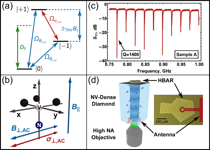 |
In this work, we use two devices, both fabricated from type IIa, “optical grade” diamonds purchased from Element Six. These samples are specified to contain fewer than 1 ppm nitrogen impurities, and each contained a native NV ensemble as received. The first sample, Sample A, has an NV center density of NVs/m3, while Sample B has a density of NVs/m3. To generate the large amplitude, high-frequency stress waves needed for coherent mechanical control, we fabricate high-overtone bulk acoustic resonators (HBARs) that use these single crystal diamonds as resonant cavities. The HBARs used for these measurements consist of either a m (Sample A) or a m (Sample B) zinc oxide (ZnO) piezoelectric film sandwiched between a patterned Al electrode and a Ti/Pt ground plane, all sputtered on one face of the diamond substrate. By driving an HBAR with a high-frequency voltage, we transduce stress waves inside the diamond. The diamond then acts as an acoustic Fabry-Pérot cavity to create standing wave resonances. Fig. 1c shows a network analyzer measurement of the microwave power reflected () from the Sample A HBAR with the MHz mode () used in these experiments indicated. Measurements on Sample B used a MHz resonance with a of . On the reverse side of each diamond, we fabricate a loop antenna that produces gigahertz-frequency magnetic fields for conventional magnetic spin control. Fig. 1d depicts a schematic version of the resulting device.
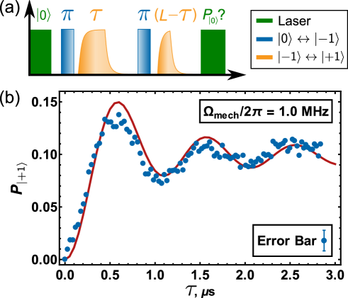
To perform mechanically driven spin coherence measurements, we first tune the axial magnetic field to bring the spins into resonance with a high-frequency stress wave as described in Ref. MacQuarrie et al. (2013). At this resonant , we mechanically drive Rabi oscillations of the , qubit. Fig. 2a shows the pulse sequence used to drive Rabi oscillations in the relatively low modes of Sample A. To initialize the NV center spins, we first optically polarize into and then transfer the spin population from to with a magnetic -pulse. Next, we apply a mechanical Rabi pulse of length that is resonant with the spin transition. To read out the spin signal, a second magnetic -pulse shuttles the population in to . Fluorescence measurement of the state population reveals how much spin population was transferred to according to the relation con . In order to maintain a constant average power to the device, we apply a second mechanical pulse at each data point of length where is the length of the longest Rabi pulse. This pulse comes before fluorescence read out but does not affect our measurement since the spin population we detect has left the , subspace. Fig. 2b shows mechanically driven Rabi oscillations as measured on Sample A for dBm of input power to the HBAR.
The damping observed in Fig. 2b arises from a combination of spin dephasing from magnetic bath noise and dephasing derived from spatial variations in the amplitude of the stress standing wave within the spin ensemble. NV centers near an anti-node of the stress wave feel a larger Rabi frequency than NV centers near a node. The finite collection volume of our confocal microscope necessitates measuring a distribution of coupling strengths, which causes the measured spin signal to dephase. To account for both of these dephasing sources, we model the data in Fig. 2b with the spatially-weighted average
| (2) |
where the factor of arises because we drive only one of the unpolarized nuclear spin sublevels, is the mechanical driving field, is the wavelength of the stress standing wave, and represents a Gaussian approximation to the microscope point spread function (PSF) with a FWHM that grows linearly with the depth of focus inside the diamond as described in Ref. MacQuarrie et al. (2013). We assume resonant driving and include quasi-static spin bath noise as a random detuning drawn from a Gaussian distribution with a standard deviation Aiello et al. (2013). The mechanical Ramsey measurement presented below sets s in the , subspace. With the parameters MHz, m, and m as inputs, we average iterations of the simulation to produce the model curve in Fig. 2b, which is not a fit to the experimental data.
 |
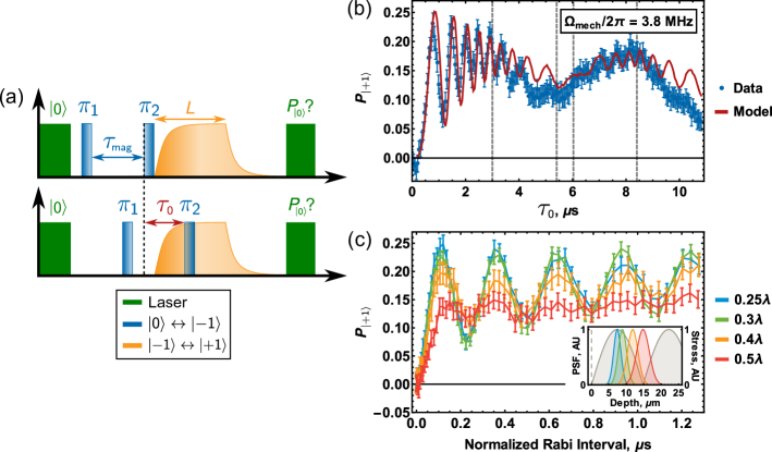
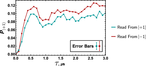
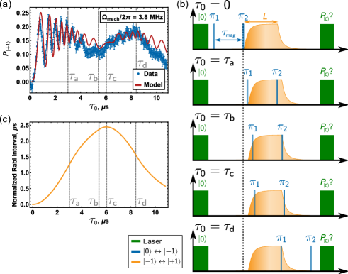
For devices with -factors substantially larger than Sample A, we find a standard Rabi pulse sequence is not effective. In these devices, the large bandwidth of short microwave pulses reduces their spectral precision, which in turn distorts the coupling between the mechanical resonator and its microwave drive. This becomes important in the higher resonance of Sample B. To control this effect, we pulse the stress wave for a fixed duration at each data point. Because the stress wave only affects spins in the , subspace, a pair of short ( ns) magnetic -pulses separated by a fixed interval controls the length of time the mechanical driving field is active. By sweeping this magnetic pulse pair through the mechanical pulse as shown in Fig. 3a, we measure mechanically driven Rabi oscillations in the , subspace. For dBm of input power, the mechanical driving field is MHz, which substantially exceeds the dephasing rate SI .
Fig. 3b shows a Rabi measurement using this protocol with the notable transition points in the sweep labeled and described in the figure caption. The model curve in Fig. 3b is the average solution of the Schrödinger equation for the spin population in after being driven by a segment of the mechanical pulse. We model the mechanical pulse with the functions for ring-up and for ring-down where and Seibert (985). As before, the model – which is not a fit to the data – accounts for driving field inhomogeneities by applying a spatially-weighted average over an approximated optical PSF and includes quasi-static magnetic bath noise through a randomized detuning. The SI provides additional details on the pulse sequence and model SI .
For the measurement shown, s where s. As such, the critical delay s corresponds to the largest mechanical pulse area enclosed between the two magnetic -pulses. To either side of this time step, the pulse area decreases at roughly the same rate. The asymmetry in the data about this point arises because for the mechanical pulse amplitude and thus instantaneous driving field is higher than when . This larger instantaneous driving field offers the spins better protection from magnetic bath noise as evinced by the larger amplitude Rabi oscillations. Our model correctly reproduces this asymmetry, demonstrating the possibility of using a mechanical driving field to achieve continuous dynamical decoupling of an NV center spin from a spin bath Xu et al. (2012).
By modeling the resonator ringing as described above, we can convert the mechanical pulse area between the two magnetic pulses into the “square-pulse” units typically used in magnetic Rabi measurements. Fig. 3c shows mechanical Rabi oscillations plotted as a function of this normalized Rabi interval for measurements taken at several depths inside the diamond substrate. As expected, the oscillations dephase faster near a node in the stress wave due to driving field inhomogeneities within the ensemble. Near the antinode, however, the relative uniformity of the stress wave mitigates this depth-dependence and, thus, the dephasing from driving field inhomogeneities.
 |
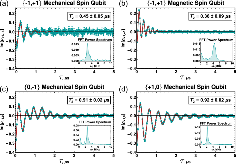
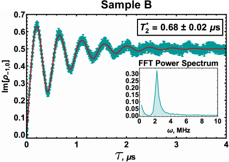
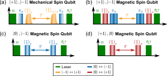
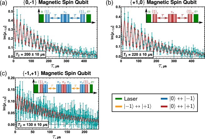
The more traditional Rabi pulse protocol used for Sample A provides a direct means to implement conventional pulse sequences. From the data in Fig. 2b, we extract the -pulse time and proceed to measure of Sample A with a mechanical Ramsey pulse sequence. Fig. 4 shows the result of this measurement along with Ramsey measurements of for magnetically driven , ; , ; and , qubits. Details on the pulse sequences used for each of these measurements are provided in the SI SI . Although selection rules forbid direct magnetic control of the transition, magnetic control of the , qubit can be accomplished indirectly by using either double-quantum pulses Mamin et al. (2014) or multi-pulse sequences Huang et al. (2011). Both of these alternatives use the state as a waypoint in the transition. To control the , qubit magnetically, we employ the multipulse sequence described in the SI SI .
 |
We fit the three magnetically driven Ramsey measurements to the function
| (3) |
where represents a detuning in the driving field, the amplitudes (, , ) allow for partial polarization of the nuclear sublevels, the constant phases (, , ) account for pulse phasing errors, and for the magnetically driven , qubit. Since the mechanical driving field ( MHz) does not overcome the hyperfine spacing ( MHz in the , subspace), it drives only one of the nitrogen nuclear spin sublevels. Therefore, we fit our mechanical Ramsey data to the function
| (4) |
where MHz describes an experimentally introduced phase that accumulates at to visualize the decay envelope SI . Our fitting procedure varies , , , and as free parameters. Since we measure the coherence of a spin ensemble, we extract from an exponentially decaying envelope rather than from the Gaussian decay expected for a single NV center Dobrovitski et al. (2008). Fig. 4 displays the values of extracted from these fits, and the figure caption lists the measured detunings .
The inset within each plot depicts a Fourier power spectrum of the corresponding data. For the magnetic qubits, the Fourier spectra show one peak at corresponding to the nuclear spin state. The magnetic , () qubit also shows a second peak with roughly twice the amplitude at () that represents nearly superposed peaks from the and nuclear states. For the magnetic , qubit, this peak appears at . The Fourier spectrum of the mechanical , qubit shows only one peak at because the mechanical driving field drives only one nuclear sublevel.
For the , qubit, we find that measured mechanically ( s) agrees well with measured magnetically ( s) where the uncertainties equal the square root of the variance in the fitting parameter. The , and , qubits have dephasing times s and s, respectively—approximately twice as long as that of the , qubit. This agrees with previous measurements performed on a single NV center in low magnetic field Huang et al. (2011); Fang et al. (2013). This reduced coherence time does not diminish the , qubit’s metrological utility because this qubit accumulates phase twice as fast as the longer-lived , and , qubits, thus reducing the integration time necessary to detect an identical signal Fang et al. (2013); Mamin et al. (2014). Additionally, pulsed dynamical decoupling sequences could be implemented in improved devices that take advantage of an anomalous decoherence effect unique to the , qubit. This effect can make the spin coherence of the , qubit longer than the spin coherence of either the , or the , qubit decoupled under an equivalent protocol Huang et al. (2011).
A number of engineering improvements can improve the performance of our devices. First, we expect additional refinements in device fabrication to increase the of our devices, which could provide at least a factor of enhancement in the mechanical driving field Sorokin et al. (2013). Also, working in higher electronic purity diamond will dramatically reduce spin bath induced dephasing, and working with either a single spin or a plane of NV centers would remove dephasing from driving field inhomogeneities. Taken together, these advances can unlock high fidelity quantum control of a mechanically driven qubit.
Our results demonstrate coherent control of all three ground state spin transitions. By simultaneously driving the and transitions magnetically and the transition mechanically, a -system in which all three states are coupled by a closed-loop interaction contour can be created within the NV center ground state. Such a system requires at least one parity non-conserving driving field, making -systems an uncommon extension of the more typical -system, which has been well explored in NV centers Hemmer et al. (2001); Santori et al. (2006a, b); Togan et al. (2011); Acosta et al. (2013); Yale et al. (2013). In a -system, driving field amplitudes and detunings balance to enable phenomena such as coherent population trapping Santori et al. (2006a, b) and electromagnetically induced transparency Hemmer et al. (2001); Acosta et al. (2013). In a -system, similar phenomena occur but with an additional sensitivity to the relative phases of the driving fields Buckle et al. (1986); Shahriar and Hemmer (1990); Kosachiov et al. (1992). Implementing an NV center -system could, for instance, create a phase induced transparency where the phase of a magnetic driving field tunes the absorption of the mechanical driving field. Such a system could have value in NV center optomechanics experiments as a phase-controlled switch to rapidly gate spin-phonon interactions. Another application could be measuring the relative phase of a resonating mechanical proof mass in an inertial sensor.
In summary, we use a high-frequency mechanical resonator to drive coherent Rabi oscillations of an NV center spin ensemble with driving fields up to MHz. This enabled a comparison of the inhomogeneous dephasing time of a mechanically driven , qubit with that of magnetically driven , ; , ; and , qubits. We found that, for both mechanical and magnetic driving, the , qubit dephases twice as fast as the , and , qubits. These results establish the possibility of creating a phase-sensitive -system within the NV center ground state, which could have applications in metrology, optomechanics, and quantum control.
I Acknowledgments
Research support was provided by the Office of Naval Research (ONR). ERM received support from the Department of Energy Office of Science Graduate Fellowship Program (DOE SCGF), made possible in part by the American Recovery and Reinvestment Act of 2009, administered by ORISE-ORAU under contract no. DE-AC05-06OR23100. Device fabrication was performed in part at the Cornell NanoScale Science and Technology Facility, a member of the National Nanotechnology Infrastructure Network, which is supported by the National Science Foundation (Grant ECCS-0335765), and at the Cornell Center for Materials Research Shared Facilities which are supported through the NSF MRSEC program (DMR-1120296).
II Supplementary Information
III NV Center Stress Coupling
Ovartchaiyapong, et al measured the NV center strain coupling to be GHz/strain and GHz/strain for perpendicular and axial strain, respectively Ovartchaiyapong et al. (2014). Since our mechanical resonator generates acoustic waves by applying a pressure to one face of the diamond crystal, we choose to work in units of stress. To convert the measured constants from strain to stress, we first rotate the measured couplings from the coordinate system defined by the NV center to the lattice coordinates. We then use the stiffness matrix for diamond Irgens (2008)
| (5) |
to convert strain/GHz into GPa/GHz (stress/GHz). The elastic constants are given in Table 1. Finally, we rotate back into the coordinates of the NV center to find the stress coupling constants MHz/MPa and MHz/MPa used in the main text.
| GPa | GPa | GPa |
IV Mechanical Rabi Measurements
IV.1 Readout Through
As a control, we performed a second type of Rabi measurement. In this alternative pulse sequence, after optically pumping the NV center into we once again apply a magnetic -pulse to resonantly move the population from to . We then pulse the resonant mechanical driving field for a length to drive the transition. Finally, we use a magnetic adiabatic passage to robustly transfer the population that was driven into to where we read out the spin state optically. This differs from the Rabi measurement presented in the main text in that we extract population from , not , for optical readout.
Fig. 5 shows the results of this measurement plotted alongside a mechanically driven Rabi measurement that uses a magnetic adiabatic passage to transfer population from to after the mechanical Rabi pulse. Both of these measurements were done on Sample A. As expected, the results are nearly identical. The difference in amplitudes comes from fidelity differences between the and magnetic pulses.
 |
IV.2 Mechanical Rabi Sequence for Sample B
Fig. 6a shows the mechanical Rabi oscillations plotted in Fig. 3b of the main text. This measurement was taken by sweeping a pair of magnetic -pulses through a fixed-length mechanical pulse. To further elucidate this pulse sequence, Fig. 6b provides a snapshot of the pulse sequence at each of the notable points indicated by dashed lines in Fig. 6a and described in the figure caption.
We model the ringing of a normalized mechanical driving field with the functions for ring-up and for ring-down where and Seibert (985). These functions allow us to compute the mechanical pulse area enclosed between the two magnetic -pulses for each value of . Fig. 6b plots this normalized Rabi interval as a function of .
 |
IV.3 Mechanical Rabi Model for Sample B
To fit the mechanical Rabi data shown in Fig. 3b of the main text, we solve the Schrödinger equation to find the population in after applying the relevant portion of an s mechanical pulse. We use the Hamiltonian
| (6) |
when the resonator is ringing up and the Hamiltonian
| (7) |
when the resonator is ringing down. Quasi-static magnetic bath noise takes the form of a randomized detuning drawn from a Gaussian distribution with a standard deviation Aiello et al. (2013). The magnetic Ramsey measurement shown in Fig. 7 sets s.
 |
Defining the result of this computation as the function , we then perform a spatially-weighted average over the point spread function (PSF) of our confocal microscope to account for spatial inhomogeneities in our mechanical driving field. The resulting signal takes the form
| (8) |
where accounts for partial polarization of the nuclear spin sublevel, is the mechanical driving field, is the wavelength of the stress wave, and describes a Gaussian approximation to a PSF centered at the focal depth with a depth dependent FWHM as described in Ref. MacQuarrie et al. (2013). To produce the model curve in Fig. 3b of the main text, we used the parameters MHz, m, (as measured via mechanically driven spin resonance), and m. The simulation was repeated times, and these results were averaged to produce the final curve.
V Ramsey Measurements
V.1 Ramsey Pulse Sequences
Fig. 8 shows the pulse sequences used for the Ramsey measurements presented in the main text. To eliminate experimental artifacts, we modified the typical Ramsey measurement to include a second measurement for each data point. We first execute the typical —— Ramsey sequence. Immediately afterward, we perform a —— sequence. The difference of these two measurements equals twice the imaginary portion of the qubit’s coherence (, ). We further modify the Ramsey sequence for the mechanically driven qubit by advancing the phase of the second -pulse by . This extra phase shift introduces a known periodicity to the measurement that aids visualization of the decay envelope.
V.2 Ramsey Measurement Normalization
Two measurements were used to normalize the spin contrast for the magnetic Ramsey measurements in the , and , subspaces. The maximum spin signal is measured by optically pumping the NV center into , shuttering the laser for the fixed dark time in which no pulses were applied, and then reading out the NV center fluorescence. Applying a single magnetic -pulse to the relevant qubit during that dark time gives the minimum spin signal . Defining the —— measurement results as and the —— measurement results as , the expression
| (9) |
gives the normalized coherence of the qubit.
For the magnetic , qubit Ramsey measurement, the same “no pulse” measurement gives the maximum spin signal . We define the minimum spin signal as the average of the signal from a single magnetic -pulse on the , qubit and the signal from a single magnetic -pulse on the , qubit.
For the mechanically driven , qubit, the “no pulse” measurement once again sets the maximum spin signal for the mechanically driven , qubit. The minimum spin signal is set by a —— pulse sequence. Here, corresponds to a magnetic -pulse on the , qubit, and describes a mechanical -pulse on the , qubit.
 |
VI Hahn Echo Measurements
We performed magnetic Hahn echo measurements of the homogeneous dephasing time in Sample A. We were unable to perform a mechanical Hahn echo experiment as intrinsic spin dephasing in our device limited the spin contrast after a mechanically driven nutation to the prohibitive value of %. Fig. 9 shows the Hahn echo data for each magnetically driven qubit examined in the main text. Once again, we measure roughly twice the coherence for the , and , qubits when compared to the , qubit.
References
- Soykal et al. (2011) O. O. Soykal, R. Ruskov, and C. Tahan, Phys. Rev. Lett. 107 (2011).
- Hanson et al. (2008) R. Hanson, V. V. Dobrovitski, A. E. Feiguin, O. Gywat, and D. D. Awschalom, Science 320, 352 (2008).
- Dobrovitski et al. (2013) V. V. Dobrovitski, G. D. Fuchs, A. L. Falk, C. Santori, and D. D. Awschalom, Annu. Rev. Cond. Mat. Phys. 4, 23 (2013).
- Jelezko et al. (2004) F. Jelezko, T. Gaebel, I. Popa, A. Gruber, and J. Wrachtrup, Phys. Rev. Lett. 92 (2004).
- Togan et al. (2011) E. Togan, Y. Chu, A. Imamoglu, and M. D. Lukin, Nature 478, 497 (2011).
- Yale et al. (2013) C. G. Yale, B. B. Buckley, D. J. Christle, G. Burkard, F. J. Heremans, L. C. Bassett, and D. D. Awschalom, PNAS 110 (2013).
- Dolde et al. (2011) F. Dolde, H. Fedder, M. W. Doherty, T. Nöbauer, F. Rempp, G. Balasubramanian, T. Wolf, F. Reinhard, L. C. L. Hollenberg, F. Jelezko, and J. Wrachtrup, Nature Phys. 7, 459 (2011).
- MacQuarrie et al. (2013) E. R. MacQuarrie, T. A. Gosavi, N. R. Jungwirth, S. A. Bhave, and G. D. Fuchs, Phys. Rev. Lett. 111 (2013).
- Teissier et al. (2014) J. Teissier, A. Barfuss, P. Appel, E. Neu, and P. Maletinsky, Phys. Rev. Lett. 113 (2014).
- Ovartchaiyapong et al. (2014) P. Ovartchaiyapong, K. W. Lee, B. A. Myers, and A. C. B. Jayich, Nat. Commun. 105 (2014).
- Burek et al. (2013) M. J. Burek, D. Ramos, R. Patel, I. W. Frank, and M. Loncar, Appl. Phys. Lett. 103 (2013).
- Bennett et al. (2013) S. D. Bennett, N. Y. Yao, J. Otterbach, P. Zoller, P. Rabl, and M. D. Lukin, Phys. Rev. Lett. 110 (2013).
- Kepesidis et al. (2013) K. V. Kepesidis, S. D. Bennett, S. Portolan, M. D. Lukin, and P. Rabl, Phys. Rev. B 88 (2013).
- (14) See Supplementary Information.
- Doherty et al. (2012) M. W. Doherty, F. Dolde, H. Fedder, F. Jelezko, J. Wrachtrup, N. B. Manson, and L. C. L. Hollenberg, Phys. Rev. B 85 (2012).
- Smeltzer et al. (2009) B. Smeltzer, J. McIntyre, and L. Childress, Phys. Rev. A 80 (2009).
- Steiner et al. (2010) M. Steiner, P. Neumann, J. Beck, F. Jelezko, and J. Wrachtrup, Phys. Rev. B 81 (2010).
- Fang et al. (2013) K. Fang, V. M. Acosta, C. Santori, Z. Huang, K. M. Itoh, H. Watanabe, S. Shikata, and R. G. Beausoleil, Phys. Rev. Lett. 110 (2013).
- Mamin et al. (2014) H. J. Mamin, M. H. Sherwood, M. Kim, C. T. Rettner, K. Ohno, D. D. Awschalom, and D. Rugar, Phys. Rev. Lett. 113 (2014).
- (20) In the SI, we also repeat this measurement reading out the population from the state and observe similar behavior SI .
- Aiello et al. (2013) C. D. Aiello, M. Hirose, and P. Cappellaro, Nat. Commun. 4 (2013).
- Seibert (985) W. M. Seibert, Circuits, Signals, and Systems (The MIT Press, 985).
- Xu et al. (2012) X. Xu, Z. Wang, C. Duan, P. Huang, P. Wang, Y. Wang, N. Xu, X. Kong, F. Shi, X. Rong, and J. Du, Phys. Rev. Lett. 109 (2012).
- Huang et al. (2011) P. Huang, X. Kong, N. Zhao, F. Shi, P. Wang, X. Rong, R. B. Liu, and J. Du, Nat. Commun. 2 (2011).
- Dobrovitski et al. (2008) V. V. Dobrovitski, A. E. Feiguin, D. D. Awschalom, and R. Hanson, Phys. Rev. B 77 (2008).
- Sorokin et al. (2013) B. P. Sorokin, G. M. Kvashnin, A. P. Volkov, V. S. Bormashov, V. V. Aksenenkov, M. S. Kuznetsov, G. I. Gordeev, and A. V. Telichko, Appl. Phys. Lett. 102 (2013).
- Hemmer et al. (2001) P. R. Hemmer, A. V. Turukhin, M. S. Shahriar, and J. A. Musser, Opt. Lett. 26 (2001).
- Santori et al. (2006a) C. Santori, D. Fattal, S. M. Spillane, M. Fiorentino, R. G. Beausoleil, A. D. Greentree, P. Olivero, M. Draganski, J. R. Rabeau, P. Reichart, B. C. Gibson, S. Rubanov, D. N. Jamieson, and S. Prawer, Opt. Expr. 14 (2006a).
- Santori et al. (2006b) C. Santori, P. Tamarat, P. Neumann, J. Wrachtrup, D. Fattal, R. G. Beausoleil, J. Rabeau, P. Olivero, A. D. Greentree, S. Prawer, F. Jelezko, and P. Hemmer, Phys. Rev. Lett. 97 (2006b).
- Acosta et al. (2013) V. M. Acosta, K. Jensen, C. Santori, D. Budker, and R. G. Beausoleil, Phys. Rev. Lett. 110 (2013).
- Buckle et al. (1986) S. J. Buckle, S. M. Barnett, P. L. Knight, M. A. Lauder, and D. T. Pegg, Opt. Acta. 33, 1129 (1986).
- Shahriar and Hemmer (1990) M. S. Shahriar and P. R. Hemmer, Phys. Rev. Lett. 65 (1990).
- Kosachiov et al. (1992) D. V. Kosachiov, B. G. Matisov, and Y. V. Rozhdestvensky, J. Phys. B: At. Mol. Opt. Phys. 25, 2473 (1992).
- Irgens (2008) F. Irgens, Continuum Mechanics (Springer, 2008).
- Klein and Cardinale (1993) C. A. Klein and G. F. Cardinale, Diam. Relat. Mater. 2, 918 (1993).