Thermoelectric effects in nanostructured quantum wires in the non-linear temperature regime
Abstract
The thermoelectric voltage of a quantum dot connected to leads is
calculated using the scattering R-matrix method. Our approach takes into
account a temperature gradient between the contacts beyond the
linear regime. We obtain sign
changes of the thermopower when varying the temperature or the chemical
potential around the resonances. The influence of the coupling strength
of the contacts and of the thermoelectric field on the thermoelectric
voltage is discussed.
Keywords: thermoelectrics, R-matrix, non-linear temperature regime.
1 INTRODUCTION
The history of nanoscale thermoelectrics dates back to the 90’s when it was shown that quantum wires and quantum wells may provide an enhancement of the figure of merit compared to the calculated value for the bulk structures [1]. Since then, studies on various quantum systems have been performed, and especially on thermoelectric efficiency [2, 3, 4, 5]. Small diameter nanowires [6, 7] as well as quantum dot systems [8] investigated from both theoretical and experimental point of view provide special thermoelectric characteristics as they present sharp features [9] in the transmission functions. The nonlinear temperature regime offers new ways to obtain an enhanced thermoelectric efficiency. In this study we analyze thermoelectric effects which arise due to a temperature difference between the contacts of a device model using the scattering formalism based on the R-matrix. We present the typical features observed in resonant systems [10], such as the sign-change of the thermoelectric voltage by changing the chemical potential around and in-between the resonances [11, 12], but also by varying the temperature of the contacts. The influence of the coupling between the quantum system and the contacts is analyzed. Finally, the non-linear effects introduced by the thermoelectric field between the contacts are incorporated and the possible enhancement of the thermoelectric voltage is discussed.
2 Model and method
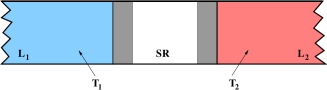
The two-terminal model device is a double barrier system as illustrated in Fig. 1. The leads are invariant along the transport direction and the perpendicular confinement is parabolic, with a level spacing meV. The contacts have distinct temperatures and .
In the framework of multi-channel coherent transport [7, 13, 14], the transmission function is calculated as
| (1) |
where denotes the channel index in lead and . The diagonal matrix is formed by longitudinal wavevectors, , where is the transversal energy for channel and is the total energy. The scattering S-matrix is found in the R-matrix method as . By using the Heaviside functions in Eq. (1) only the open channels are included. The current is calculated as:
| (2) |
where is the Fermi-Dirac distribution function. The open circuit thermoelectric voltage produced by the temperature difference is found by imposing a vanishing current condition, . The value is determined iteratively, by changing step-wise the relative positions of the chemical potentials, which in turn modify the internal electric field between the contacts and the scattering potential as well.
3 Results
We use rectangular barriers of height meV and width nm. The distance between the contacts, including the barriers, is nm. The effective mass of the electron is as for InAs, . We consider , but .
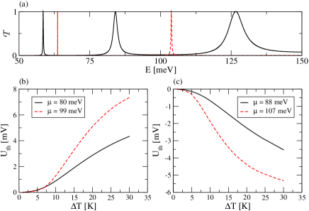
We first examine the influence of the coupling of the resonant system with the contacts by adjusting the widths of the barriers. The transmission functions are depicted in Fig. 2(a), for the system with the specified barrier width , and, for comparison, for . By doubling the barrier width the coupling to the leads weakens and the energy levels are shifted at higher energies while the transmission peaks become narrower. For each system we consider two values for the chemical potential, one placed below and one above the second resonant level . The thermoelectric voltage as a function of temperature difference is presented in Figs. 2(b) and (c). In order to compare the effects produced by the resonance broadening rather than energy shift, the initial chemical potentials of the leads, i. e. at zero bias, denoted by , are chosen symmetrically, on both sides of the transmission maximum of the second resonance peak. The thermoelectric voltage is calculated as , being the chemical potentials of the leads, where is fixed and is adjusted until the current generated by the temperature gradient vanishes.
Two main features are observed. First, the sign of changes as the chemical potential is situated above or under the resonant level. This indicates that the thermoelectric current generated at zero bias has changed sign. Second, the weaker coupling, leading to narrower transmission peaks, corresponds to an enhanced . The behavior can be explained as follows: in the limit of narrow peaks, the condition is fulfilled as the position of the chemical potential in the cold contact, , reaches the resonant level, , and the populations in the two contacts become equal; if the resonance is broader the vanishing current condition is reached sooner as approaches , leading to smaller .
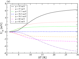
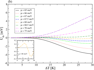
Next, for the system with barrier width of 4.3 nm the zero-bias chemical potential is varied around the first resonance and also between the first two resonances. The two resonances occur at and meV, Fig. 1(a). The results are shown in Figs. 3(a) and (b). In the first case the voltage curves have intersections at finite temperatures. At temperatures below the intersections increases as the chemical potential is set closer to the resonance maximum and at higher temperatures the opposite situation occurs. This is a consequence of the overlap of the Fermi-Dirac distribution functions with the finite width of the resonance. In the second case, one also obtains a sign change for at a fixed temperature, because by changing the chemical potential one out of the two resonances becomes dominant. Moreover, the same effect is also found at a fixed chemical potential and variable temperature, as one can see in the inset of Fig. 3(b).
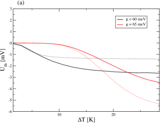
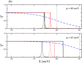
The thermoelectric fields arising between the contacts constitute a source of non-linear behavior and possible enhancement of the thermoelectric effects. Numerical results are shown in Fig. 4(a) to compare the case with and without included in the transmission function given by Eq. 1. The chemical potentials are selected in-between the first two resonances for nm. We find that if the chemical potential is close to the resonance the inclusion of enhances , whereas if is farther away the opposite is true. The situation is illustrated in Fig. 4(b) for two values of the chemical potential. In the presence of the thermoelectric field the resonant levels are shifted in the same direction as the chemical potential . At K, for meV this produces an increase of . However, if we set meV, the population at the resonance is larger and the positions of for the cases with and without become reversed and decreases.
4 Conclusions
The thermoelectric effects which arise in the non-linear temperature
regime in a multi-resonance system were discussed in the framework of
coherent transport, using a scattering formalism based on the R-matrix
method. We point out the typical features of sign changing of the
thermoelectric voltage with respect to varying the chemical potential
around a resonance and in-between two consecutive resonances. In the
latter case, this sign change is also obtained by modifying the temperature
difference at a fixed chemical potential. This effect is shown in the recent
Ref. [15] in the presence of Coulomb
interaction of electrons, whereas we could obtain it without interactions.
Furthermore, we discussed the conditions for enhancing the thermoelectric
effect in the non-linear regime.
Acknowledgement
Support of the EEA Financial Mechanism 2009-2014 staff mobility
grant, the hospitality of Reykjavik University, and instructive discussions with
Sigurdur Ingi Erlingsson are gratefully
acknowledged. G. A. Nemnes also acknowledges support from ANCS under
grant PN-II-ID-PCE-2011-3-0960.
References
- [1] L. D. Hicks, M. S. Dresselhaus, Phys. Rev. B 47, 16631(R) and 12727 (1993).
- [2] T. E. Humphrey, H. Linke, Phys. Rev. Lett. 94, 096601 (2005).
- [3] B. Sothmann, R. Sánchez, A. N. Jordan, M. Büttiker, New J. Phys. 15, 095021 (2013).
- [4] M. F. O’Dwyer, T. E. Humphrey, H. Linke, Nanotechnology 17(11), S338 (2006).
- [5] O. Karlström, H. Linke , G. Karlström, A. Wacker, Phys. Rev. B 84, (2011).
- [6] J. P. Heremans, Acta Phys. Pol. A, 108, 609 (2005).
- [7] G. A. Nemnes, L. Ion, S. Antohe, Physica E 42, 1613 (2010).
- [8] S. F. Svensson et al., New J. Phys. 15, 105011 (2013).
- [9] G. D. Mahan, J. O. Sofo, Appl. Phys. Sci., 93, 7436 (1995).
- [10] Jianming Wang et al., Mod. Phys. Lett. B 20, 215 (2006).
- [11] C. W. J. Beenakker and A. A. M. Staring, Phys. Rev. B 46, 9667 (1992).
- [12] K. Torfason, A. Manolescu, S. I. Erlingson, V. Gudmundsson, Physica E 53, 178 (2013).
- [13] G. A. Nemnes, L. Ion, S. Antohe, J. Appl. Phys. 106, 113714 (2009).
- [14] G. A. Nemnes, A. Manolescu, V. Gudmundsson, J. Phys.: Conf. Ser. 338, 012012 (2012).
- [15] M. A. Sierra and D. Sanchez, Phys. Rev. B, 90, 115313 (2014).