Experimental measurement of the self-healing of the spatially inhomogeneous states of polarization of radially and azimuthally polarized vector Bessel beams
Abstract
We experimentally measured the self-healing of the spatially inhomogeneous states of polarization of radial and azimuthal polarized vector Bessel beams. Radial and azimuthal polarized vector Bessel beams were generated via a digital version of Durnin’s method, using a spatial light modulator in concert with a liquid crystal -plate. As a proof of principle, their intensities and spatially inhomogeneous states of polarization were measured using Stokes polarimetry as they propagated through two disparate obstructions. It was found, similar to their intensities, the spatially inhomogeneous states of polarization of a radial and azimuthal polarized vector Bessel beams self-heal. Similar to scalar Bessel beams, the self-healing of vector Bessel beams can be understood via geometric optics, i.e., the interference of the unobstructed conical rays in the shadow region of the obstruction. The self-healing of vector Bessel beams may have applications in, for example, optical trapping.
pacs:
XXX, XXXA Bessel beam is a light beam that is a solution to the Helmholtz wave equation, existing over a limited region of propagation, and experimentally generated by the interference of conical rays Durnin1 ; Durnin2 . It possesses a property referred to as “self-healing,” i.e., its intensity reappears after propagation through an obstruction. Self-healing can be simply understood via geometric optics Litvin . When a portion of a Bessel beam is obstructed in one plane, the unobstructed conical rays interfere in its shadow region in another plane, as shown in Fig. 1(e). Due to this property, Bessel beams have been extensively studied and have been used for a number of applications; for comprehensive reviews see Review1 ; Review2 ; Review3 ; Dudley1 . For example, when using a Bessel beam for optical trapping, it is possible to simultaneously trap multiple particles in well separated planes Dholakia , and make particle tractor beams Dogariu ; Novitsky1 ; Novitsky2 ; Ruffner .
A vector beam is a light beam possessing a spatially inhomogeneous state of polarization such as radial or azimuthal polarization as shown in Fig. 2(b) and Fig. 2(c), respectively. Vector beams have received significant interest Zhan ; Brown , due in great part to their ability to produce stronger longitudinal field components Brown1 ; Brown2 , and smaller spot sizes Leuchs , as compared to scalar light beams, upon focusing by high numerical aperture objectives. Also, when using vector beams for optical trapping, it is possible to improve the axial and transverse stiffness of the optical trap via radial and azimuthal polarization, respectively Dunlop ; Toussaint ; Sato . Most recently, vector beams have been used for optical communication optica .
Like any other light beam a Bessel beam can have a scalar (spatially homogeneous) or vector (spatially inhomogeneous) state of polarization Bouchal ; Aiello . The great majority of experimental investigations of Bessel beams concern scalar Bessel beams. Yet, a vector Bessel beam possesses the properties of a Bessel beam and a vector beam, as described above, and may be used in comparable applications. For example, it may be possible to improve the axial and transverse stiffness of a tractor beam when using a vector Bessel beam. While there are extensive studies on self-healing of scalar Bessel beams, there are limited studies on self-healing of vector Bessel beams Hasman ; Vyas ; He ; Wu , particularly with respect to their spatially inhomogeneous states of polarization. Previous work only measured the propagation and self-healing of the intensities of vector Bessel beams.
In this work, we experimentally measured the self-healing of the spatially inhomogeneous states of polarization of radial and azimuthal polarized vector Bessel beams. Radial and azimuthal polarized vector Bessel beams were generated via a digital version of Durnin’s method, using a spatial light modulator in concert with a liquid crystal -plate. As a proof of principle, their intensities and spatially inhomogeneous states of polarization were measured using Stokes polarimetry as they propagated through two disparate obstructions. It was found, similar to their intensities, the spatially inhomogeneous states of polarization of a radial and azimuthal polarized vector Bessel beams self-heal. Similar, to scalar Bessel beams, the self-healing of vector Bessel beams can be understood via geometric optics, i.e., the interference of unobstructed conical rays in the shadow region of the obstruction. The self-healing of vector Bessel beams may have applications in, for example, optical trapping.
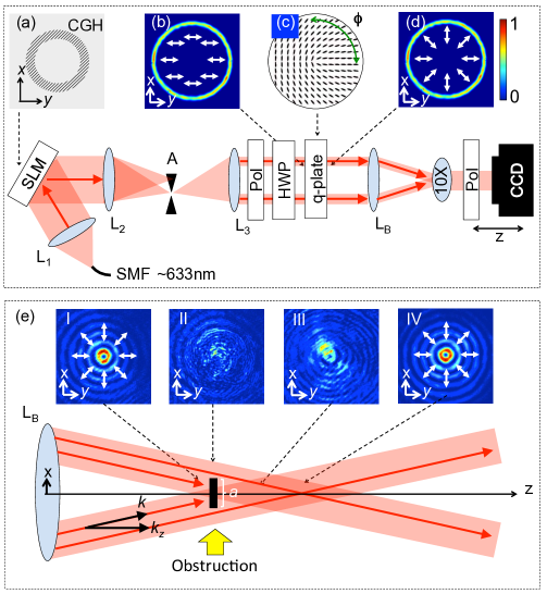
A schematic of the experimental setup is shown in Fig. 1. First, a scalar Bessel beam was generated following Durnin’s method. In Durnin’s method, an annular slit is placed in the back focal plane of a lens and illuminated with a collimated light beam resulting in an annular ring of light. Each point along the annular ring acts as a point source which the lens transforms into a good approximation to a Bessel beam in its focal region Durnin1 ; Durnin2 . A digital method of Durnin’s method was implemented Forbes . An annular slit, additionally superimposed with a linear grating, was created using a computer generated hologram (CGH) displayed on a reflective phase only spatial light modulator (SLM) (HoloEye) as shown in Fig. 1(a). A linear polarized HeNe laser beam ( 633 nm) was spatially filtered by a single mode optical fiber (SMF), expanded, collimated by a lens (), and then illuminated the SLM. The light at the plane of the SLM was then spatially filtered by an aperture (A) in the first diffraction order of a 4f imaging system ( and ), imaged onto the back focal plane of a 10 cm focal length lens (), resulting in the linear polarized annular ring of light shown in Fig. 1(b). A good approximation to a scalar (linearly polarized) Bessel beam was formed in the focal region of lens .

Next, the scalar (linearly polarized) Bessel beam was converted into a vector Bessel beam. There are many methods to generate vector beams including the use of metasurfaces and optical fibers Lin ; Milionea ; Milioneb ; Milionec . Here, we use a -plate Dudley . A -plate is a liquid crystal technology comprising of a thin layer of liquid crystal molecules in-between two thin glass plates. The orientation of the liquid crystal molecules is described by , where is the azimuthal coordinate, and is a half integer. A -plate is schematically shown in Fig. 1(c). Effectively, a -plate is a half wave plate with an azimuthally varying fast axis that can be represented by the Jones matrix marrucci :
| (1) |
Using Jones calculus, it can be easily shown, for a -plate, horizontal (vertical) polarization can be converted into radial (azimuthal) polarization Karimi2 . In general, a -plate converts any state of polarization on the Poincare sphere to a higher-order state of polarization on the higher-order Poincare sphere Milione1 ; Milione2 . The q-plate is also “tunable”; the amount of the incident light’s power converted to radial or azimuthal polarization is directly controlled, i.e., tuned, via a voltage over the -plate. For nm, when the voltage over the q-plate is 5 volts, no light will be converted to radial (azimuthal) polarization, i.e., the light remains linear polarized. When the voltage over the q-plate is 2.3 volts, all of the incident light’s power will be converted to radial (azimuthal) polarization Slussarenko ; Milione4 .
The -plate was placed close to the back focal plane of lens . A linear polarizer (Pol) was placed just before the -plate to ensure the incident light was completely linear polarized. A half wave plate (HWP) was used to rotate the light’s polarization horizontal (vertical). A signal generator generating a 1kHz square wave was used to apply a voltage over the -plate. When the voltage was , a good approximation to a scalar (linearly polarized) Bessel beam was generated in the focal region of lens , as shown in Fig. 2(a). When the voltage was , and the light’s polarization was rotated horizontal (vertical), a good approximation to a radial (azimuthal) polarized vector Bessel beam was generated in the focal region of lens , as shown in Fig. 2(b) (Fig. 2(c)). A 10X microscope objective was used to image each Bessel beam in the focal region of lens onto a CCD camera.
Stokes polarimetry was used to measure the state of polarization of each Bessel beam Goldstein ; Angela . In Stokes polarimetry, the Stokes parameters are measured via intensity measurements and used to calculate the polarization orientation and polarization ellipticity at every spatial point of a light beam. The first three Stokes parameters are given by Goldstein ; Angela :
| (2) | |||||
| (3) | |||||
| (4) |
where , , , and are the intensity of the light beam, at every spatial point, measured after a linear polarizer whose transmission axis is rotated , , , , respectively. are cylindrical coordinates. The total intensity of the light beam is given by and the orientation of the state of polarization is given by Goldstein ; Angela :
| (5) |
A linear polarizer (Pol) was placed just before the CCD camera in the experimental setup described above. The linear polarizer was used to measure , , , and for each Bessel beam as shown in the respective columns of Fig. 2. While the third Stokes parameter, , and therefore the polarization ellipticity, was not measured, as shown in the experimental results, it is qualitatively enough to visualize the self-healing of the spatially inhomogeneous state of polarization of each vector Bessel beam via the polarization orientation.
Finally, each Bessel beam was made to propagate through an obstruction. The results are shown in Fig. 3. The obstruction was created by placing a pitted glass slide possessing multiple, random, speckled, and opaque obstructions in the path of the Bessel beam. The slide’s position was adjusted until an isolated and appropriately sized obstruction was found. The size and position of the obstruction was chosen such that it obstructed approximately a small portion of the Bessel beam near its center. The obstruction is outlined by a dashed white line in Fig. 3. The intensities and states of polarization of each Bessel beam were measured via Stokes polarimetry, as described above, at four propagation distances as they propagated through the obstruction. The four propagation distances are schematically shown in Fig. 1(e): (I) unobstructed (II) obstructed (III) semi-healed (IV) self-healed. is overlaid with such that any change in intensity and orientation of the state of polarization as the Bessel beam propagates through the obstruction can be visualized simultaneously; is encoded by relative contrast, i.e., bright to dark, and is encoded by color.

The self-healing of the intensity and spatially inhomogeneous state of polarization of the scalar (linear polarized) Bessel beam was experimentally measured as it propagated through the obstruction. The results are shown in the first row of Fig. 3(a). As can be seen, as the scalar Bessel beam propagated through the obstruction from (I) to (IV), its intensity self-heals as is expected Review1 ; Review2 ; Review3 ; Dudley1 . Next, the self-healing of the intensities and spatially inhomogeneous states of polarizations of the radialyl and azimuthally polarized vector Bessel beams were experimentally measured as they propagated through the obstruction. The results are shown in the second and third rows of Fig. 3(a), respectively. As the radially and azimuthally polarized vector Bessel beam propagated through the obstruction from (I) to (IV), their intensities self-healed similar to the scalar Bessel beam. As can be seen, similar to their intensities, the spatially inhomogeneous states of polarization of the radially and azimuthally polarized vector Bessel beams also self-healed. This is the salient result of this Letter. There is qualitative agreement between the spatially inhomogeneous states of polarization of the vector Bessel beams when they are unobstructed at (I) and when they self-heal at (IV).
Also, the self-healing of the intensities and spatially inhomogeneous states of polarization of the radially and azimuthally polarized vector Bessel beams were experimentally measured as they propagated through a disparate obstruction. The results are shown in Fig. 3(b). As shown in Fig. 3(b), the size and position of this obstruction was chosen such that it obstructed a larger portion of the vector Bessel beams near their center. The obstruction is outlined by a dashed white line. As can be seen, the intensities and the spatially inhomogeneous states of polarization of the radially and azimuthally polarized vector Bessel beams again self-heal in the presence of the larger obstruction. Similar to the first obstruction, there is qualitative agreement between the spatially inhomogeneous states of polarization of the vector Bessel beams when they are unobstructed at (I) and when they self-heal at (IV).
Similar, to scalar Bessel beams, the self-healing of vector Bessel beams can be understood via geometric optics, i.e., the interference of conical rays in the shadow region of the obstruction, as shown in Fig. 1(e). It is a well-known that the distance in which a Bessel beam is able to reform is given by Litvin :
| (6) |
where is the width of the obstruction and and are the wave-vector and longitudinal wave-vector, respectively. Eq. 6 illustrates that the distance in which a Bessel beam self-heals is dependent on the size and position of the obstruction as well as the opening angle of the cone on which the wave-vectors of the Bessel beam propagate. Here it is assumed that the input field is larger than the obstruction.
There is a relationship between light’s space and polarization degrees of freedom when light is scattered by an obstruction, e.g. Rayleigh or Mie particlesMilione5 . There are comparable relationships in multimode optical fiber Milione6 ; Milione7 . In this respect, a more detailed theoretical analysis of self-healing of the spatially inhomogeneous states of polarization of radially and azimuthally polarized vector Bessel beams, analogous to that of scalar Bessel beams Litvin , is the subject of future work. Nonetheless, as vector Bessel beams possess the properties of Bessel beams and a vector beams, they may have applications in, for example, optical trapping, where self-healing and “vectorness” are both needed, e.g. it may be possible to the improve the axial and transverse stiffness of a tractor beam when using a vector Bessel beam.
In conclusion, we experimentally measured the self-healing of the spatially inhomogeneous states of polarization of radially and azimuthally polarized vector Bessel beams. Radially and azimuthally polarized vector Bessel beams were generated via a digital version of Durnin s method, using an SLM in concert with a liquid crystal -plate. As a proof of principle, their intensities and spatially inhomogeneous states of polarization were measured using Stokes polarimetry as they propagated through two disparate obstructions. It was found, similar to their intensities, the spatially inhomogeneous states of polarization of a radially and azimuthally polarized vector Bessel beams self-heal. Similar, to scalar Bessel beams, the self-healing of vector Bessel beams can be understood via geometric optics, i.e., the interference of conical rays in the shadow region of the obstruction. The self-healing of vector Bessel beams may have applications in, for example, optical trapping.
While there are extensive studies on self-healing of scalar Bessel beamsReview1 ; Review2 ; Review3 ; Dudley1 , there are limited studies on self-healing of vector Bessel beams Hasman ; Vyas ; He ; Wu , particularly with respect to their spatially inhomogeneous states of polarization. Previous work only measured the propagation and self-healing of the intensities of vector Bessel beams. To our knowledge, this is the first experimental measurement of the self-healing of the spatially inhomogeneous states of polarization of radially and azimuthally polarized vector Bessel beams. Future work includes experimentally measuring the self-healing of the spatially inhomogeneous states of polarization of other types of vector Bessel beams such as Full Poincare beams Amber . In contrast to radially and azimuthally polarized light beams, Full Poincare beams experience non-trivial dynamics as they propagate Amber2 ; Milione3 .
Acknowledgments: We thank S. Slussarenko and L. Marrucci for the -plates. GM acknowledges helpful discussions with D. Grier and D. Ruffner, and support from AFOSR Grant. No. No. 47221-00-01, ARO Grant. No. 52759-PH-H, NSF GRFP Grant. No. 40017-00-04, and Corning, Inc. E.K. acknowledges the support of the Canada Excellence Research Chairs (CERC) Program.
References
- (1) “Exact solutions for nondiffracting beams. I. The scalar theory,” J. Durnin, J. Opt. Soc. Am. A , 651 (1987).
- (2) “Diffraction-free beams,” J. Durnin, J. J. Miceli, Jr., and J. H. Eberly, Phys. Rev. Lett. , 1499 (1987).
- (3) “A conical wave approach to calculating Bessel-Gauss beam reconstruction after complex obstacles,” I. A. Litvin, M. G. McLaren, A. Forbes, Opt. Comm. 282, 1078-1082 (2009).
- (4) “Unraveling Bessel beams,” A. Dudley, M. Lavery, M. Padgett, and A. Forbes, Opt. Photon. News 24, 22 29 (2013).
- (5) “Light beats the spread: “non-diffracting” beams,” M. Mazilu, J.D. Stevenson, F. Gunn-Moore, and K. Dholakia, Laser and Photon. Rev. 4, 529 (2010).
- (6) “Bessel beams: diffraction in a new light,” D. Mcgloin and K. Dholakia, Contemp. Phys. 46,15 (2005).
- (7) “Bessel and annular beams for materials processing,” M. Duocastella and C.B. Arnold, Laser Photon. Rev. 6, 607-21 (2012).
- (8) “Simultaneous micromanipulation in multiple planes using a self-reconstructing light beam,” V. Garc s-Ch vez, D. McGloin, H. Melville, W. Sibbett, and K. Dholakia, Nature 419, 145-147 (2002).
- (9) “Negative nonconservative forces: optical tractor beams for arbitrary objects,” S. Sukhov and A. Dogariu, Phys. Rev. Lett. 107, 203602 (2011).
- (10) “Single gradientless light beam drags particles as tractor beams,” A. Novitsky, C.-W. Qiu, and H. Wang, Phys. Rev. Lett. 107, 203601 (2011).
- (11) “Material-Independent and Size-independent tractor beams for dipole objects,” A. Novitsky, C.-W. Qiu, and A. Lavrinenko, Phys Rev. Lett. 109, 023902 (2012).
- (12) “Optical conveyors: a class of active tractor beams,” D. B. Ruffner and D. G. Grier, Phys. Rev. Lett. 1109, 163903 (2012).
- (13) “Cylindrical vector beams: from mathematical concepts to applications,” Q. Zhan, Adv. Opt. Photon. 1, 1-57 (2009).
- (14) “Unconventional Polarization States: Beam Propagation, Focusing and Imaging,” T. G. Brown, (Elsevier, 2011), Vol. 56, pp. 81 129.
- (15) “Focusing of high numerical aperture cylindrical-vector beams,” K. Youngworth and T. Brown, Opt. Express 7, 77-87 (2000).
- (16) “Longitudinal field modes probed by single molecules,” L. Novotny, M. R. Beversluis, K. S. Youngworth, and T. G. Brown Phys. Rev. Lett. 86, 5251 (2001).
- (17) “Sharper focus for a radially polarized light beam,” R. Dorn, S. Quabis, and G. Leuchs Phys. Rev. Lett. 91, 233901 (2003)
- (18) “Forces in optical tweezers with radially and azimuthally polarized trapping beams,” T. Nieminen, N. Heckenberg, and H. Rubinsztein-Dunlop, Opt. Lett. 33, 122-124 (2008).
- (19) “Optical trapping with -phase cylindrical vector beams,” B. J. Roxworthy and K. C. Toussaint Jr, New J. Phys. 12, 073012 (2010).
- (20) “Optical trapping of micrometer-sized dielectric particles by cylindrical vector beams,” Y. Kozawa and S. Sato, Opt. Express 18, 10828-10833 (2010).
- (21) “4 20 Gbit/s mode division multiplexing over free space using vector modes and a -plate mode (de)multiplexer,” G. Milione, M. P. J. Lavery, H. Huang, Y. Ren, G. Xie, T. A Nguyen, E. Karimi, L. Marrucci, D. A. Nolan, R. R. Alfano, A. E. Willner, submitted for publication.
- (22) “Non-diffractive vector Bessel beams,” Z. Bouchal and M. Olivik, J. Mod. Opt. , 1555 (1995).
- (23) “Radially and azimuthally polarized nonparaxial Bessel beams made simple,” M. Ornigotti and A. Aiello, Opt. Express 21, 15530-15537 (2013).
- (24) “Propagation-invariant vectorial Bessel beams obtained by use of quantized Pancharatnam-Berry phase optical elements,” A. Niv, G. Biener, V. Kleiner, and E. Hasman, Opt. Lett. 29, 238-240 (2004).
- (25) “Self-healing of tightly focused scalar and vector Bessel-Gauss beams at the focal plane,” S. Vyas, Y. Kozawa, and S. Sato, J. Opt. Soc. Am. A 28, 837-843 (2011).
- (26) “Propagation properties and self-reconstruction of azimuthally polarized non-diffracting beams,” M. He, Z. Chen, S. Sun, and J. Pu, Opt. Comm., 294(1) 36-42 (2013).
- (27) “Generation and self-healing of a radially polarized Bessel-Gauss beam,” G. Wu, F. Wang, and Y. Cai, Phys Rev. A 89, 043807 (2014).
- (28) “Generating superpositions of higher order Bessel beams,” R. Vasilyeu, A. Dudley, N. Khilo, and A. Forbes, Opt. Express 17 23389 (2009)
- (29) “Nanostructured holograms for broadband manipulation of vector beams,” J. Lin, P. Genevet, M. A. Kats, N. Antoniou, and F. Capasso, Nano Lett.13(9), 4269 4274 (2013).
- (30) “Cylindrical vector beam generation from spun fiber,” H. I. Sztul, D. A. Nolan, G. Milione, X. Chen, J. Koh, and R. R. Alfano,Proc. SPIE 7227, 722704 (2009).
- (31) “Cylindrical vector beam generation from a multi elliptical core optical fiber,” G. Milione, H. I. Sztul, D. A. Nolan, J. Kim, M. Etienne, J. McCarthy, J. Wang, and R. R. Alfano, Proc. SPIE 7950, 79500K (2011).
- (32) “Cylindrical vector beam generation from a multi elliptical core optical fiber,” G. Milione, H. Sztul, D. Nolan, J. Kim, M. Etienne, J. McCarthy, J. Wang, and R. Alfano, in CLEO:2011 - Laser Applications to Photonic Applications, OSA Technical Digest (CD) (Optical Society of America, 2011), paper CTuB2.
- (33) “Generating and measuring nondiffracting vector Bessel beams,” A. Dudley, Y. Li, T. Mhlanga, M. Escuti, and A. Forbes, Opt. Lett. 38, 3429 (2013).
- (34) “Optical spin-to-orbital angular momentum conversion in inhomogeneous anisotropic media,” L. Marrucci, C. Manzo, and D. Paparo, Phys. Rev. Lett. 96 163905 (2006).
- (35) “Polarization pattern of vector vortex beams generated by -plates with different topological charges,” F. Cardano, E. Karimi, S. Slussarenko, L. Marrucci, C. de Lisio, and E. Santamato, Appl. Opt. 51, C1 (2012).
- (36) “Higher-order Poincar sphere, Stokes parameters, and the angular momentum of light,” G. Milione, H. I. Sztul, D. A. Nolan, and R. R. Alfano, Phys. Rev. Lett. , 053601 (2011).
- (37) “Higher order Pancharatnam-Berry phase and the angular momentum of light,” G. Milione, H. I. Sztul, D. A. Nolan, and R. R. Alfano, Phys. Rev. Lett. , 190401 (2012).
- (38) “Tunable liquid crystal -plates with arbitrary topological charge,” S. Slussarenko, A. Murauski, T. Du, V. Chigrinov, L. Marrucci, and E. Santamato, Opt. Express 19, 4085 (2011).
- (39) “Tunable supercontinuum light vector vortex beam generator using a -plate,” Y. Rumala, G. Milione, T. Nguyen, S. Pratavieira, Z. Hossain, D. Nolan, S. Slussarenko, E. Karimi, L. Marrucci, and R. Alfano, Opt. Lett. , 5083 (2013).
- (40) D. Goldstein, Polarized Light (CRC 2003).
- (41) “All-digital wavefront sensing for structured light beams,” A. Dudley, G. Milione, R. R. Alfano, A. Forbes, Opt. Express 22(11), 14031-14040 (2014).
- (42) “Optical memory effect from polarized Laguerre Gaussian light beam in light-scattering turbid media,” P. Shumyatsky, G. Milione, R. R. Alfano, Opt. Comm. 321, 116-123 (2014).
- (43) “Spin-orbit-interaction-induced generation of optical vortices in multihelicoidal fibers,” C. N. Alexeyev, A. N. Alexeyev, B. P. Lapin, G. Milione, M. A. Yavorsky, Phys. Rev. A 88(6), 063814 (2013).
- (44) “Determining principal modes in a multimode optical fiber using the mode dependent signal delay method,” G. Milione, D. A. Nolan, and R. R. Alfano, to be published in J. Opt. Soc. Am. B.
- (45) “Full Poincare beams,” A. Beckley, T. Brown, and M. Alonso, Opt. Express 18, 10777-10785 (2010).
- (46) “Diffraction Free Stokes Distributions in a Full Poincare Beam,” A. Beckley, M. Alonso, and T. Brown, in Frontiers in Optics 2010/Laser Science XXVI, OSA Technical Digest (CD) (Optical Society of America, 2010), paper FThN2.
- (47) “Manifestation of the Gouy phase in vector-vortex beams,” G. M. Philip, V. Kumar, G. Milione, and N. K. Viswanathan, Opt. Lett. , 2667 (2012).